11. Applications and Implications
For my final project I would like to make a DPV. A DPV, or dive scooter, is basically just a battery and an electric motor in a waterproof hull with a propeller behind it. The purpose of it is to tow a scuba diver behind it to increase the spatial range during the limited time underwater due to temperature, limited amount of breathing gas and intake of gases under pressure that only gradually leave the human body again on the way to the surface.
Last year I was using a DPV that is based on a commercial product from the company Suex. Several years ago someone seperated the battery compartment from the motor compartment, sealed both compartments with turned plastic partes and connected them with wires. The motor control was replaced by a magnetic switch outside of the hull and a relais in the battery compartment. Instead of different speeds the scooter was just able to be turned on and off. The only way of getting a feedback from the battery is realising that it ran flat when the motor shuts off. Someone used it to propell a scubster with two of those. That’s why the battery compartment was seperated from the rest. The motors were placed outside of the scubster’s hull and the batteries inside. Over the years the whole assembly was leaking, the connections and cables were failing and it stopped working.
Thats why I rewired it and connected the battery compartment to the rest again last year. The most important thing I learned by doing this is how hard it is to make something seriouslly waterproof. I assume that’s the reason why commercial DPVs are that costly and are mostly sold for several thousand Euros. That makes them unaffordable for most recreational scuba divers.
My motivation
There are already a lot of diving scooters on the market. All the features I want to include in my design have already been in one of the products on the market in one way or the other. So, why should I make one myself instead of just buying an commercial off-the-shelf solution?
The commercially available scooters that are affordable aren’t particularely high quality and the scooters that actually work well aren’t affordable. Therefore, I want to make a DPV that fulfills my requirements and needs but still is affordable. And it is , at least in my eyes, an awesome opportunity to combine my Fab Acedemy’s masterpiece with something that I’m going to use a lot and which is not only collecting dust in a shelf.
My idea
The idea is to start with something straightforward. I’d like to make an assembly in a hull that contains two switches, a propeller, a motor, batteries, a PCB, and three LEDs. In the first step I just want the propeller to spin when I push a button while everything is assebmled in and around the hull, so that it can be handled safely.
In the next iteration I want to include the second switch and the PCB to enable different speeds. When pushing that switch, I want to rotate between four different speeds where the propeller is spinning at 25, 50, 75, and 100 % of its maximum rpm.
The third iteration should lead to an indication of the battery status. The three LEDs, visivle from outside the hull, are going to be used for that. All three LEDs turned on indicate a battery charge between 100 and 75 %. two LEDs indicate a battery charge between 75 and 50 %, one LED a battery charge between 50 and 25 % and all LEDs turned off lead to the conclusion that the battery charge fell below 25 %.
Components
Commercially produced components
I decided not to make every single part myself. Buying some components should enable me to stay within the timeframe of this course but still come up with an afforable solution. I neither have access to the machines needed to make those parts nor do I have the necessary knowlage. Making those components would even be more expensive than buying them. Therefore, I’m going to purchase the following parts.
Batteries
The voltage I’m going to operate the DPV with is 24 V. The power density and power to weight ratio in lithium polymer batteries are way higher than in lead acid batteries. The batteries mainly determine the weight, and therefore, also the volume of the scooter. It’s supposed to be neutrally buoyant. That means that a higher weight leads to a higher volume to displace more water, and therefore, lead to more buoyancy. The smaller the hull is the smaller the drag will be. The overall surface area determines the skin drag, whereas the profile has an influence on the form drag. A nearly ideal fineness ratio of about 6 would be ideal. That means that the hull is six times longer than its maximum width.
Considering this, a relatively narrow lithium polymer battery or 18650 cells that I can arrange according to my needs would be a good solution. On the other hand ther is still a chance that I’m going to flood the whole system. Somehow my gut feeling tells me to rather flood a lead acid battery than to flood a lithium polymer battery. Both solutions can be found in commercial scooters. In the end my financial resources were the deciding factor towards three lead acid batteries that are going to be connected in series. The advantage of this is, that I can use those three batteries in series, hence 36 V, to power the motor and just draw power from one battery though a voltage regulator to power my microcontroller.
I decided for four of these 12 V 18 Ah lead acid batteries that can be ordered on that website. The total costs are 143.60 €. The plan is to respectively connect two in parallel and then those two arrangements in series. 24 V and 36 Ah of capacity should keep me moving for a bit.
Motor
Motors used in those scooters usually draw 200 W upwards and run at a maximum of 3000 to 4000 rpm. A gear reduction leads to way lower rpm at the screw. My initial plan was to go with a brushless motor like this for about 60 € from ebay. But my latest online research has shown that rpm and power aren’t as important as I thought. I need torque! A lot of torque! That means that I will probably need to continue my search for a motor that fits my requirements. At the moment I’m thinking about keeping the motor mount variable, so that I can lateron switch to a bigger motor if needed and for now test a brushless motor like the one from ebay that is available for free.
Motor controller
To control the brushless motor I need a motor controller like this one for roughly 110 €. As soon as the motor has been spicified, I can also choose the motor controller.
Waterproof bearing
The whole purpose of a DPV is to somehow transfer the torque from the motor inside the hull to the screw to propell the scuba diver through the water. Since most electric motors dont like water too much, the trick is to transfer the torque through the hull without allowing water to come in. A possible solution is a radial shaft seal around the shaft to seal the breach through the hull. Products that are sealing at up to 10 bar are available for less than 4 €.
Waterproof switches
To give input signals to the pcb to rotate between the different speeds and turn the motor on and off, I’m planning to use reed switches for 80 Cents a piece. They can be placed inside the hull and are operated from the outside with a magnet to avoid breaches through the hull.
Torque limiter
The worst case possible would be to cut off fingers by reaching into the spinning propeller. To avoid that, the power transmission from the motorto the propeller should be interrupted somewhere along the shaft as soon as the torque reaches a certain threshold. The requirement is to interrupt the transmission of torque when limbs or other objects end up in the screw. This can be achieved with a torque limiter for 25 €.
Latch clamps
The two parts of the hull need to be held together, so that the O-ring in the sealing surface is compressed. My choice of assuring this are latch clamps.
O-ring
The two parts of the hull held together by latch clamps are going to be sealed with an O-ring. It’s not going to sit on the face of the connecting surfaces but rather radially between a sleeve and the part that sits in that sleeve. The costs for that O-ring is going to be an hand full of Euros.
Selfmade components
3D printing
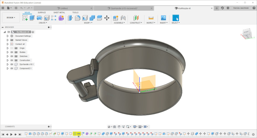
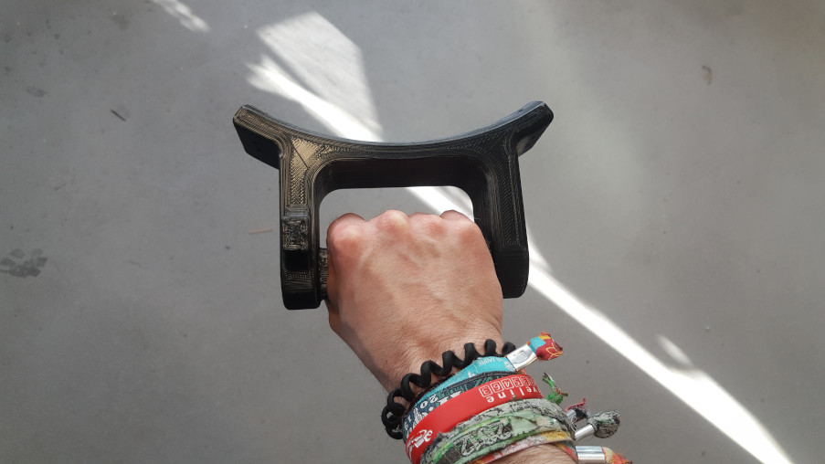
Parts I’m going to 3D print are the handle and cort nozzle and the propeller.
I am going to use 100 % infill to avoid cavities inside those parts, even though it’s not necessary regarding the parts’ strength. It’s not easy to end up with waterproof 3D printed party that are still waterproof at greater depths, hence greater pressures. The goal is to end up with a scooter with buoyancy characteristics that don’t change with variable depth. That means that cavities that slowly fill with water or are compressible are extremely annoying while using the scooter. Since the density of the PLA being used to print is about 1.24 g/cm³, ergo not too far away from the density of water, the weightwise trade-off is not too bad.
Most probaly I’m also going to use the technique of 3D printing to make some mounts for the motor, the motor controller, the pcb and the batteries inside the hull. Since those parts are inside the hull, and therefore, (hopefully) not in contact with water at all.
Of course, this also involves the CAD design of those parts.
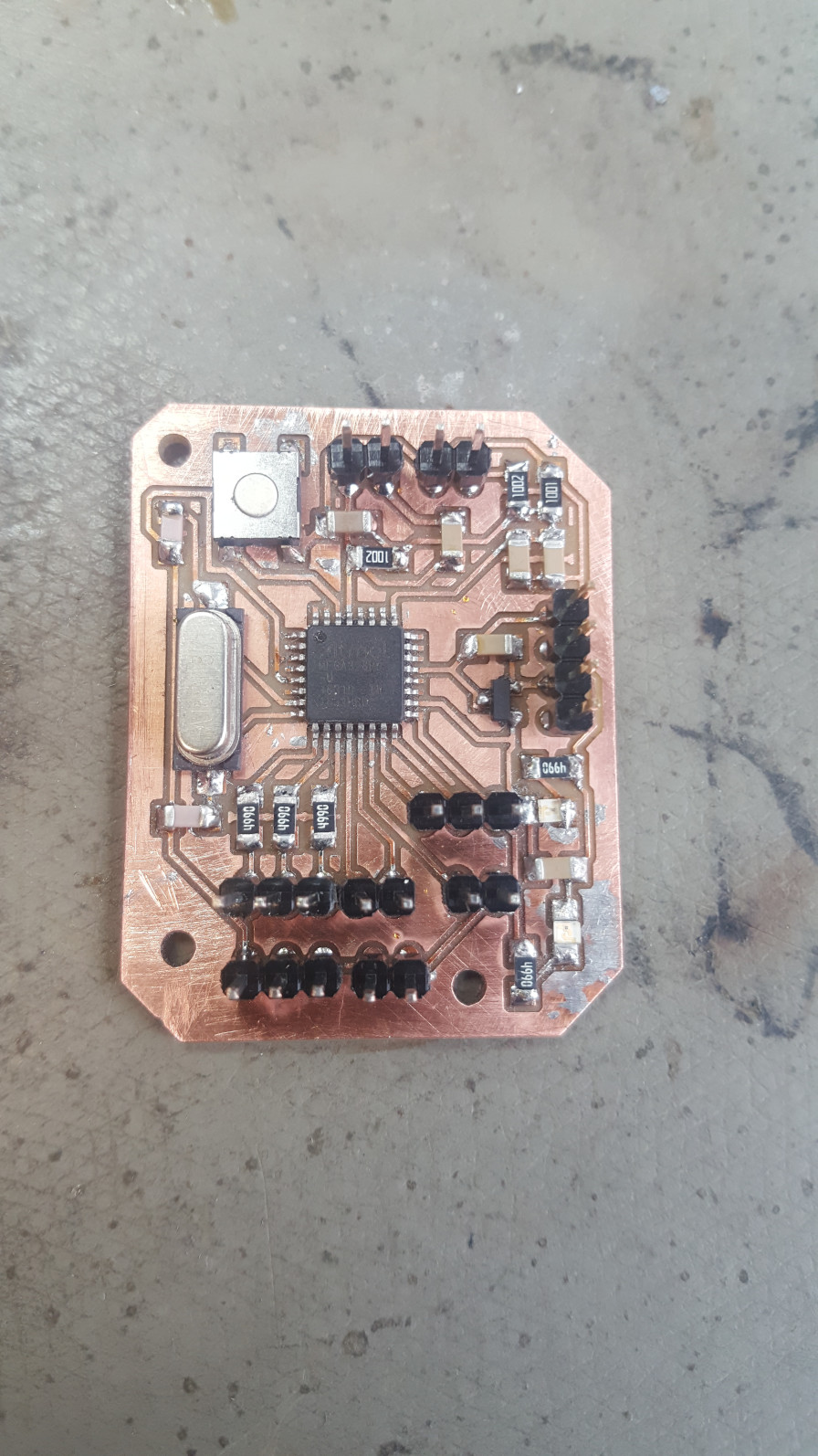
Electronics design and production
For my electronics design assignment I already made a board that is meant to be used in the scooter. I equipped it with all the necessary pins to connect a motor controller, three LEDs and two switches. It also has a voltage regulator to connect to one 12 V battery to power the board and a voltage divider to break down the voltage of two serial 12 V battery blocks to a fraction of that total voltagethat the board an handle. This allows it to measure that fraction of the total voltage and calculate the battery status.
CNC milling
The cort nozzle somehow needs to be connected to the hull to keep its position relative to the propeller as stable as possible. The connecting members serving this purpose are also used as anker points for the line that pulls the scuba diver through the water on his harness. I would like to mill those S-shaped parts out of POM, a relatively stiff plastic.
Moulding and casting
The hull of the scooter needs to be a body that is pressure stable up to around 6 bar. It also needs a cavity inside to contain the electronics components. I am planning to use moulding and casting to make the hull in two parts out of a fiberglass composit.
Open questions
The next thing to find out is which motor to take. I need to do some further research to exactly specify the requirements to make an educated choice. The choice of the motor controller then depends on this. Once I determined all the components and made or ordered them, I need to weigh them to get an idea of the overall weight. That then tells me the needed overall volume to achieve neutral buoyancy in fresh water. For salt water I then just add some weight to it. Knowing the overall volume I can then design the geometry of the hull.
Evaluation
I don’t want to follow a pass or fail evaluation for the product I’m making as my final project. Since I’m going through several iterations in design and programming, I want to evaluate the scooter according to how many milestones I reach.
Ending up with an enclosed system that includes at least two different speeds and a battery status indicator is the basic expectation. Likewise a waterproofness at a depth of one meter and the ability to tow me at all. A nice to have feature is then the ability to rotate through several speeds and indicate the speed that I just switched to by flashing the LEDs for two seconds.
One of the most interesting questions is to which depth the system is going to be waterproof, hence fully funtionable. The only way to find that out exactly is to reach the point where the system fails. Somehow I don’t feel like reaching that point. Testing it in 10 m steps down to 30 m is a benchmark I could live with. I would then know that it still works at 30 m but wouldn’t know at which depth the system will fail.