3. Computer Aided design
Preparations
For me this week started with reorganising some of the first week’s content. I also recieved a new computer from my employer, the Rhine Waal University of Applied Sciences. Therefore, I had to reinstall some software and rechange some settings like making hidden files visible and showing filename extensions.
I also prepared git bash again to upload my repository to the fabcloud again. I added my username and my email address with
git config --global user.name “YOUR_USERNAME”
git config -–global user.email “jSmith@mail.com”.
I then generated a SSH key using the command
ssh-keygen -t rsa -C "$your_email"
and copied it with
clip < ~/.ssh/id_rsa.pub.
Finally, I added the key to the gitlab.fabcloud as well.
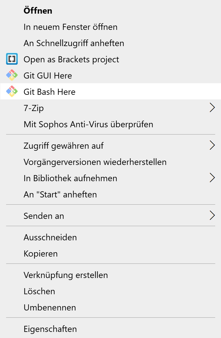
I now was ready to upload the changes I made to my git repository by opening my week02 folder in the explorer and rightclicking on it. By clicking on “Git Bash Here” I opened Git Bash and was already in the right directory.
To upload the changes I (as before) used the commands
git add .
git commit -m "commit message"
git push.
Time to start designing the final project idea!
2D design
For making the 2D sketch of the dpv’s design I used Inkscape. I downloaded the software from here and installed it. To make the software usable, I had to increase the icon size in the settings due to the extremely high resolution to size ratio of my computer’s display. A 4k resolution on a 15.6” screen lead to extremely small icons in that programm.
To create a shape I used the ‘Create rectangles and squares’ function on the program’s left panel. I then created a rectangle. The ‘Edit paths by nodes’ function allowed me to make the rectangle’s edges round. The ‘Create Bezier curves’ button enables the mode to create splines. With those funktions I made the following first sketch of the dpv.
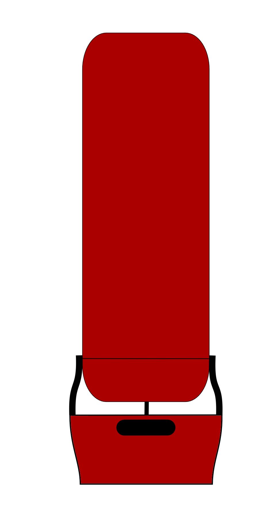
Changes in width and stroke style of different lines made them look different in different layers. With the layers I can decide which part is in front of others.
3D design
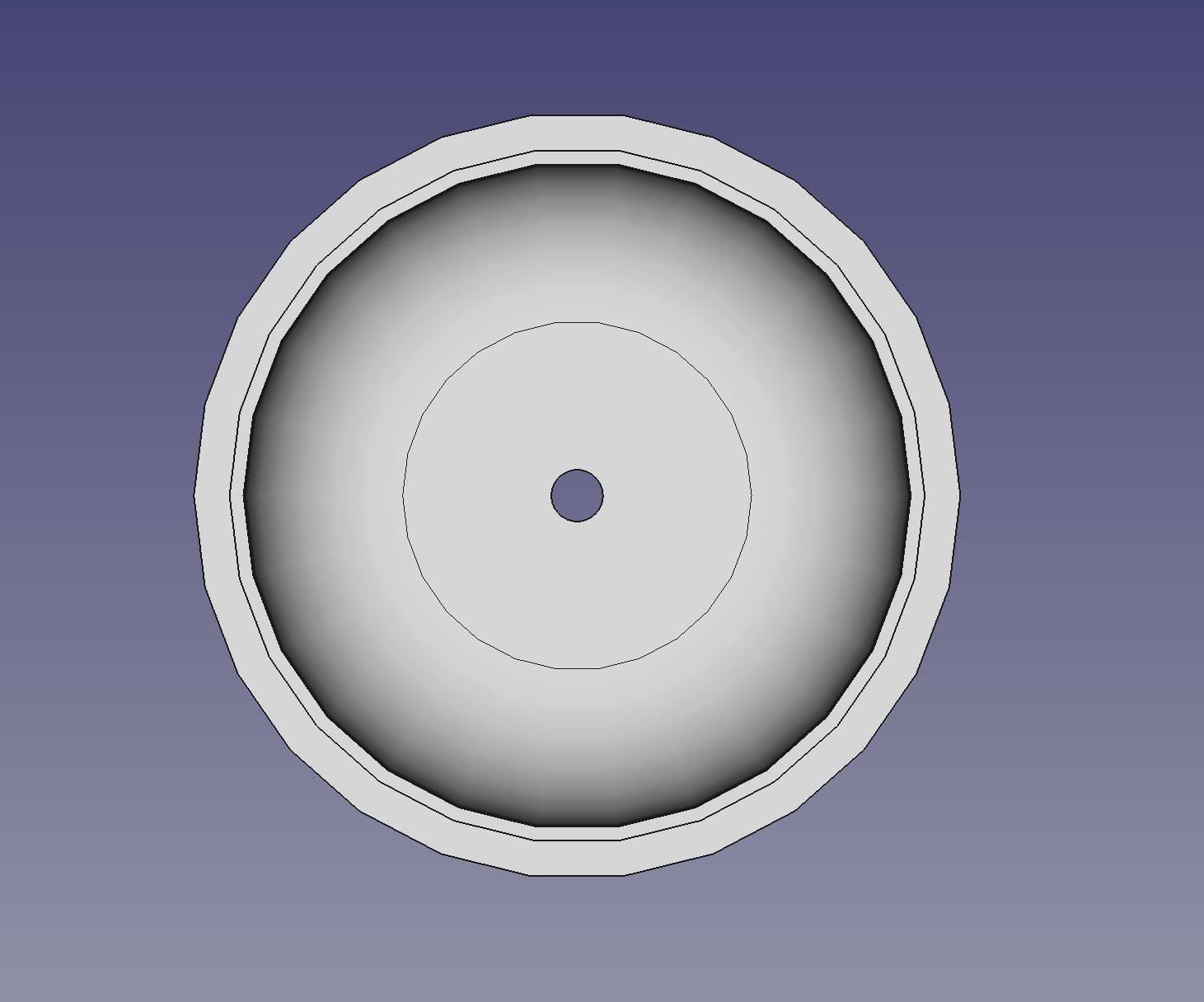
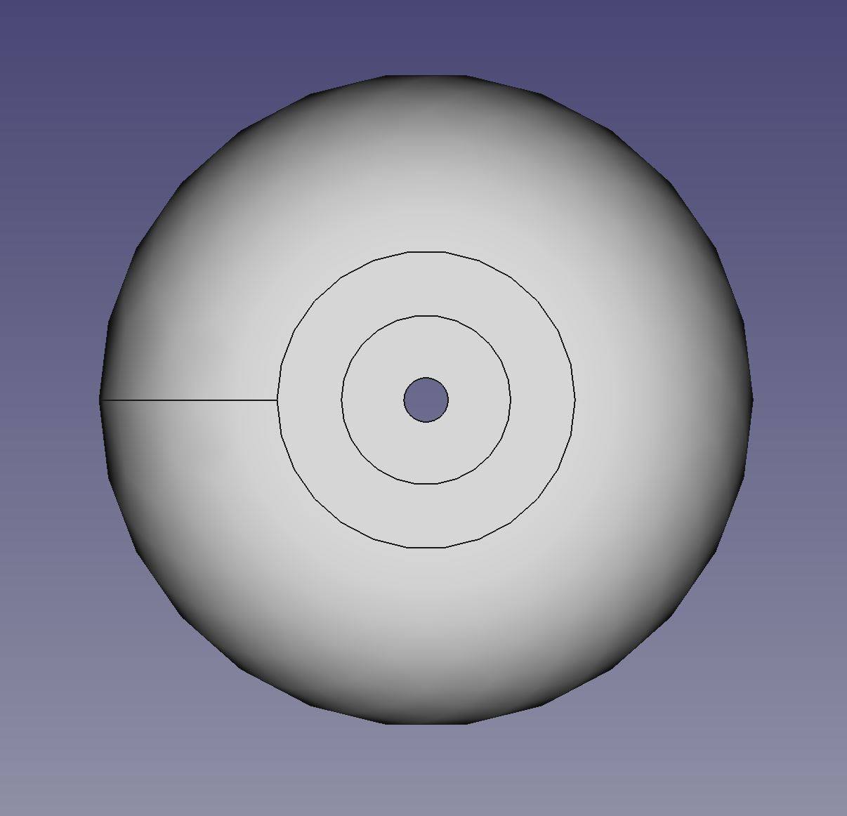
I used FreeCAD to model the dpv’s body in 3D. FreeCAD has different workbenches to do different jobs. The part design workbench is what I used for modelling the body. I started with a sketch where I drew in one quadrant. With a polyline I designed one half of the cut through the radially symmetric part. The arc function allowed me to make the round edges.
I closed the sketch and revolved it around the y axis.
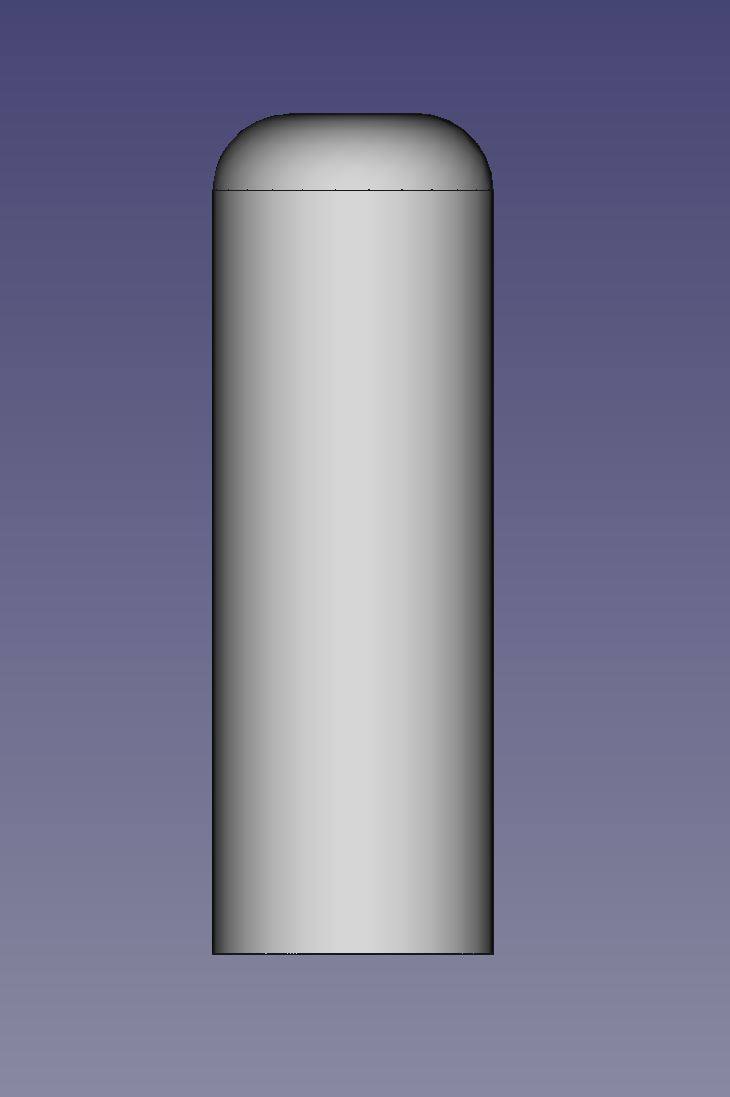
Then I created a sketch on the top and the bottom surfaces, drew a circle and created a pocket with the selected sketches.
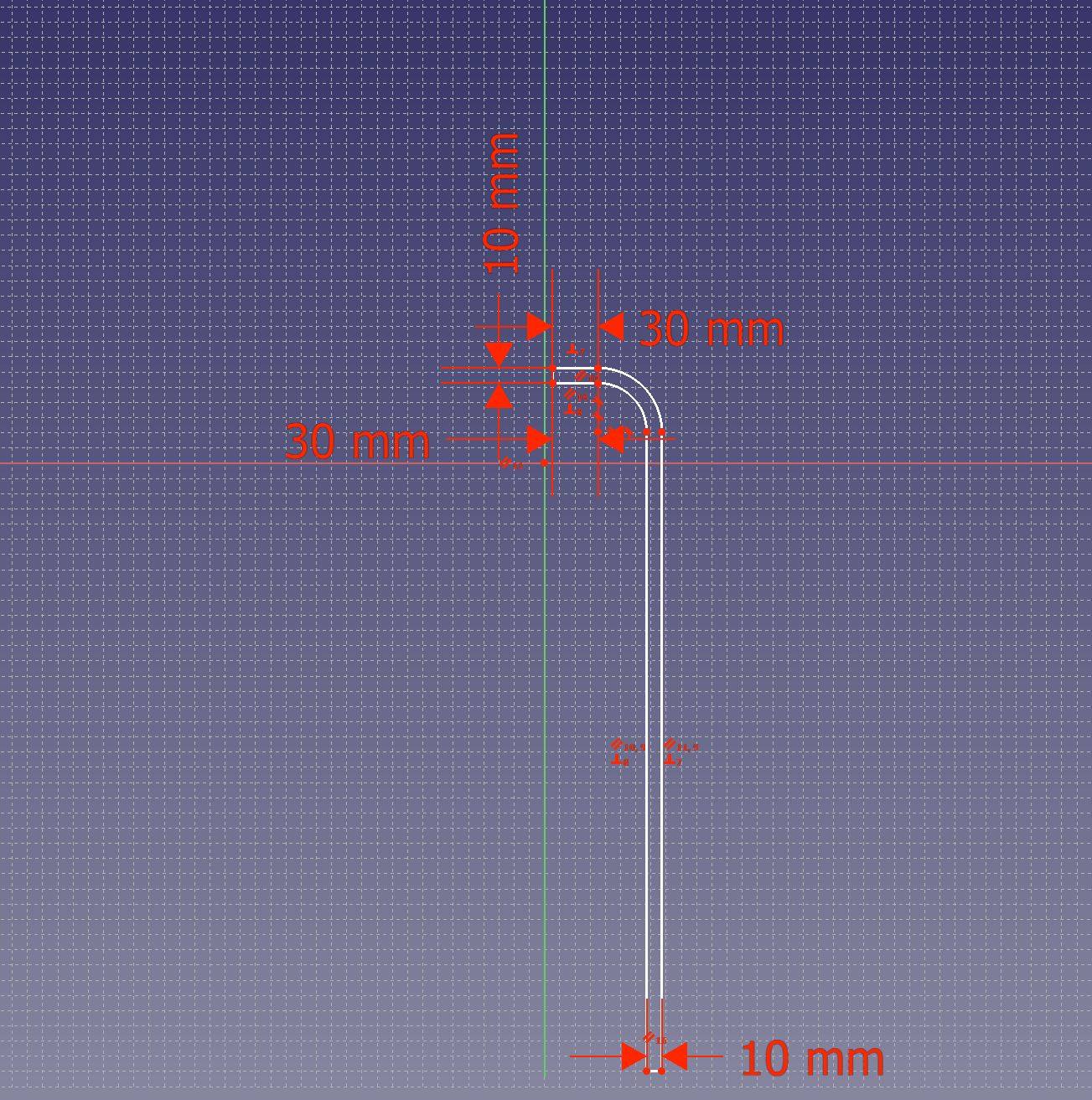
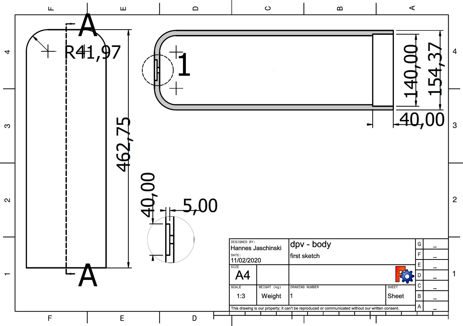
I then switched to the TechDraw workbench to make a technical drawing of the part.