10. Input devices
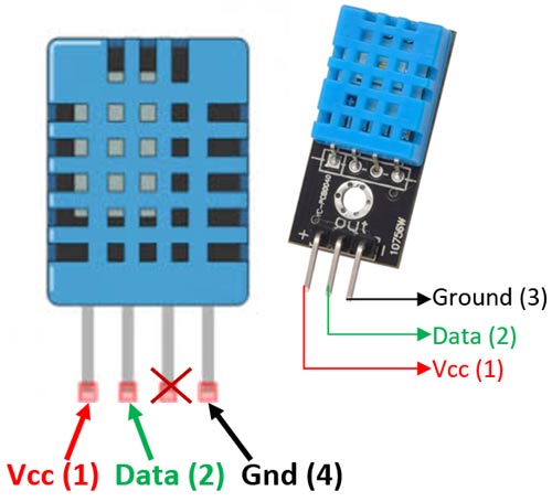
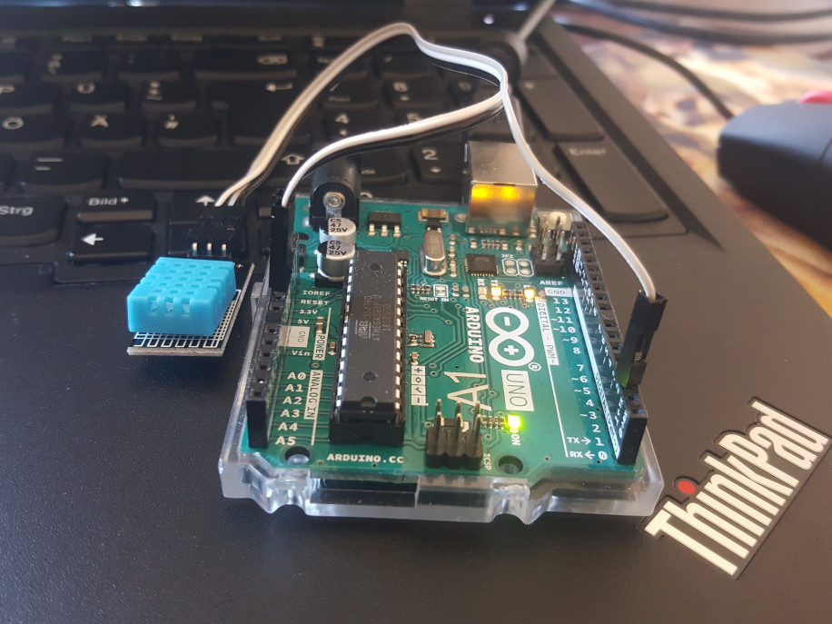
This weeks assignment is all about using some kind of sensor to measure something with the help of a PCB. I went through the parts I had and picked a DHT11 to measure the humidity and temperature of the air at my home. Due to the unavailability of ressources and machines, I didn’t make a board especially for this purpose but used an Arduino Uno instead. According to the schematic, I connected the left pin of the sensor to the VCC of the Arduino, the right pin to GND and the middle pin to pin 2 on the Arduino. The Arduino was connected to my computer via USB.
Writing the code
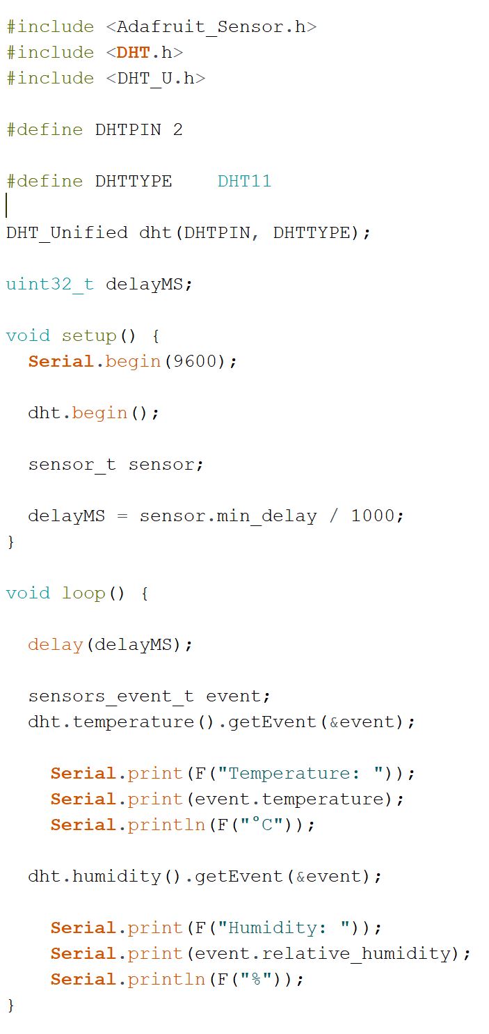
For working with the code, I used the Arduino IDE. I started with the DHT_Unified_Sensor file from the DHT sensor library in the software’s examples to get the sensor working. I uncommented the right sensor (DHT11) and changed the pin to pin 2. To make the code compile withour an error message, I installed the Adafruit dht library.In the Arduino IDE menue I set the board to Arduino Uno und the port to COM14. By clicking on upload, I uploaded and started the programm on the Arduino UNO. I opened the serial monitor to see the results of the sensors measurements.
Understanding the code
Using a code that someone else wrote can be a cheap way of getting something to work. My aspiraation goes beyond that. I wanted to understand it. Therefore, I went through the comments in the code and removed everything that I thought is not needed for just measuring and indicating the plain humidity and temperature. I ended up with the following: