14. Networking and communications
Group Assignment
As usual, amazing electronics documentation done by Carla Molins.
Individual Assignment
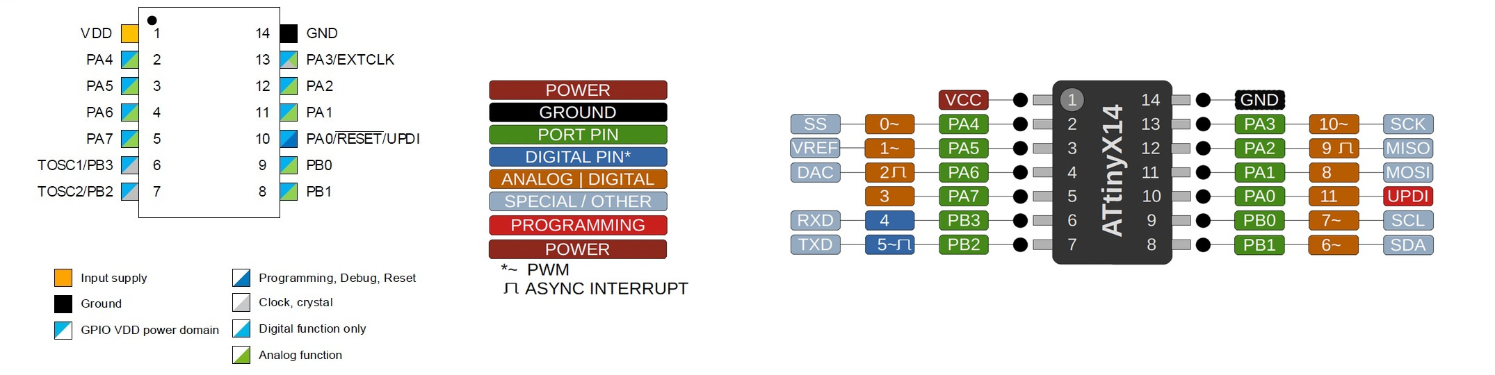
I am going to test the I2C connection to communicate 2 boards with Attiny1614.
This page explains quite well how to tackle the topic when you don’t know anything about it like me!
Paola del Castello’s documentation was also used in the following to understand better. Looks like experience designers have similar ways of thinking!
What is I2C?
I2C (Inter-Integrated Circuit Bus), also commonly known as TWI (Two Wire Interface), is a two-wire synchronous serial bus cable.
SDA stands for serial data.
SCL stands for serial clock.
Each line has a pull-up resistance between the line and the positive rail. A good pull-up resistor is from 1k to 10k Ohms.
I2C allows to have a synchronous communication.
This means the data transfer is synchronized through a clock signal.
Serial: Serial transferred data means that a single bit is transferred at a time over a single cable.
Bus: A bus is a system that allows many devices to communicate with each other through a single set of cables. They use an addressing system, in which each device has a unique address.
The I2C operation modes.
In general, there are 4 distinct modes of operation:
1.a master transmits - controls the clock and sends data to the followers.
2.a master receives - controls the clock and receives data from the follower.
3.a follower transmits - the device does not control the clock and sends data to the master.
4.a follower receives - the device does not control the clock and receives data from the master.
The Master device is simply the device that controls the bus at a given time; this device controls the clock signal and generates the START and STOP signals.
How does the communication take place?
”
1.Sending of the START bit (S) by the master.
2.Sending of the follower address (ADDR)7 by the master.
3.Sending of the Read (R) or Write (W) bit, which are worth 1 and 0 respectively (always by the master).
4. Waiting for/sending of the Acknowledge bit (ACK).
5.Sending/receiving the data byte (DATA).
6.Waiting for/sending the Acknowledge bit (ACK).
7.Sending the STOP bit (P) by the master.
Steps 5 and 6 can be repeated to read or write more bytes.
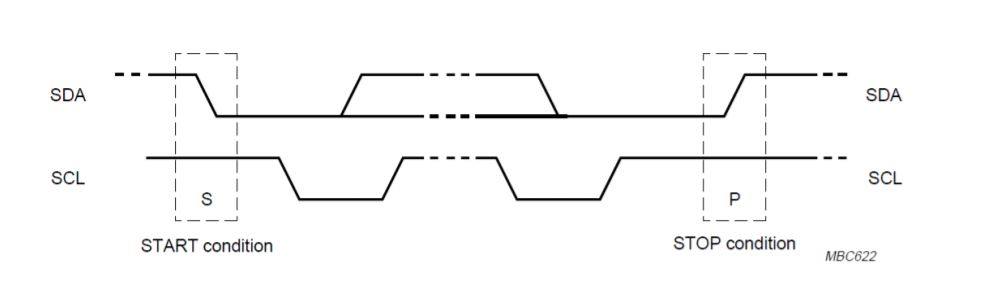
So, a communication takes place within two signal sequences that the master will send on the I²C bus, these are the START and STOP command. The basic rule is that in data transmission, the SDA signal can only change state while the SCL signal is low, and its value is then read during the rising or falling edge of the SCL signal becoming high. If the SDA signal changes value while SCL is high, it means that the master is not transmitting or receiving data, but is starting or ending communication, through the start and stop commands.
“
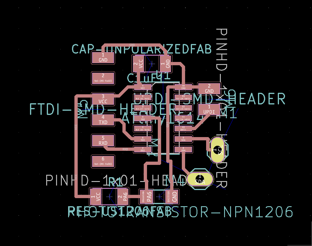
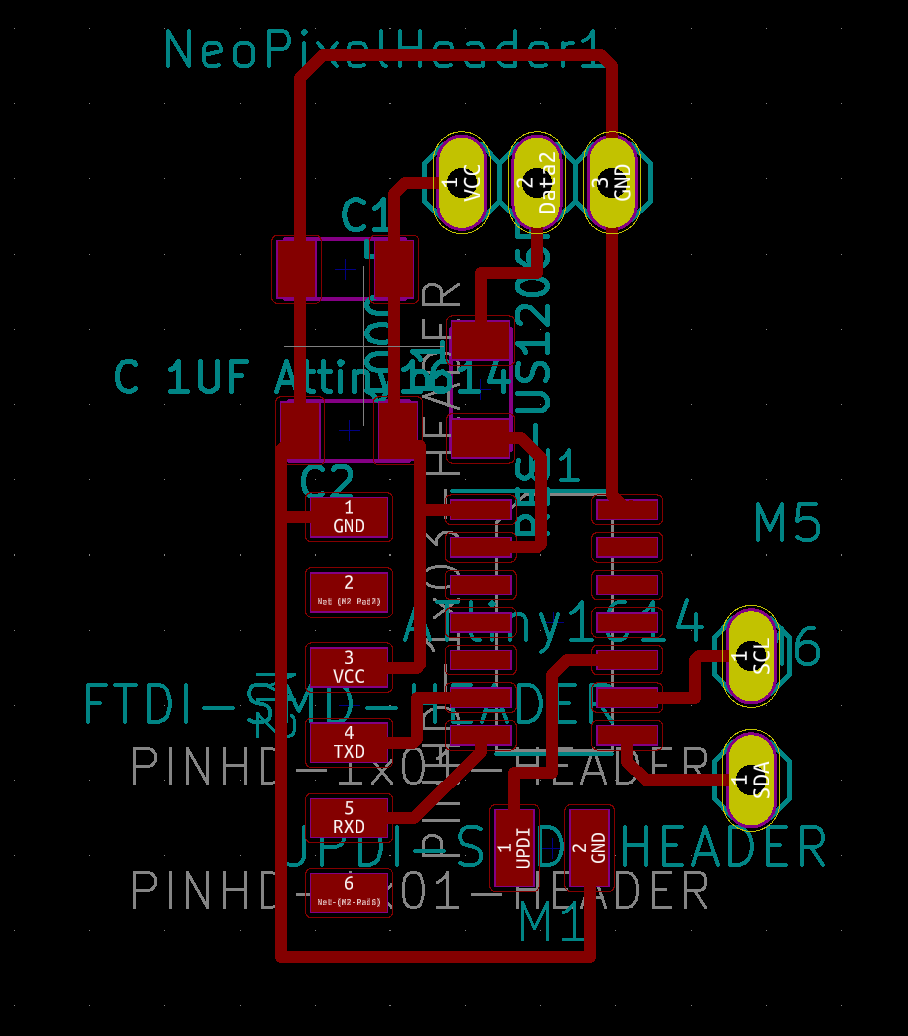
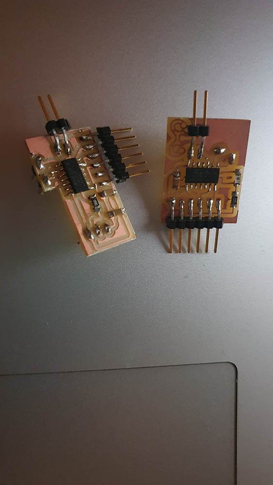
Boards
These are the two boards that I designed to communicate between each other.
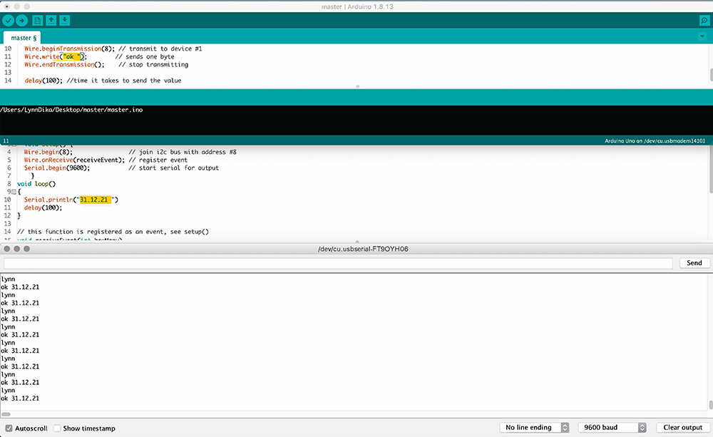
Code
The follower code

#include <Wire.h>

  void setup() {
  Wire.begin(8);                // join i2c bus with address #8
  Wire.onReceive(receiveEvent); // register event
  Serial.begin(9600);           // start serial for output
    }
void loop()
{
  Serial.println("31.12.21 ");
  delay(100);
}

// this function is registered as an event, see setup()
void receiveEvent(int howMany)
{
  Serial.println("lynn ");

    char c = Wire.read(); // receive byte as a character
    Serial.print(c);         // print the character

}
The master code

#include <Wire.h>

void setup()
{
  Wire.begin(); // join i2c bus
}

void loop()
{
  Wire.beginTransmission(8); // transmit to device #1
  Wire.write("ok ");        // sends one byte
  Wire.endTransmission();    // stop transmitting

  delay(100); //time it takes to send the value
}