3.Electronics Design & Production
Electronic Design
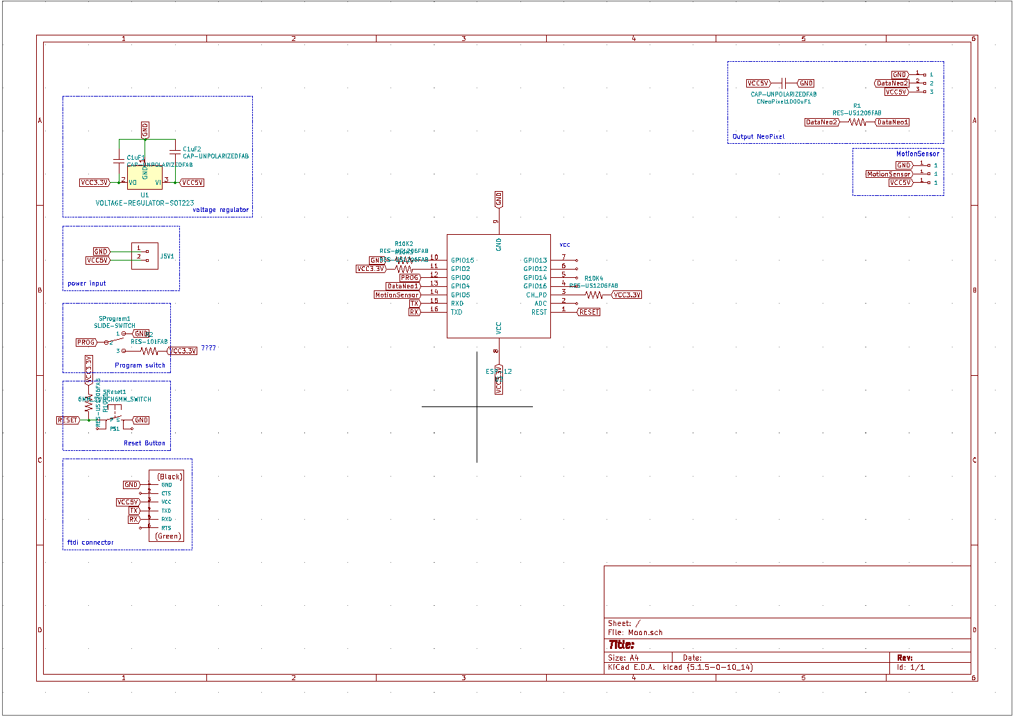
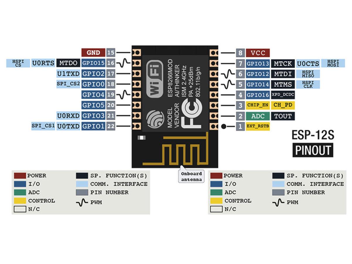
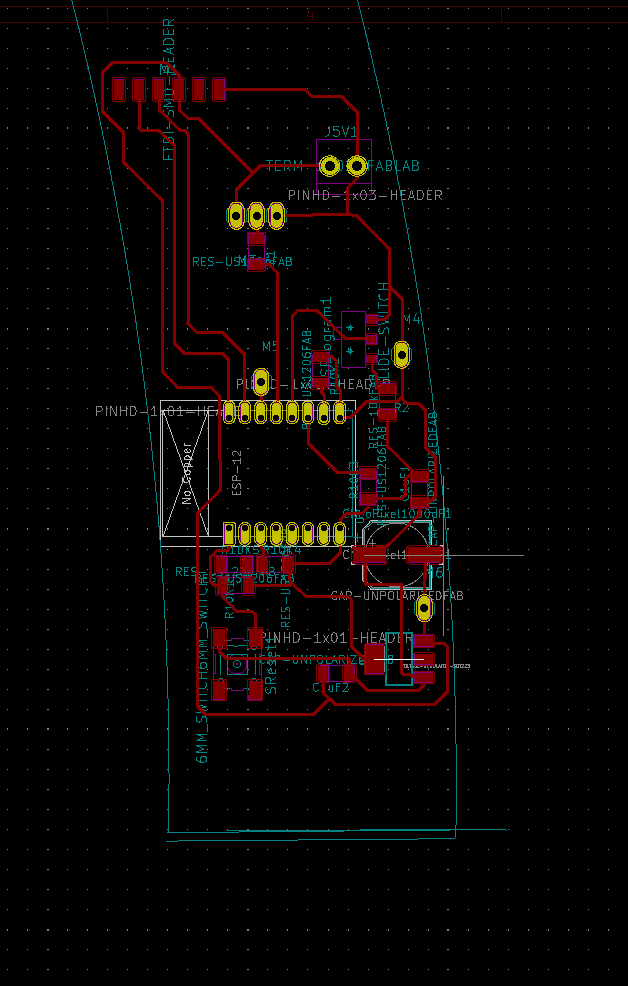
My board will be powered by an ESP8266 12S, which can connect to WiFi. The ESP 8266 is alimented at 3.3V while a USB connection and FTDI aliment at 5V, so I had to take that into consideration. Add to that that the output are neopixels, which are alimented at 5V. It took me so long to find the adequate footprint for Kicad but it ended up working.
The board will be integrated within the circular form, therefore the outer cut was adapted to the diameter of the lamp case.
The Bill of Material for the PCB:
- ESP8266 - ESP12
- Voltage Regular with 2 1uF capacitors to power the ESP8266 at 3.3 V
- Slide Switch to program the ESP12.
- A reset switch connected to the REST switch.
- an FTDI connector
- a power input for 5V and GND
- a transmission signal processing control chip RCWL-9196
- a Neopixel strip with a 1000uF capacitor connected to the 5V.
The sensor module I used is a RCWL-0516 microwave radar sensor module Human body induction switch module Intelligent sensor.
Features: 1, transmission signal processing control chip RCWL-9196 2, wide operating voltage range: 4.0-28.0V 3, compared with the traditional infrared feeling PIR, with the penetrating detection capability. 4, block time, distance adjustable.
It connects to 3V3, which is perfect. Since it is adaptable, I can tweak it when I decide to refine the design.