11. Input devices
Group Assignment
For the group assignment we measured the electrical consumption of our setup.
What are sensors?
Sensors allow us to capture signals from the world around us and translate them into values that could be read on our computer!
Carla’s expansive study of sensors really helped me understand how each work and I will use it as a reference as we go.
Some of the sensors that caught my eye and I would like to experiment with are:
- GY-521 MODULE - MPU 6050 SENSOR
- BIG & SMALL SOUND MODULE
- PIR sensor
Explaining Pulse Width Modulation
Pulse Width Modulation allows us to regulate
the average voltage getting into our components.
More voltage = more speed.
Earlier in history, the approach was to dissipate the energy by using resistors.
We can think of Pulse Width Modulation as a constant switch going on and off causing the current to modulate, creating an average.
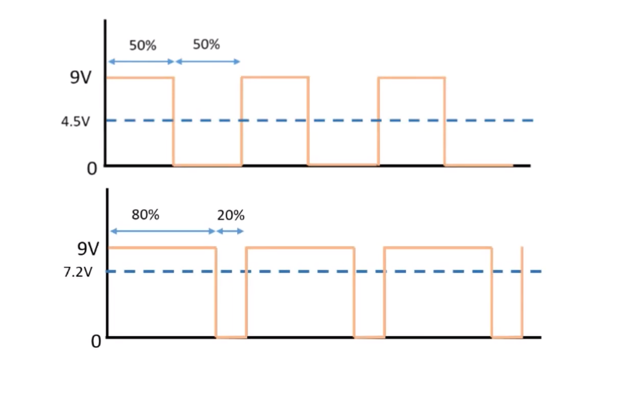
Duty cycle is the ON time.
This video explains it very well.
Analogic Vs Digital Sensors
I will expand with time on this section as it interests me. But this link really helps.
In brief, this is how we can talk about the difference and how it would affect in the moment of choosing between one or the other.
Analog signals & outputs
- continuously variable or changing.
- Give a range of values running through time, with various amplitudes and frequency.
- Are more prone to external noise and error in the output signal.
- Usually have bigger ranges
Digital signals& outputs
- Digital signals are binary.
- They are generated by voltage,
0 OFFand1 ON. They havedefined levels. - Are more precise and directly read by any micro-controller
Board Design
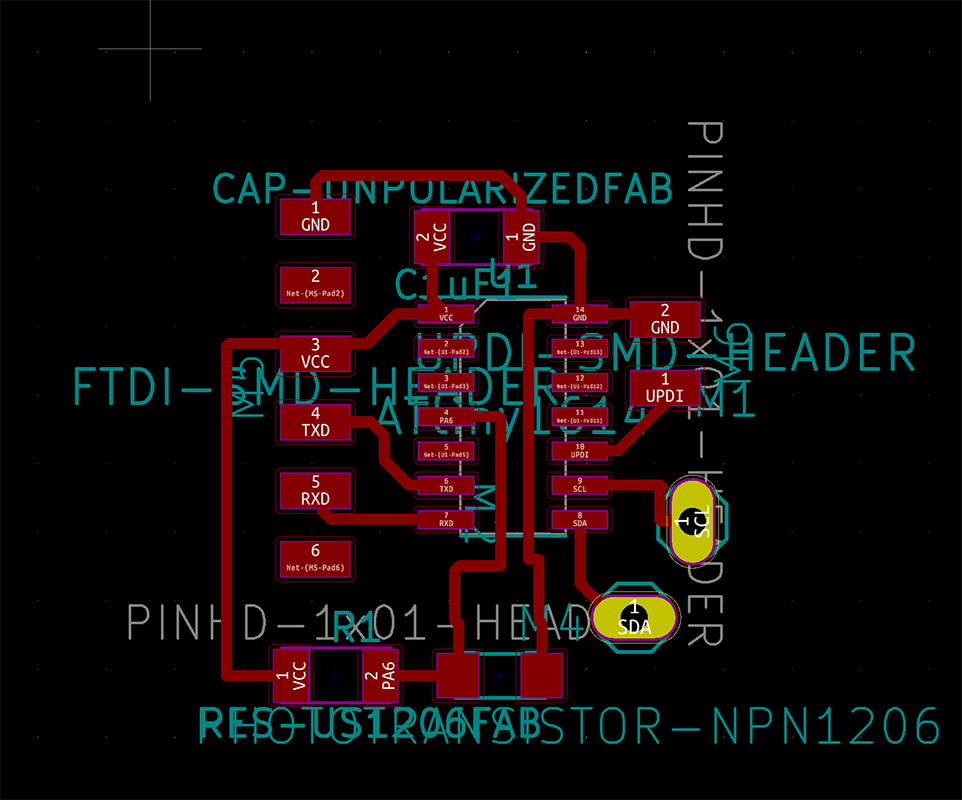
My main sensor for this week is a phototransistor. More especifically, this one
I chose this one because of its spectral sensitivity that allows to read wavelength visible to the human eye; which goes between 600 nm and 900 nm.
In order to protect the phototransistor, I use a 10 MegaOhm resistor.
I produce the circuit with two different structures; changing the order of the phototransistor and the resistor
to see what might be the change in the values.
The connection that worked better was connecting the resistor to the voltage source.
In this case, the value received were higher, which allowed bigger range of measurement as seen here.
It ranges from 0 all the way up to 381.
When it is the phototransistor connected to the voltage source, it seems that the
electric current is too weakened and the value read ranges from 0 to 13.
Arduino Code
I push the code using the FTDI into my AtTiny1614:
void setup() {
  // initialize serial communication at 9600 bits per second:
  Serial.begin(9600);
}

// the loop routine runs over and over again forever:
void loop() {
  // read the input on analog pin 2:
  int sensorValue = analogRead (2);
  // print out the value you read:
  Serial.println(sensorValue);
  delay(1000);        // delay in between reads for stability
}
Downloadable Files.
These are the final files
Learnings
This is so much fun. My colleagues have done an amazing job documenting. I would really like to focus on that more.