12. Output devices
For this week, I am testing out the NeoPixels by creating my own Attiny1614 board with an input of capacitive sensor and an output of the NeoPixels.
Group Assignment
documented it very well!
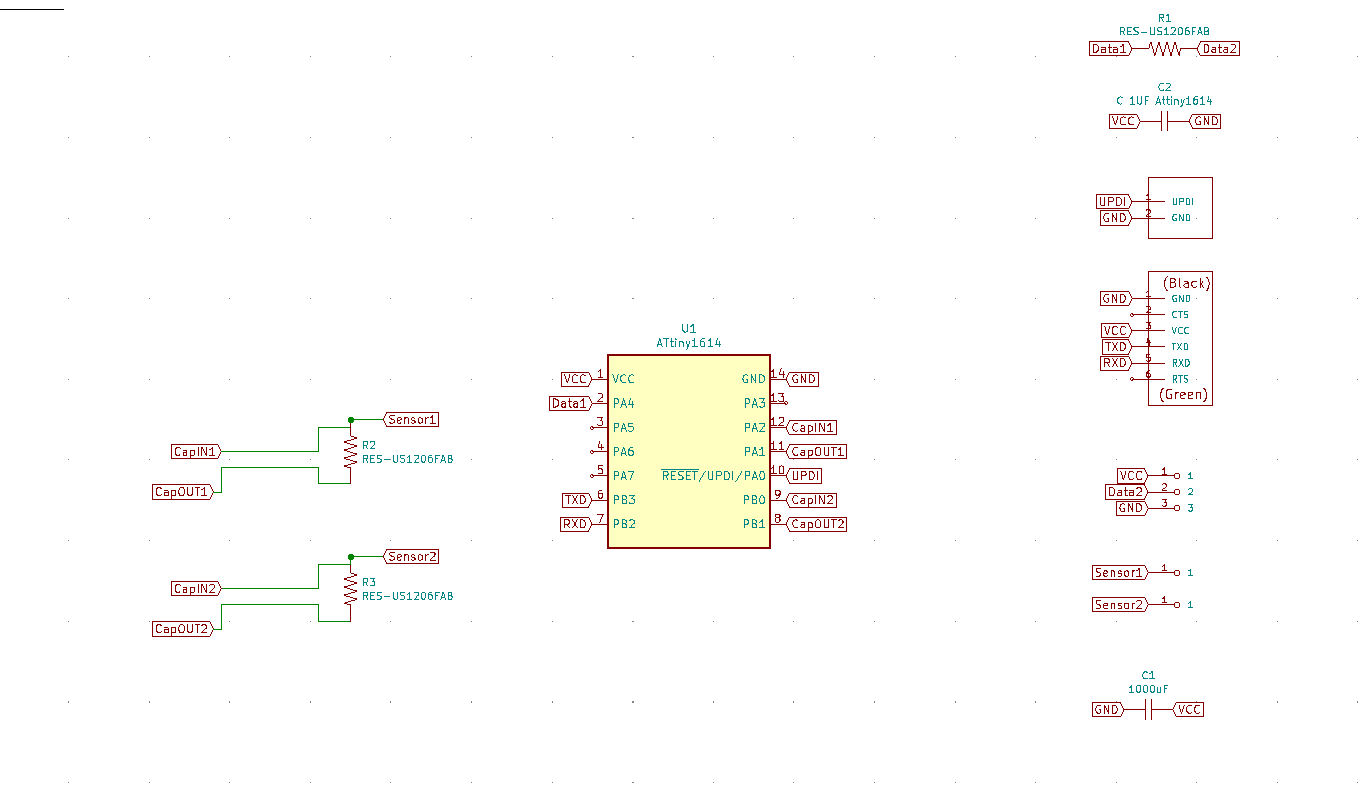
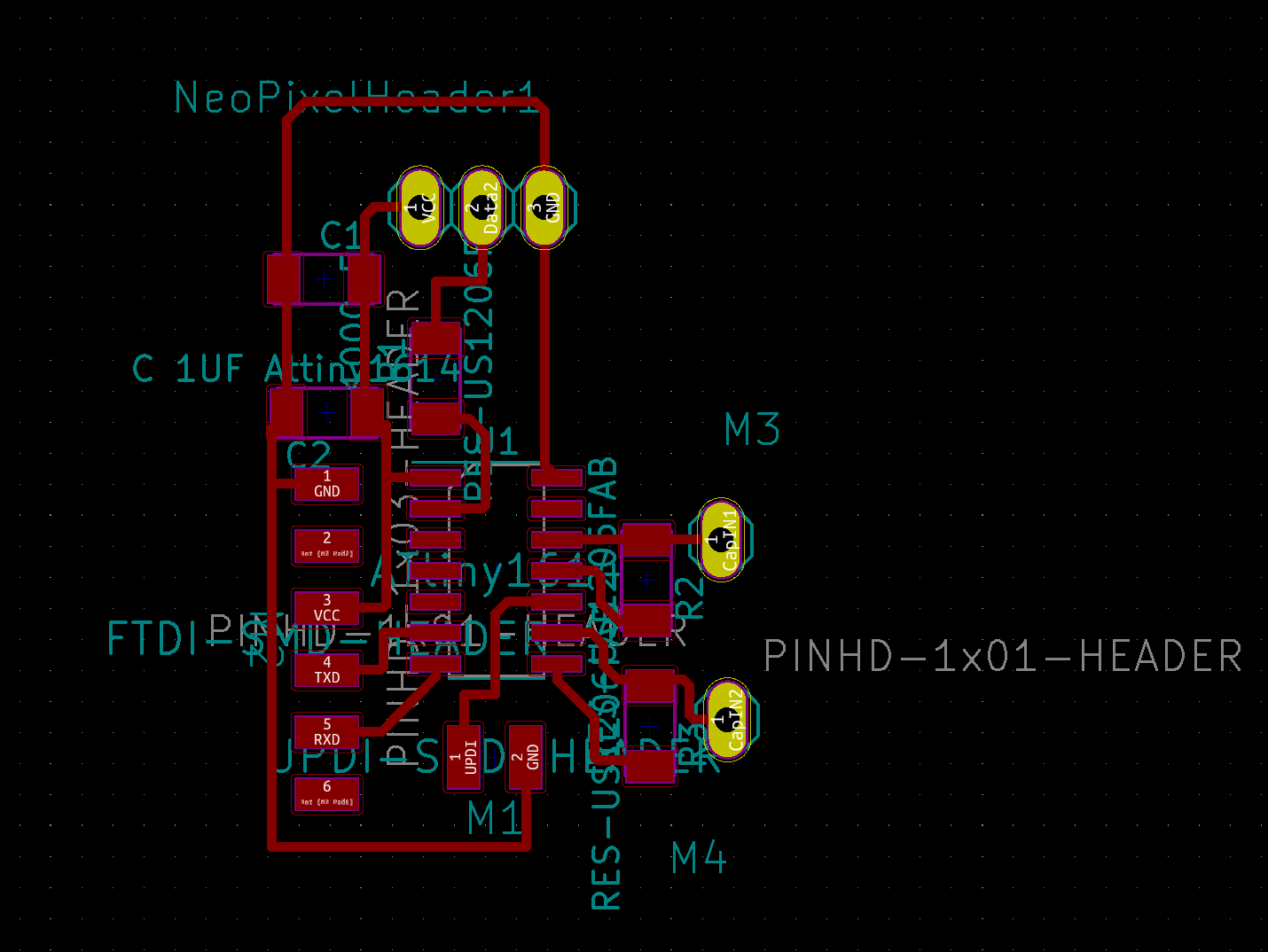
The board design
In order to design my board, I know that I need an FTDI to power & communicate with the computer, a UPDI to program the AtTiny 1614 and a 1uF capacitor to decouple and avoid any noise or catastrophe when communicating with the micro-controller.
A neoPixel led strip has three different pins: GND , VCC & Code.
It is recommended to have a resistor and a capacitor connected to the NeoPixel to avoid any burning.
I use a 499 Ohm Resistor and a 1uF capacitor.
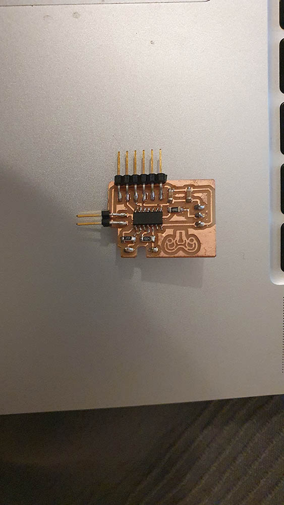
Being very honest, I feel pretty good about creating PCB boards. Usually my milling is on point & my soldering is okey.
Thi is the final result.
Capacitive sensor
I decide to have two pins out for the capacitative sensors in order to test with different materials and capacities. The resistor is of 1 MOhm.
For my input, which is a capacitive sensor, the logic is quite simple.
Two pins are connected together by a resistor. One is set as an input, the other as an output.
When the output is HIGH, and if the input is reading HIGH, it means the current is arriving to input without having any other outlet.
When the output is HIGH, and if the input is reading LOW, it means the current has another outlet, and is being capacitated at the other end by the conductive material and the touch.
I test this code on an Arduino in order to understand how it works and i seem to get the logic!
#include <CapacitiveSensor.h>

/*
 * CapitiveSense Library Demo Sketch
 * Paul Badger 2008
 * Uses a high value resistor e.g. 10M between send pin and receive pin
 * Resistor effects sensitivity, experiment with values, 50K - 50M. Larger resistor values yield larger sensor values.
 * Receive pin is the sensor pin - try different amounts of foil/metal on this pin
 */


CapacitiveSensor   cs_4_2 = CapacitiveSensor(7,6);        // 10M resistor between pins 4 & 2, pin 2 is sensor pin, add a wire and or foil if desired


void setup()
{
   cs_4_2.set_CS_AutocaL_Millis(0xFFFFFFFF);     // turn off autocalibrate on channel 1 - just as an example
   Serial.begin(9600);
}

void loop()
{
    long start = millis();
    long total1 =  cs_4_2.capacitiveSensor(30);

    Serial.print(millis() - start);        // check on performance in milliseconds
    Serial.print("\t");                    // tab character for debug windown spacing

    Serial.print(total1);                  // print sensor output 1
    Serial.print("\t");

    delay(1000);                             // arbitrary delay to limit data to serial port
}
For some reason, on my board, it is not working. I will be checking with my instructor about this.
Trouble with versions of the board manager
A couple of days before I start working with my attiny1614, some update has been pushed to the boards manager, which started bugging and interfering with my capacity to compily code for the attiny1614.
In order to solve that, I had to go to the repository and read through which versions of Arduino IDE and the board manager to keep.
Eventually, and ironaically, what helped is removing the link of an esp8366 from the boards manager.
Neo Pixels Libraries.
The NeoPixel code is only compatible for compiling on an Attiny1614 with tinyNeoPixel.
This doc goes through the main code to be used while coding for tinyNeoPixel library.
I am still picking up the habit of going through readme files, but from this one, I can see the following:
- 10 MHz & 20 MHz clocks are now supported.
- This library only supports one wire LEDs, not double-wire ones.
- The Library has two versions - the
tinyNeoPixel_Staticsaves greatly on memory. it is recommended to use it.
Technically, this is a library identical to the adafruit one but that is compatible with Attiny. From this document, I can see that the code to be used is identical to the AdaFruit one.
My final Output Code
In the following few weeks, I will go deep on coding the NeoPixels as it is part of my final project. Meanwhile; this is the basic code I edited in order to code my NeoPixels.
// NeoPixel Ring simple sketch (c) 2013 Shae Erisson
// Released under the GPLv3 license to match the rest of the
// Adafruit NeoPixel library

#include <tinyNeoPixel.h> // neither FastLed.h nor AdaFruit.h work with Attiny

// Which pin on the Arduino is connected to the NeoPixels?
#define PIN        0 // it is connected to pin 0 of Attiny1614

// How many NeoPixels are attached to the Arduino?
#define NUMPIXELS 8 // Popular NeoPixel ring size

// When setting up the NeoPixel library, we tell it how many pixels,
// and which pin to use to send signals. Note that for older NeoPixel
// strips you might need to change the third parameter -- see the
// strandtest example for more information on possible values.
tinyNeoPixel pixels(NUMPIXELS, PIN, NEO_GRB + NEO_KHZ800);

#define DELAYVAL 500 // Time (in milliseconds) to pause between pixels

void setup() {
  pixels.begin(); // INITIALIZE NeoPixel strip object (REQUIRED)
}

void loop() {
  pixels.clear(); // Set all pixel colors to 'off'
  // The first NeoPixel in a strand is #0, second is 1, all the way up
  // to the count of pixels minus one.
  for(int i=0; i<NUMPIXELS; i++) { // For each pixel...

    // pixels.Color() takes RGB values, from 0,0,0 up to 255,255,255
    // Here we're using a moderately bright green color:
    pixels.setPixelColor(i, pixels.Color(0, 150, 0));
    pixels.show();   // Send the updated pixel colors to the hardware.
    delay(DELAYVAL); // Pause before next pass through loop
  }
}
And this is the outcome:
Downloadable files
Kicad for AttinyBoard
Code for Arduino
Nice links
NeoPixel Effect generator
FadeCandy easy NeoPixelControl Board
Learnings
-
I need to dedicate a good portion of my time in order to understand how to especifically deal with brightness, and LED control.
-
Documentation’s importance is being revealed to me day after day. I cannot imagine remembering all this code, debugging & libraries if it isn’t for the documentation of the open-source community.
-
Honestly, Lynn, you need to double-check your soldering, because sometimes you spend hours trying to make sense of a communication error that is solved by making sure one pin of your micro-controller is well-soldered.