08. Embedded Programming
Individual Assignment: read a microcontroller data sheet + program your board to do something, with as many different programming languages and programming environments as possible.
Group Assignment
The documentation that we did as a group was beautifully documented by the only & only Adrien
Reading my datasheet
I am going to learn how to start programming my pomodoro with an 
In order to do this, I need to understand a little bit better my chip. This sparkfun helped me understand better how read a datasheet.
These are the main chapters we can find the datasheet.
The overview
It literally showing you the main information that will allow to choose with chip works for what you need.
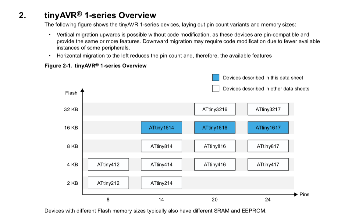 One of the first things we can see in the overview is the
 the flash memory* & the number of pins.
my chip, as it name indicates has a flash memory of 16kb and 14 pins.
-
The flash memoryis the memory that doesn’t need current and is non-volatile. This new youtube channel seem to be promising in explaining electronics for beginners in a thorough manner. -
Memories
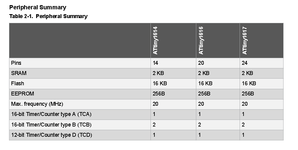
The peripheral summary displays the main information of my microchip.
Besides that I got earlier about the glash memory and the pin number, i discover that my chip has:
- 2 KB SRAM, which is the data my CPU and GPU need to access quickly for smooth operations.
It’s a type of storage that is very fast, yet it is volatile.
When disconnected from electricity, data dissipates.
SRAM stands for Static Random Access Memory.
DRAM stands for Dynamics Random Access Memory.
Let’s think about this way, a gaming PC needs a 16gb of RAM, because you are in constant need of processing volatile instataneous data. Very far from the capacity of my micro-processor that has a 2KB RAM.
RAM memory is usually used for data and instructions.
- A 256 bit ROM memory(https://www.youtube.com/watch?v=Y0h_yZGXDxA) ROM memory is read-only memory. it is non-volatile memory.
The memory of this chip is EEPROM, which means that it’s read-only memory is electrically erasable. It is also programmable.
ROM memory is usually used for booting and core functions.
-
a 16 kb flash memory is the memory used to write the code & flash my microcontroller. It is flashed into the ROM memory. (i guess - it will get clearer with time.)
-
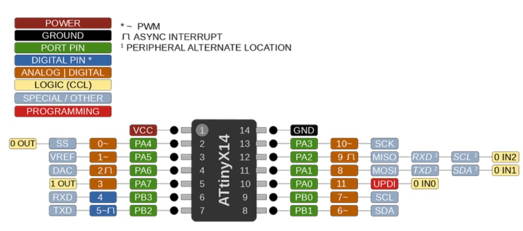
Pinout
Now this is the part that intrigues and interests me the most. First, that black dot on the top left of the
micro-controller pintout schematic helps know in which direction i should solder my microcontroller on my PCB.
There are different types of pins, and understand what each
can digest or offer is important.
So let’s dig into it.
VDDis the input supply.GNDis the GND.
this two pins allow us to power the micro-controller, passing though components.
-
PA0/RESET/UPDIis the pin that we use to program our microcontroller or reset it. (We use it to connect to the UPDI (Universal Phone Device Interface), which I had already designed in order to program my Attiny1614. -
PB0 | PB1 | PB2 | PB3 |PA0 | PA1 | PA2 | PA3 | PA4 | PA6 | PA7are input/output pins connected to input/output register.
Now why are some called Port.A and others Port.B?
That’s because it’s works with 8-bits.
So PortA.Dir(0000 0001) translates to PA0 being the
only pin with output.
That’s because in the datasheet, we understand that 1 is output, and 0 is no effect - output.
Electrical characteristics.
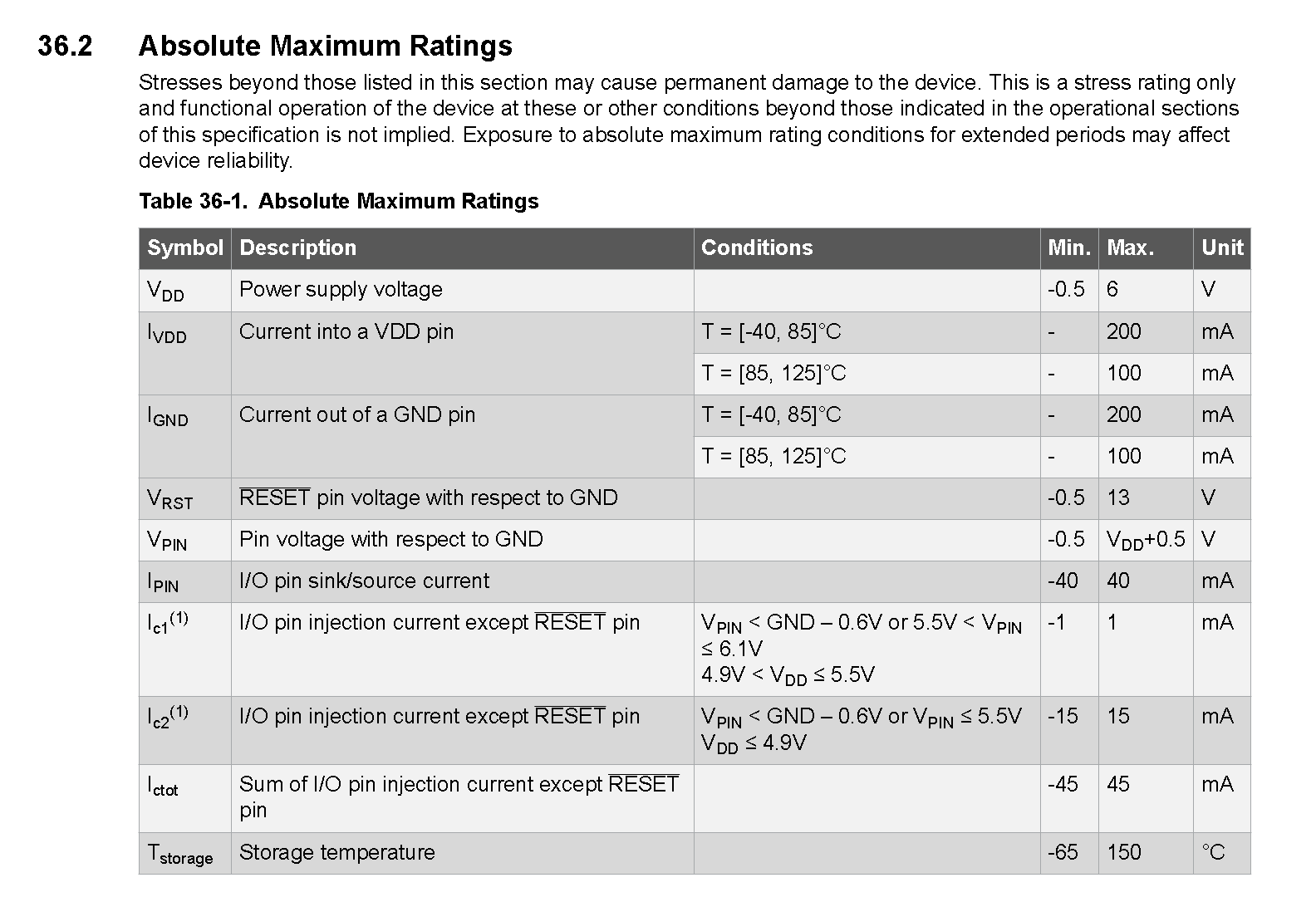
This is very important in order to understand how to
power up my microcontroller without burning it.
Usually, for the Attiny family, it could be 3.3 V or 5V, which fits with most conventions.
Though, on this chart, we can see that they present us with a range that goes between -0,5 V and 6 V. This range is given in order to prevent a disaster in case of a peak or a low.
Setting up my board.
In simple terms, I use: - an FTDI cable to power up my pomodoro -attiny1614 board. The board could be powered with anything else. - FTDI and UPDI PCBs in order to communicate with my board.
UPDI is the protocol of programming, which in a way allows to translate from FTDI to the attiny. It has a 4.9Kohm condensor that allows to merge the code exchange from Rx and Tx.
FTDI has a chip that allows us to push code between the attiny and arduino IDE.
Welcome to Arduino Integrated Development Environment
(Recommended)[https://www.youtube.com/watch?v=_h1m6R9YW8c]
I decided to start with Arduino IDE since it is C, simplified.
It makes it easy to communicate with different boards using libraries, and a simplified syntax.
1- Go to preferences and paste the link to the json file of the current board manager that wanna use.
2- The link allows us to look for the corresponding board manager. Go into the boards manager and download the megatinycore which includes my current board.
3- This will make it appear in the current list of boards. I select my attiny1614 that’s in the list.
Make sure you are not selecting Optiboot option That costed quite some time debugging.
4- I select the port to which my FTDI/UPDI combo is connect, not to be mistaken with the alimentation one.
5- Also, it is important to select the programmer we are using in order to communicate with the board.
This is also something that is included in the boards library downloaded.
5- Libraries will come my way in order to code specific data/components.
6- The clock is something to pay attention to depending on your inputs/outputs.
7- Always burn your bootloader when clock changes are made!
Arduino - pero muy basic.
As a first step, I just starting my blinking my four led lights.
Each one connected to a pin.
Red Led (R) connected to pin 6;
Green Led 1 (G1) connected to pin 8;
Green Led 2 (G2) connected to pin 9;
Green Led 3 (G3) connected to pin 10.
void setup() {
  // initialize digital pin LED_BUILTIN as an output.
  pinMode(6,OUTPUT);
  pinMode(8,OUTPUT);
  pinMode(9,OUTPUT);
  pinMode(10,OUTPUT);
}
// the loop function runs over and over again forever
void loop() {
  digitalWrite(6, HIGH);   // turn the LED on (HIGH is the voltage level)
  digitalWrite(8, HIGH);
  digitalWrite(9, HIGH);
  digitalWrite(10, HIGH);
  delay(1000);                       // wait for a second
  digitalWrite(6, LOW);
  digitalWrite(8, LOW);
  digitalWrite(9, LOW);
  digitalWrite(10, LOW); // turn the LED off by making the voltage LOW
  delay(500);                       // wait for a second
}
CC basic - pero tan basic.
I tested C, because it seemed like it is the base of everything Arduino is.
void setup() {
  // put your setup code here, to run once:
  PORTA.DIR = 0b00001110;
}

void loop() {
  // put your main code here, to run repeatedly:
  PORTA.OUT =  0b00001110;
  delay(1000);
  PORTA.OUT = 0b00000000;
  delay(500);
}
OR
void setup() {
  // put your setup code here, to run once:
  PORTA.DIR = 0b00001110;
}

void loop() {
  // put your main code here, to run repeatedly:PORTA.OUT =  0b00001110;
  PORTA.OUT =  14;
  delay(1000);
  PORTA.OUT = 0;
  delay(500);
}
Understanding basic terms of programming.
high and low
This video allowed to understand what high & low means.
In simple terms, high is when the signal goes beyond a set threshold.
In simplistic terms, if our analog signals oscillates between 0V & 5V, and the datasheet specifies the high to be between
3V and 5V, then this is when the signal is considered high.
High is one is ON is |.
Low is zero is OFF is O.
The topic is more complex and I hope that in the output and input weeks, I will be able to concretise better.
The differences between Vih(Input High), Voh(Output High), Vil(Output Low) & Vol(Output Low).
This sparkfun page will be a reference for me as we move forward.
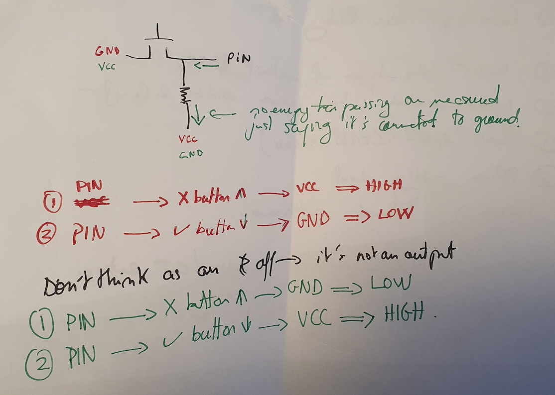
Buttons; not as simple as they sound.
This concept differs slightly when it comes to buttons.
Spoken about as a simple switch, they actually are not that simple.
This sketch helped me understand the concept of LOW & HIGH beyond on and off.
LOW and HIGH indicate what the pin reads from the button signal, depending on how the
polarity has been designed and produced.
Coding my Pomodoro.
It was quite a fun and interesting ride to understand how to code my pomodoro. I hope to expand on this section later on, but these are the main ideas I was able to concretise.
Defining constant integers & unknown values
First thing I need to do is define which component in linked to which pin.
const int B = 3;
// this translates to " I will assign the name B to the component linked to pin 3
int state = 0; // defines my initial state.
unsigned long previousMillis = 0; // defines value of previousMillis in the loop.
unsigned long blinkMillis = 1000; // defines value of blinkMillis in the loop.
int buttonState; // defines buttonState as integer/value.
bool buttonPressed = false; bool holds one of two values.
Void Setup
Within void setup, I set up the modes of my pins.
Are they inputs or outputs.
pinMode(B, INPUT);
The logic of my pomodoro can be divided into 8 different states.

It ended up working!
Learnings
-
Having a clean code with explanations in comments is
VERY MUCH IMPORTANT. Always keep your code clean, allow yourself to understand what you’re doing AND double-check each bit of code so you don’t fall into a turmoil of figuring out what to do. -
Personally, and I wish I knew this earlier, learn faster by using paper & pen. It allows me to set up the logic before getting to the hands-on with the softwares and code.