04. Electronics Production
This week I worked on defining my final project idea and started to getting used to the documentation process.
File Preparation 101: Step by step guide
I started by downloading the .png of my programmer for milling. Two files, one is the exterior outline to be able to cut, ironically called “interior” for which we will use the 1/32 mill. And then the interior lines called “traces” which are milled with the 1/64 one. I am producing a CMSIS, and a SWD that will allow to ‘transform” the 10 pin SWD component into a 4 pin one.
- I specify on this online software which milling machine I am using and the file type I am using.

- a module opens for me to upload the .png file. I upload the CMSIS .png file.
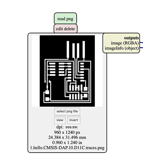
The dpi is important for the milling machine software to read well the lines. the dimensions in mm are also important, especially when milling more than one programmer on the same board. My CMSIS is approx. 25 x 32 mm. I will need this measurement later on for preparing the .rml file of the SWD.
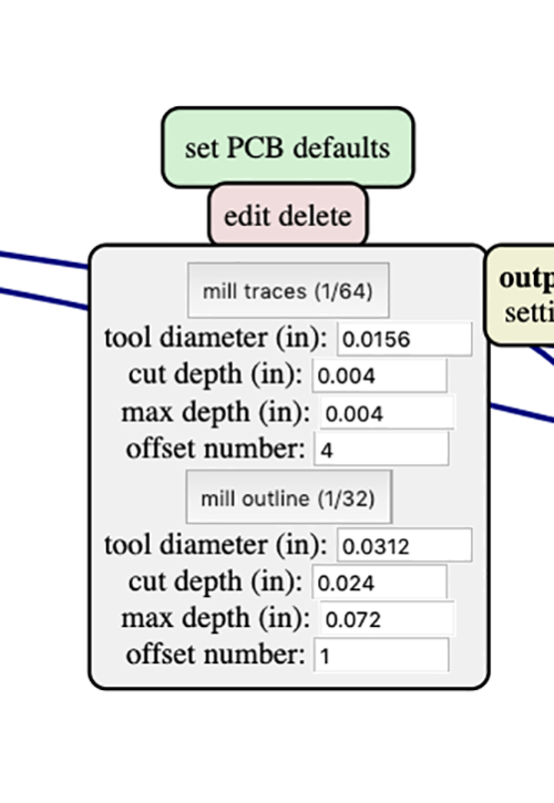
- In the PCB settings, I make sure the mill 1/64 is selected; as it does thinner cuts for the traces. In the external trace, I will choose the 1/32 since I will want to cut the programmer following those lines.
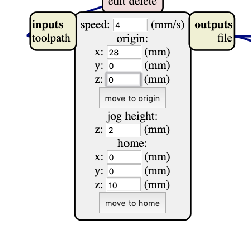
- After that comes the origin and home setting. These are very important to avoid scratching our programmers.
The origin defines where the milling starts.
The home is where the miller goes back after finishing working on the first file.
They are defined according to 3 axis; x, y & z.
The job height is the height the mill rises to in order to move from one point to another while working on the same file.
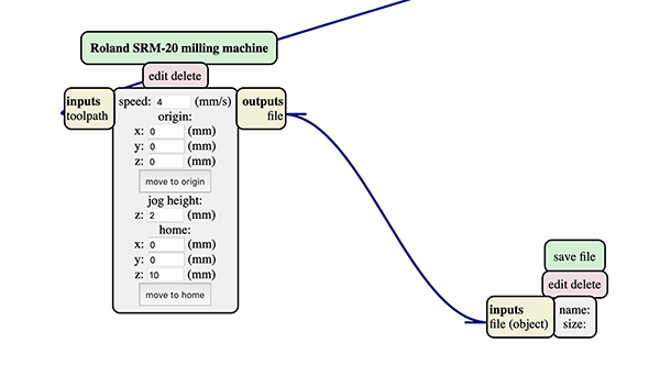
IMPORTANT: The Z of the home should NEVER be 0 mm, because it would scratch the work after finishing.
- After that being set, and since my laptop is not connected to the milling machine, I delete the web module & I open a save module instead.
- I then let mods calculate the trajectory it needs to take. The blue indicate milling, the red indicates the trajectory it takes away from the board to move from one point to the other.
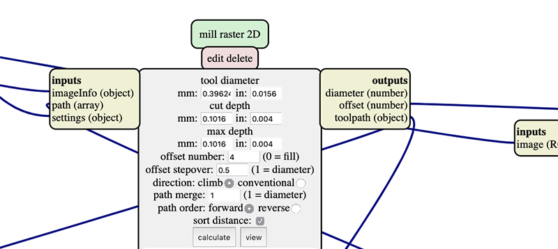
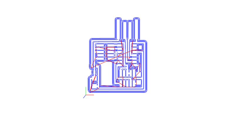
The .rml file directly downloads on my computer.
- The same process is done for the external trace, while making sure to change the milling setting from 1/64 to 1/32.
File Preparation 102: How to place multiple files in one
Though in my final production I won’t need to produce the SWD programmer, i think it is quite important to know how to set the file up.
-
First, I measure the copper board I am using. It is 75x50 mm.
-
Second, I recall that my CMSIS has approx. 25 x 32 mm.
-
I make the following sketch to locate exactly where my SWD programmer can start.
By keeping a 3mm margin, I can safely mill my 2nd programmer.
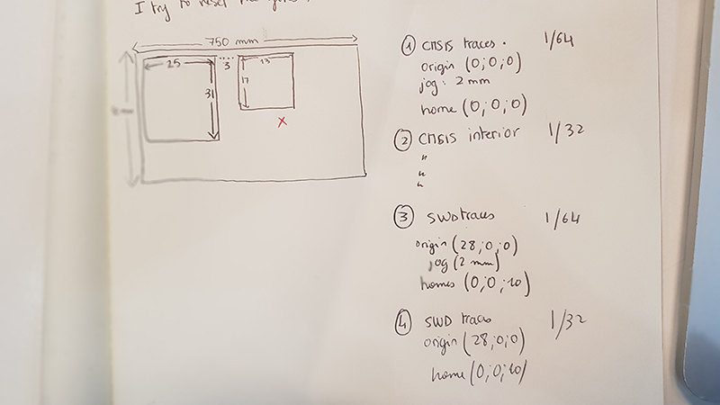
- It is now time to set up the origin of my second programmer. I also make sure the home z is not 0 to avoid any scratching.
Using the Roland SRM20
I should set up my mill before milling. That mainly needs to set up:
- Fixing the copper board in the milling machine
- Placing the adequate mill.
- the x,y & z first origin on the machine.
- Uploading the traces
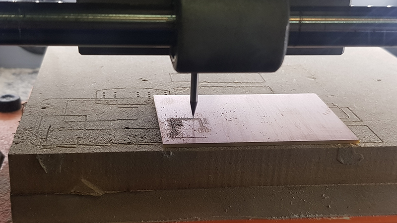
To fix the copper board, I use double tape & make sure no finger traces are there.
- I start with internal traces, and therefore use the 1/64 mill.
- I loosen the screw in order to place in the mill, still protected with a piece of plastic.
- I set up the x & y using the machine’s software; a pretty straightforward interface to use.
- I slowly lower the Z until it is fairly close from the copper board.
- I then remove the protection, loosen the mill WHILE HOLDING IT WITH MY FINGERS, until it touches the copper board.
- I tighten the mill again and do a test. It works.
- I press cut and open the files
- I repeat the process with the 1/32 mill for the external traces.
ERROR & TRIAL
- When I start soldering, I realise that the traces were not well milled, leaving thin connections that I tried to clean with a cutter. That ruined the circuit. I had to do it again.
Lesson: always check the milling is well executed to avoid such situations until you get better with your tools.
- The powder in the milling machine made the board slip as the external trace was being milled. Luckily, I was right there to pause it instantly.
Luckily, I was able to rerun the cut by setting the home based on the milling test done. I restart the external trace milling.
Lesson: Clean the milling board with a brush & make sure your board is will-fixed!
Soldering
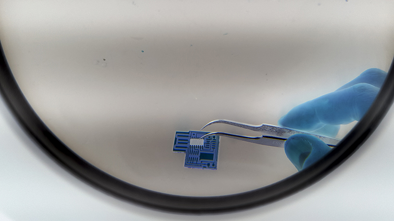
Though Soldering was the step I was most afraid of, it was the most relaxing & meditative. I enjoyed it a lot.
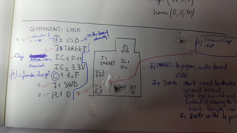
I needed the following: - a magnifier - tweezers - my shopping list** - copper - solder - the final programmer for polarization or a picture of it!
Lessons learned: patience, paying attention to polarization, & music!

** I did my shopping list in a way that visualises the positions of my components so I do not get lost during the process.
Programming my programmer.
Easy way to explain what was happening is with the following narrative: My CMSIS will eventually grow up to be a programmer. To get there, it should learn how to be one.
There are many languages it still doesn’t understand, including the USB language. This is why, to let it become a programmer, we should flash it.
How do we do that?
By feeding it a binary system that was luckily provided by Neil.
But instead of feeding, we call this compile it
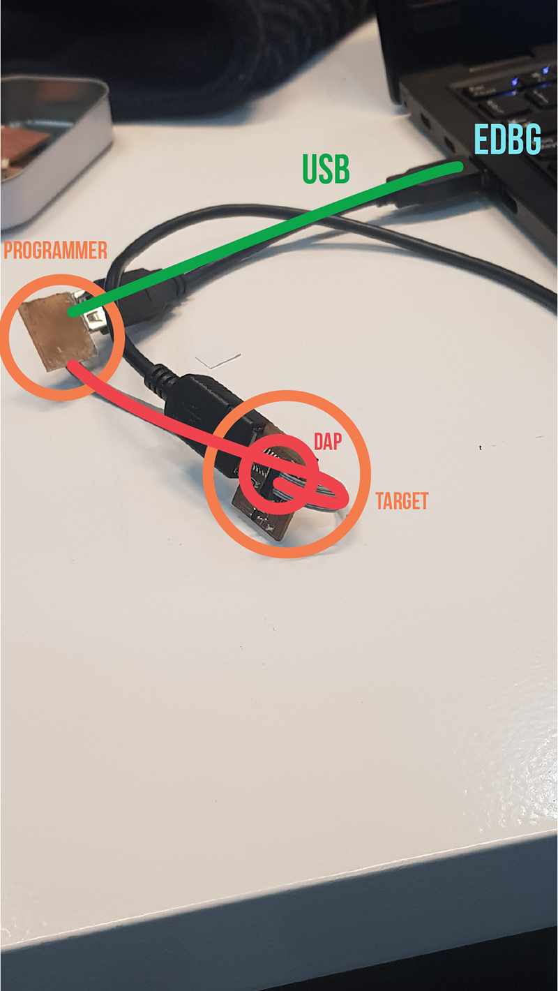
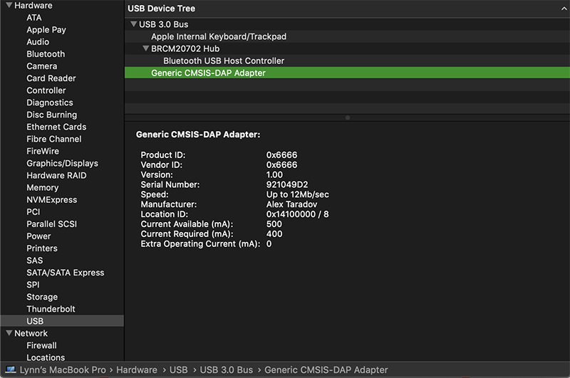
To do so, I connected my CMSIS card to an already programmed one.
My CMSIS is the target.
The programmed one is the programmer.
In the terminal, we pip install edbg
Using EDBG, we feed the binary code that would allow to compile our target by writing sudo ./edbg -t samd11 -bpv -f free_dap_d11c_mini.bin -s B9D6FD92
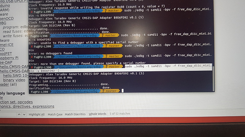
which translates to force compiling the target the binary code samd11 -bpv -f free_dap_d11c_mini.bin
through the programmer/debugger -s B9D6FD92
It worked!
Working files
- RML & PNG files for CMSIS 10 & CWD

Testing the compact milling machine
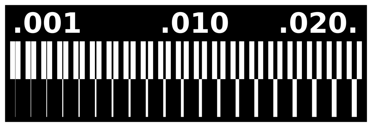
The goal of this group assignment is for us to know the potential gaps between our traces, or how thin the traces could be. Since the machines were always occupied and the booking system at Fab Lab Barcelona was not really effective, our class couldn’t have a chance to do many group tests. In the end, we were able to finish only 1 group test with the participation of the whole class.
We used the Roland MonoFab SRM-20 machine to mill a test file.
Detailed specs of the machine:
- Work area: 203 x 152 x 60mm
- Loadable workpiece weight: 2kg
- Operating speed: 6mm/min - 1,800mm/min
- Spindle speed: 3,000 – 7,000rpm
- Input Format : RML-1
- Material: Modeling Wax, Chemical Wood, Foam, Acrylic, PCB
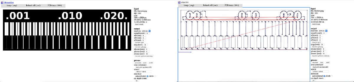
We prepared the .rml files using
- Select
.pnginput format and load the .png file - Select
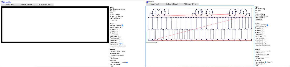
.rmloutput format - Select the proper process: PCB traces (1/64) or PCB outline (1/32). This will define the cut depth (0.1mm for milling traces and 0.6mm for cutting).
- Select
SRM-20in the output machine. - Modify settings to origin 0,0,0 (x,y,z);
zjog = 12(to make sure the milling bit will be lifted up while moving across the workpiece and avoid damaging both the traces and the fragile bit itself); and home 0,0,12 (x,y,z). - Select the proper direction. If there are thin traces on the board, we need to select the conventional direction in order to avoid broken traces.
- Click the calculate button to calculate the toolpath and click the save button to save the
.rmlfile.