14. Networking and communications
Goal of the week:
- design, build, and connect wired or wireless node(s) with network or bus addresses
What is a communication protocol?
Before starting to describe the I2C communication protocol in detail, it is useful to clarify what, in general, a communication protocol is.
To understand better, I used this tutorial.
Put simply, a communication protocol consists of a set of rules that allow communication between devices. To better understand this point, we can think, more simply, of the rules that govern any conversation between human beings: every time we start talking to a person, we implicitly adhere to a series of rules such as speaking the same language, respecting the timing of not speaking at the same time, etc.
Some examples of well-known protocols are: + USB (Universal Serial Bus): regulates communications between a PC and its peripherals; + http (HyperText Transfer Protocol): used for the transmission of information on the Web; + TCP/IP: set of protocols for computer networks (including http and Ethernet) + Ethernet: protocol for communication within local area networks.
I²C communication protocol, also written as I2C (Inter-Integrated Circuit), is a synchronous serial communication protocol created by Philips in 1982 that allows many devices to exchange data with each other using only two wires, one for data and one to synchronise communication. It’s also called TWI (two wires interface) and uses only few wires:
- SDA (serial data)
- SCL (serial clock)
- VCC
- GND
In general, there are 4 distinct modes of operation:
- a master transmits - controls the clock and sends data to the slaves
- a master receives - controls the clock and receives data from the slave
- a slave transmits - the device does not control the clock and sends data to the master
- a slave receives - the device does not control the clock and receives data from the master.
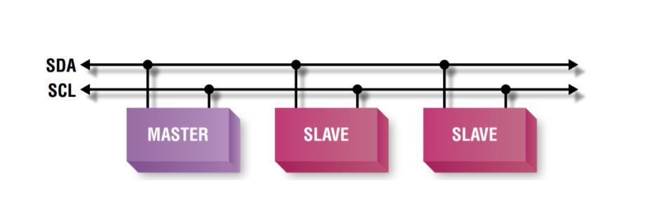
The Master device is simply the device that controls the bus at a given time; this device controls the clock signal and generates the START and STOP signals.
Slave devices simply “listen” to the bus, receiving data from the master or sending data if the master requests it. request.
An elementary sequence of reading or writing data between master and slave follows the following order:
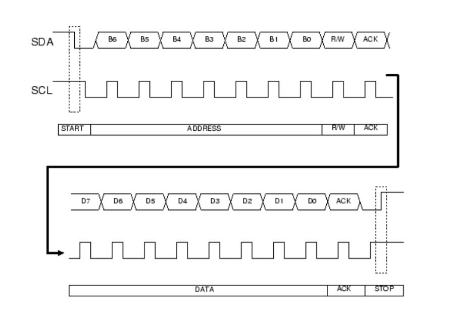
- Sending of the START bit (S) by the master
- Sending of the slave address (ADDR)7 by the master
- Sending of the Read (R) or Write (W) bit, which are worth 1 and 0 respectively (always by the master).
- Waiting for/sending of the Acknowledge bit (ACK)
- Sending/receiving the data byte (DATA)
- Waiting for/sending the Acknowledge bit (ACK)
- Sending the STOP bit (P) by the master
Steps 5 and 6 can be repeated to read or write more bytes.
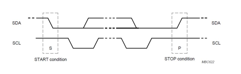
So, a communication takes place within two signal sequences that the master will send on the I²C bus, these are the START and STOP command. The basic rule is that in data transmission, the SDA signal can only change state while the SCL signal is low, and its value is then read during the rising or falling edge of the SCL signal becoming high. If the SDA signal changes value while SCL is high, it means that the master is not transmitting or receiving data, but is starting or ending communication, through the start and stop commands.
In a serial communication it is necessary to communicate the correct reception of data; this task is accomplished by sending an acknowledgement bit from the device that has correctly received the byte.
On the I2C bus there can be up to 8 devices connected, the master is the one that starts the transmission through the START command, but how does it establish which is the slave to communicate with? It does this by sending a sequence of 8 bits, the first 7 of which represent the device address, to which one and only one of the other devices will respond. The device address of a device connected to the bus must be unique.
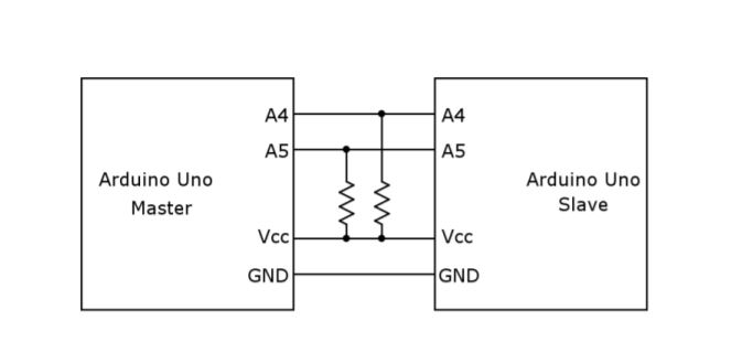
Instead, a master and a slave (or several slaves) are used, all connected using the same system. Each slave has its own address and is the master that can query and exchange data with all devices. On the Arduino, SDA and SCL are located on pins A4 and A5.
ARDUINO/ARDUINO COMMUNICATION
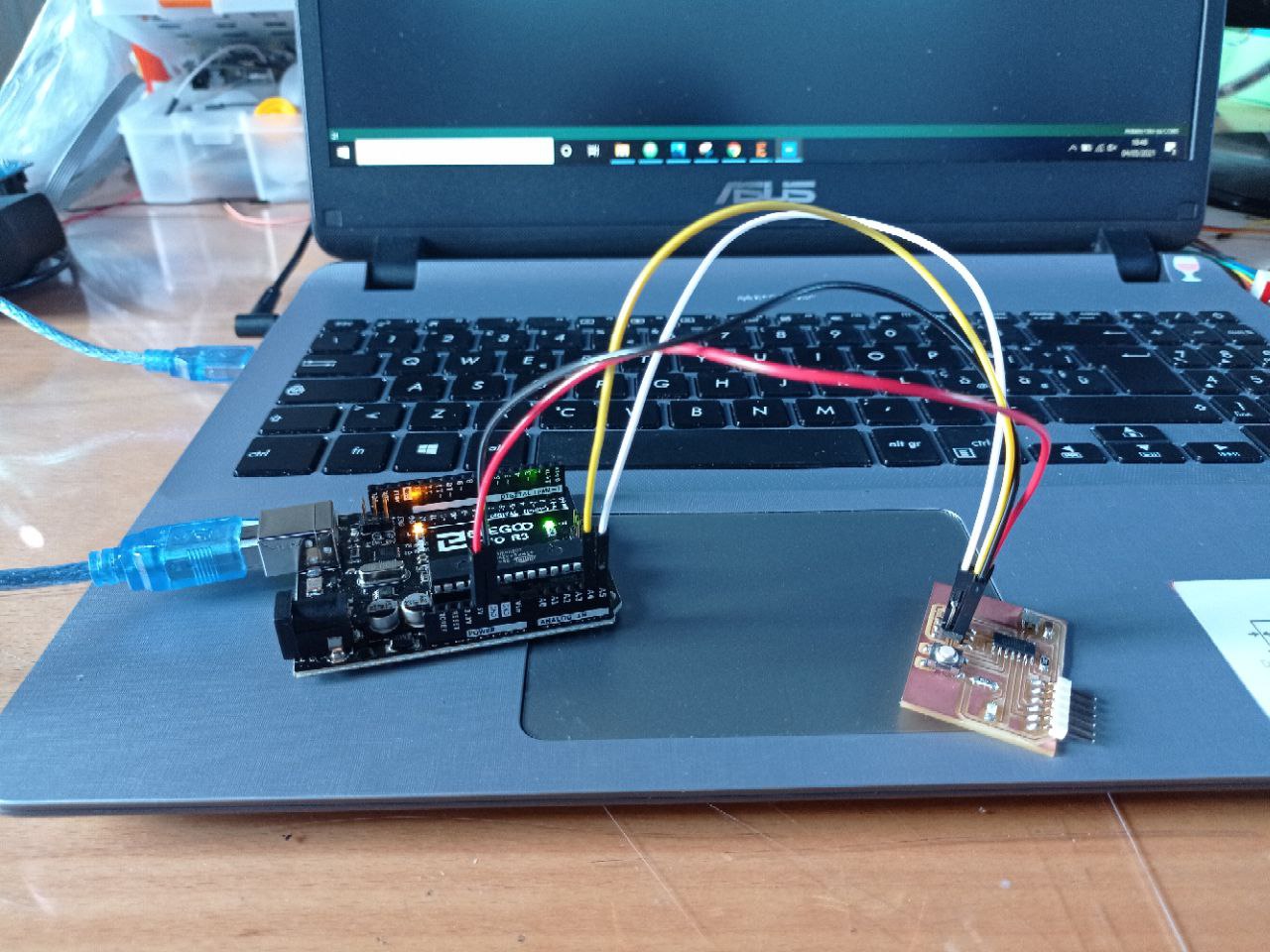
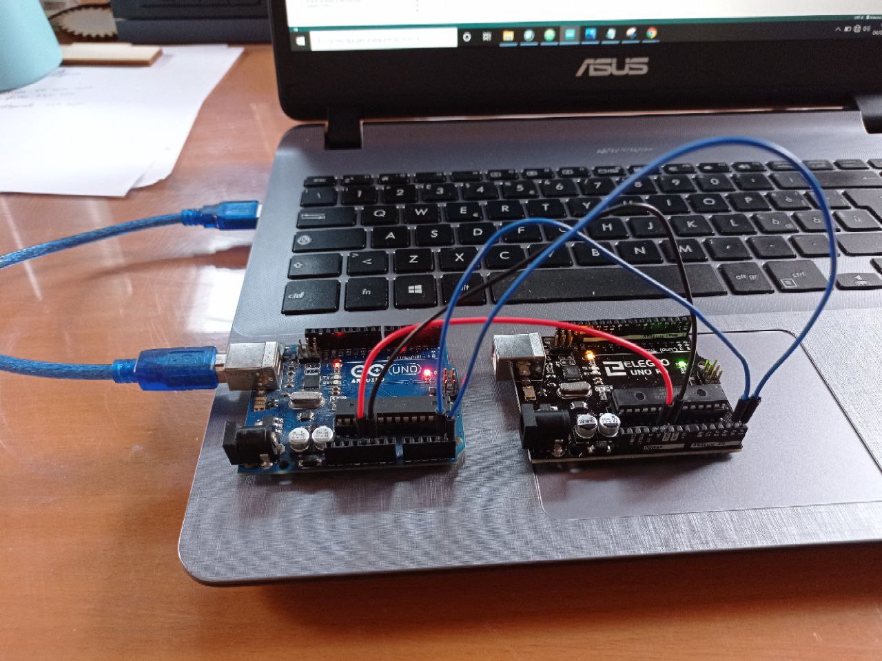
After studied what is a I2C communication I did my first attempt connecting two Arduinos. I used this tutorial to understand how this could work.
To connect two Arduinos, simply connect SCL and SDA to each other. You also need to connect the ground and power the Slave by connecting it to the 5V of the master. To provide greater stability, connect the two buses with two 1.5k resistors at 5 V.
CODING
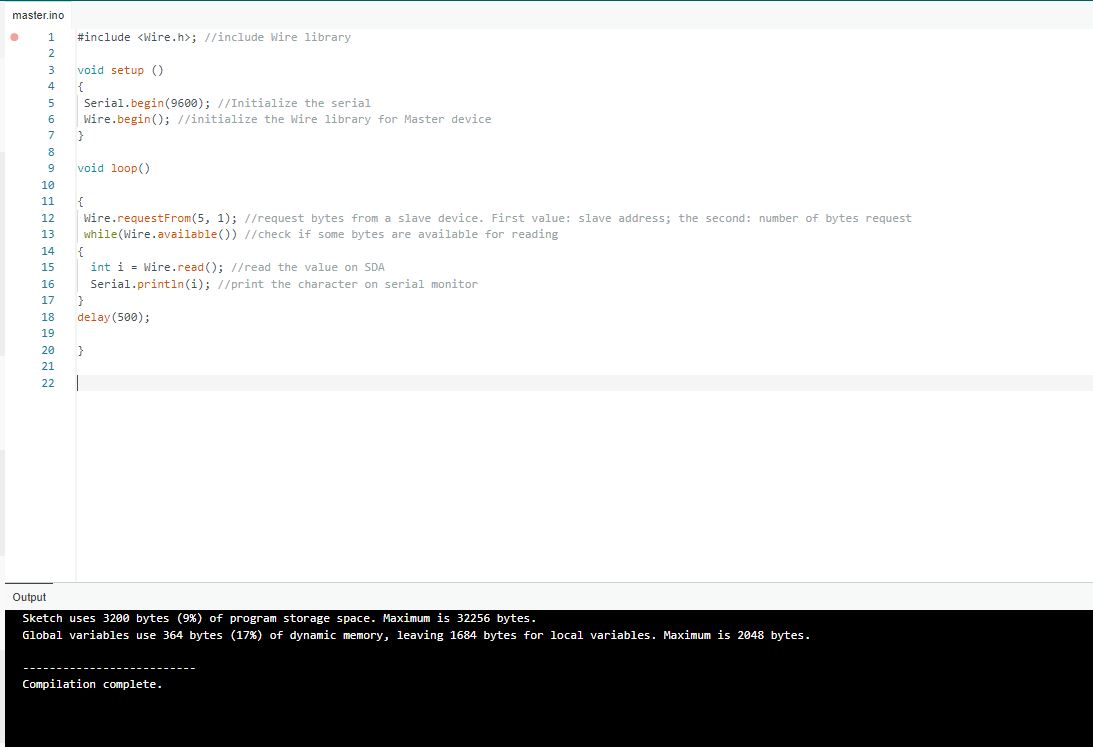
To program the two board you need to use two different codes: one for the Master and the other for the slave. I used this code for my Arduino Master:
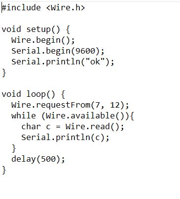
Let’s try to explain what is happening!
At the beginning it’s necessary to initialize the Wire library.
In Setup you initialize it with Wire.begin. At this point, you are going to decide whether it will work as a master or slave/client. Infact if you are not putting any number in the bracket it will be a master.
Then you initialize the Serial Monitor to see what happens in the communication.
In the Loop the master commands the slave to give it data. If you don’t have the slave yet the master will make a Wire.requestFrom (slave number, byte) request.
To read the sending data: while (Wire.available) is used. The sketch will be waiting for data and if data arrive with the command char c = Wire.read() it receives data and prints it on the serial monitor with the command Serial.println(c)
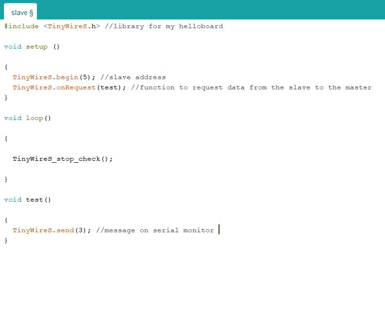
For the Slave Code I used the following one:
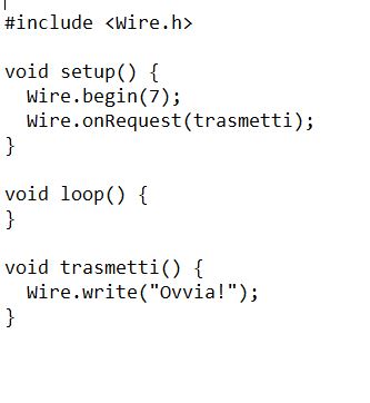
Again it’s necessary initialize the Wire library. In the Setup: “Wire.begin(Slave number)” and “Wire.onrequest(transmit)”. Transmit is the name of the function that has no parameters and returns nothing but takes care of sending the data that the master is receiving. It will transmit it in the Loop with Wire.write(“message”)
HELLO BOARD/ARDUINO COMMUNICATION
My second attempt included the use of my hello board and Arduino.
Before starting writing the codes, I installed the libraries on Arduino IDE. The needed library was the TinyWire, which is the same as the Wires one but it works on the ATtiny microcontrollers, to summarize I needed TinyWireM for master board and TinyWireS for the slave one. The first library it can be installed directly via Arduino IDE. The second, is not included in the available libraries, so I downloaded it here. Then, I imported the Zip file inside the Arduino folder. I had some problem in this step because the Arduino IDE wouldn’t recognize the library so I had to delete the program and reinstall everything again but finally it works.
After this step, I was ready to write the two codes.
I connect my Arduino and I used a master code:
After that I uploaded the slave code on the hello board:
I then connected the master/slave and the message appeared on the serial monitor: