6. Electronics design
Goals of the week:
- Redraw the echo hello-world board, add (at least) a button and LED (with current-limiting resistor), check the design rules, and make it
Design
This week the task was to redesign a board with PCB Design software. I chose to use Eagle. Our instructor gave us a brief introduction to the capabilities of the software, which I found to be quite intuitive, although with some flaws in simple actions such as deleting lines, which frustrated me a bit.
After choosing the board that I wanted to redesign (link), I opened Eagle and I inserted the fab libraries inside so that I could easily find the components. I downloaded the library and put it in the “libraries” folder on my computer. After activating its use (a small green dot appears in front of the library name), I chose all the components that I could use to create the schematic, adding a button, a led and the resistor to be placed together with the led to control the passage of current and prevent it from burning out.
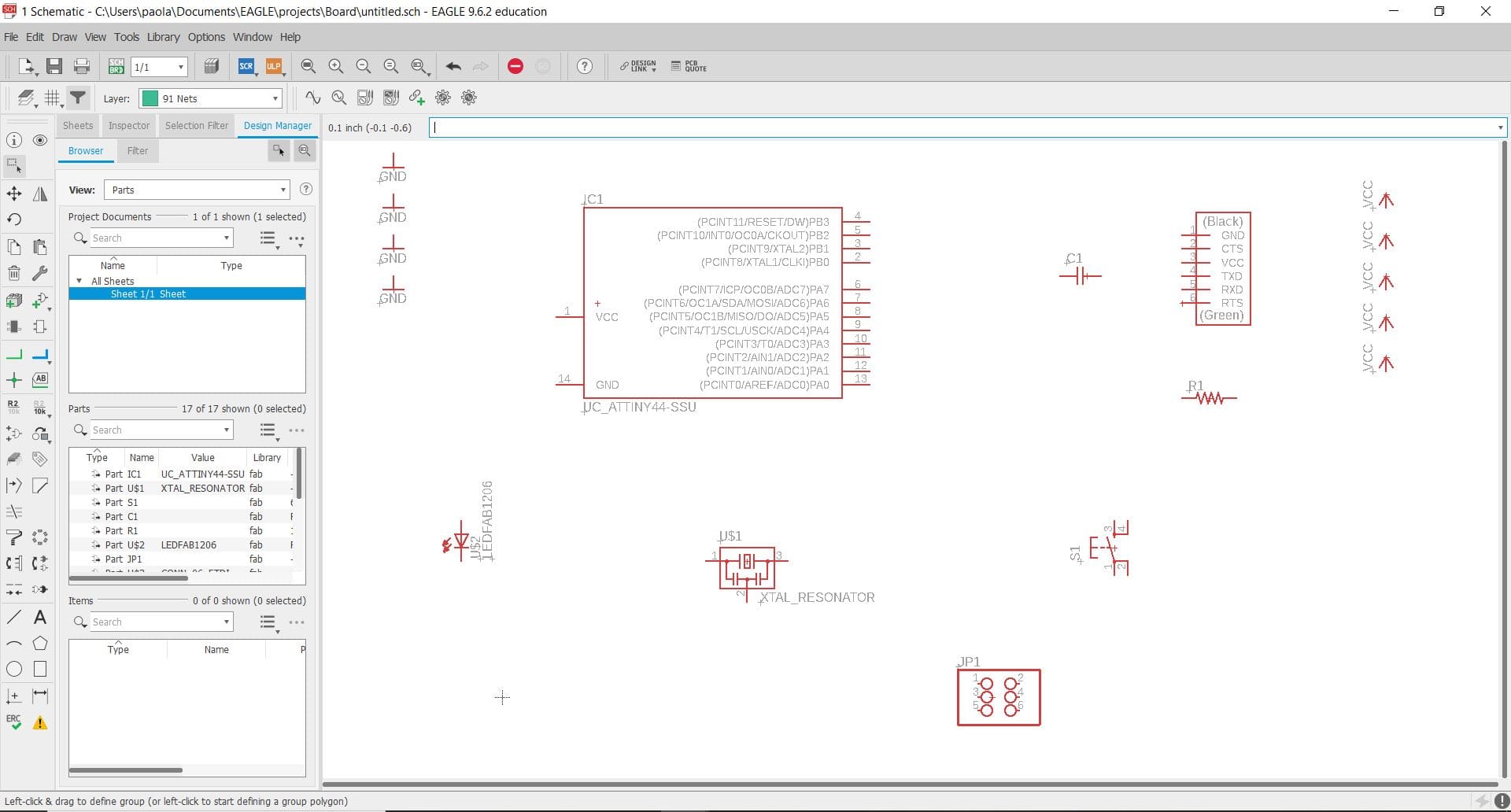
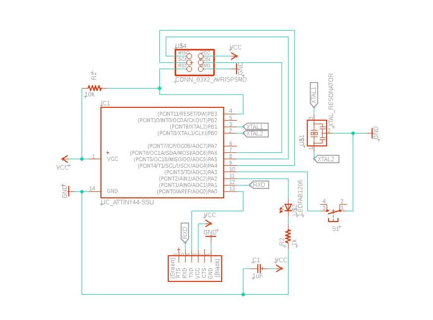
In the schematic, to facilitate the arrangement of the components, it is advisable to use labels to avoid unclear visibility and too many confusing nods. I also chose the value for some components such as the capacitor and the resistor. To do that, I read some information on the component’s data sheet.
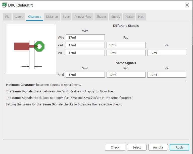
After making the schematic, I moved to the board window where I started working on the physical layout of my PCB. First, I set the grid to a value of 17 and enabled the dots for easy visibility. I also set the Design Rules (Design Rule Check” tool or DRC) in particular the “clearance” to a value of 17 mil (according to the end mill of our SRM-20).
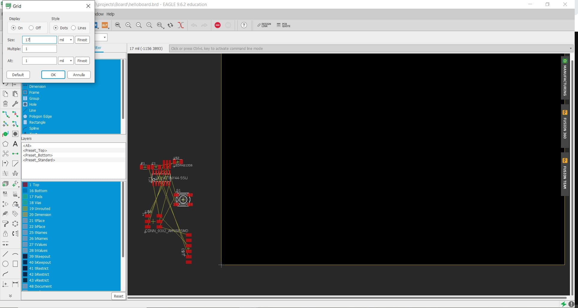
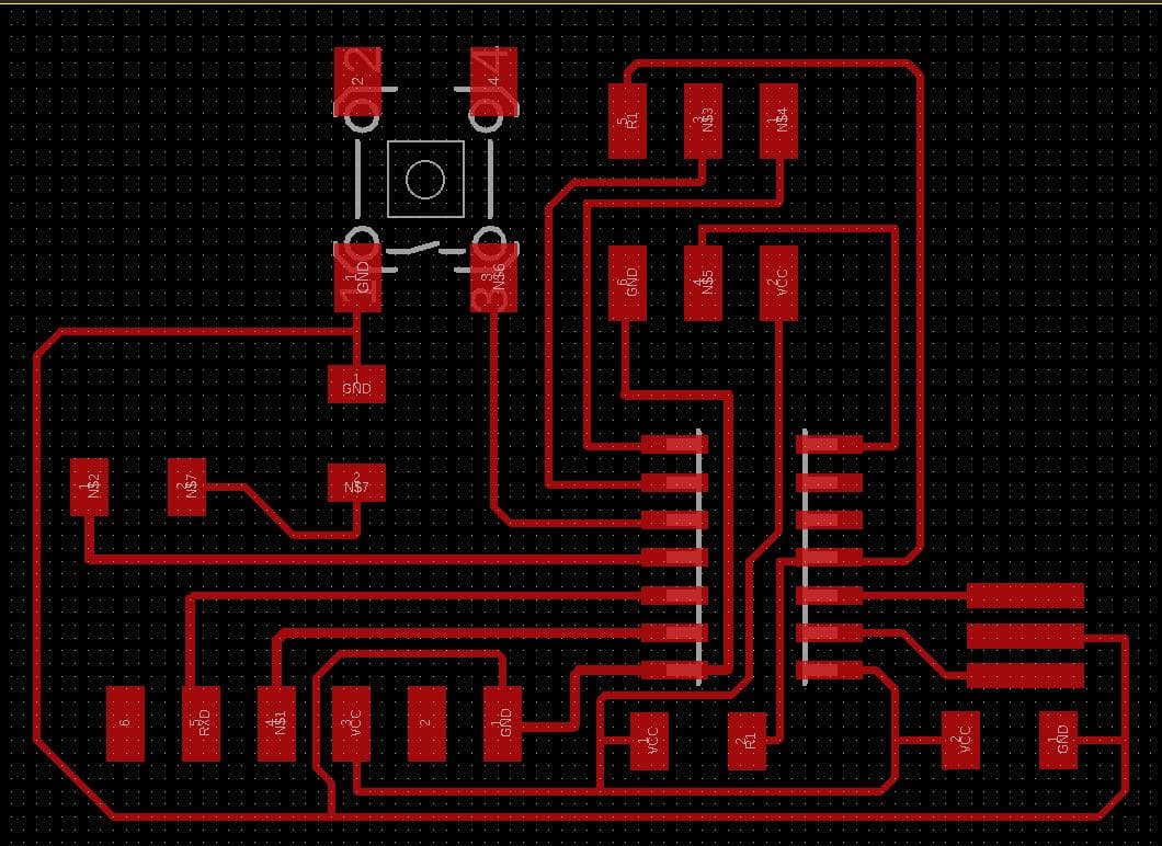
At this point, all the components are arranged in a cluttered and unintelligible manner. So I tried to arrange them in such a way that it was easy enough to connect them together. I certainly didn’t choose the easiest way, but it might be appreciated for its originality!
After several hours of trying to connect them all I managed to achieve my goal:
At this point, it was necessary to prepare the files for the milling machine.
First of all I exported the png from Eagle by deactivating some layers and thus leaving only the basic design without writing.
After this operation, I opened the file in GIMP. With the canvas size option I added 100 px to the outer border to make sure there was enough space.
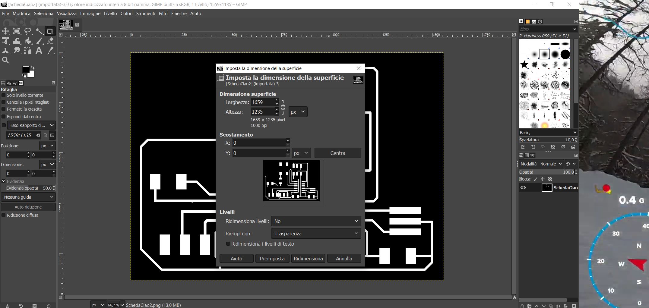
I added a new layer to create the black border for printing the traces. I then re-used the same layer for the outline file to create a white rectangle with a black outer border.


After saving the files, I loaded them into the mods, changed the source settings and downloaded the readable files for the milling machine.
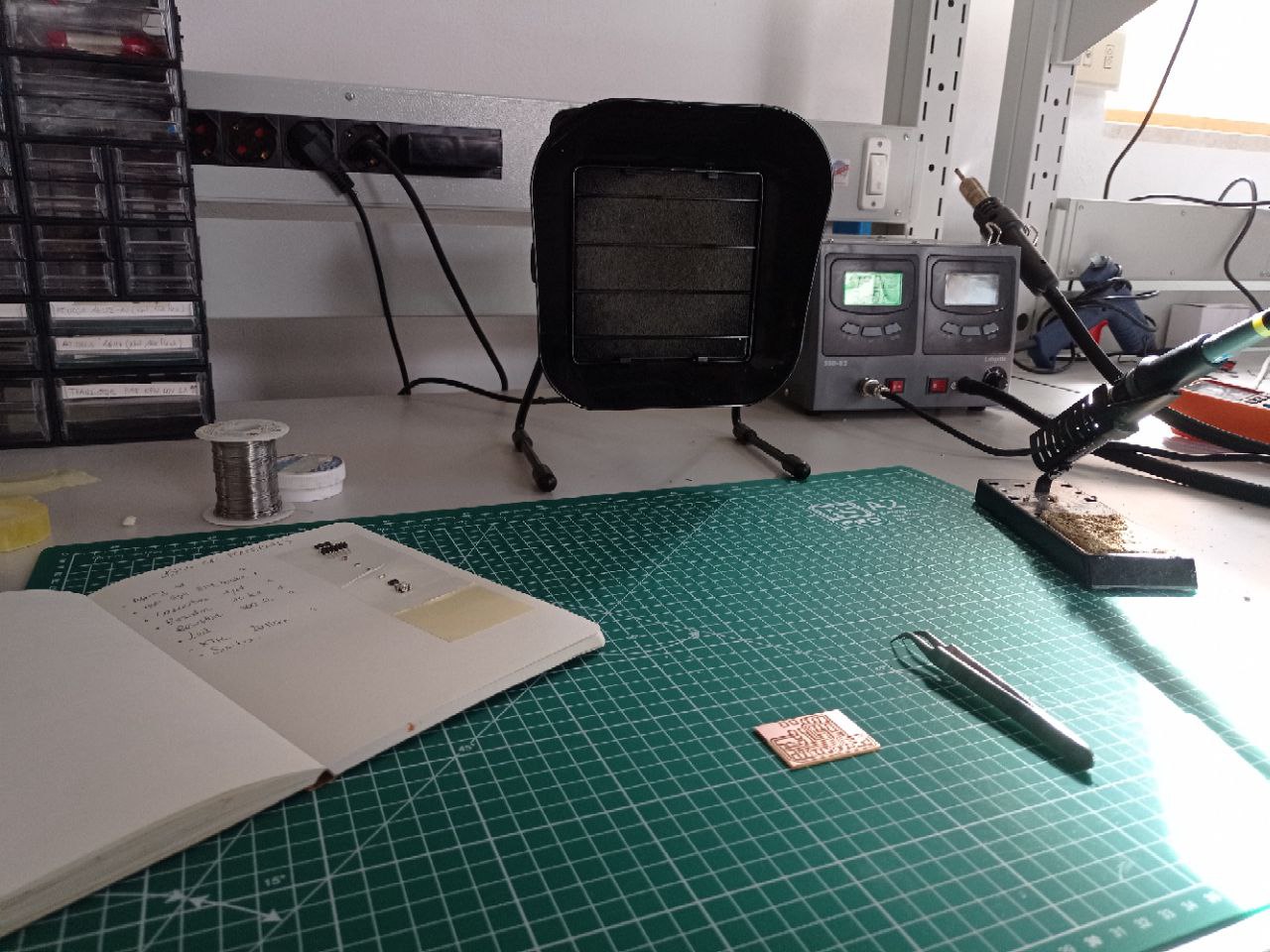
Milling and Soldering
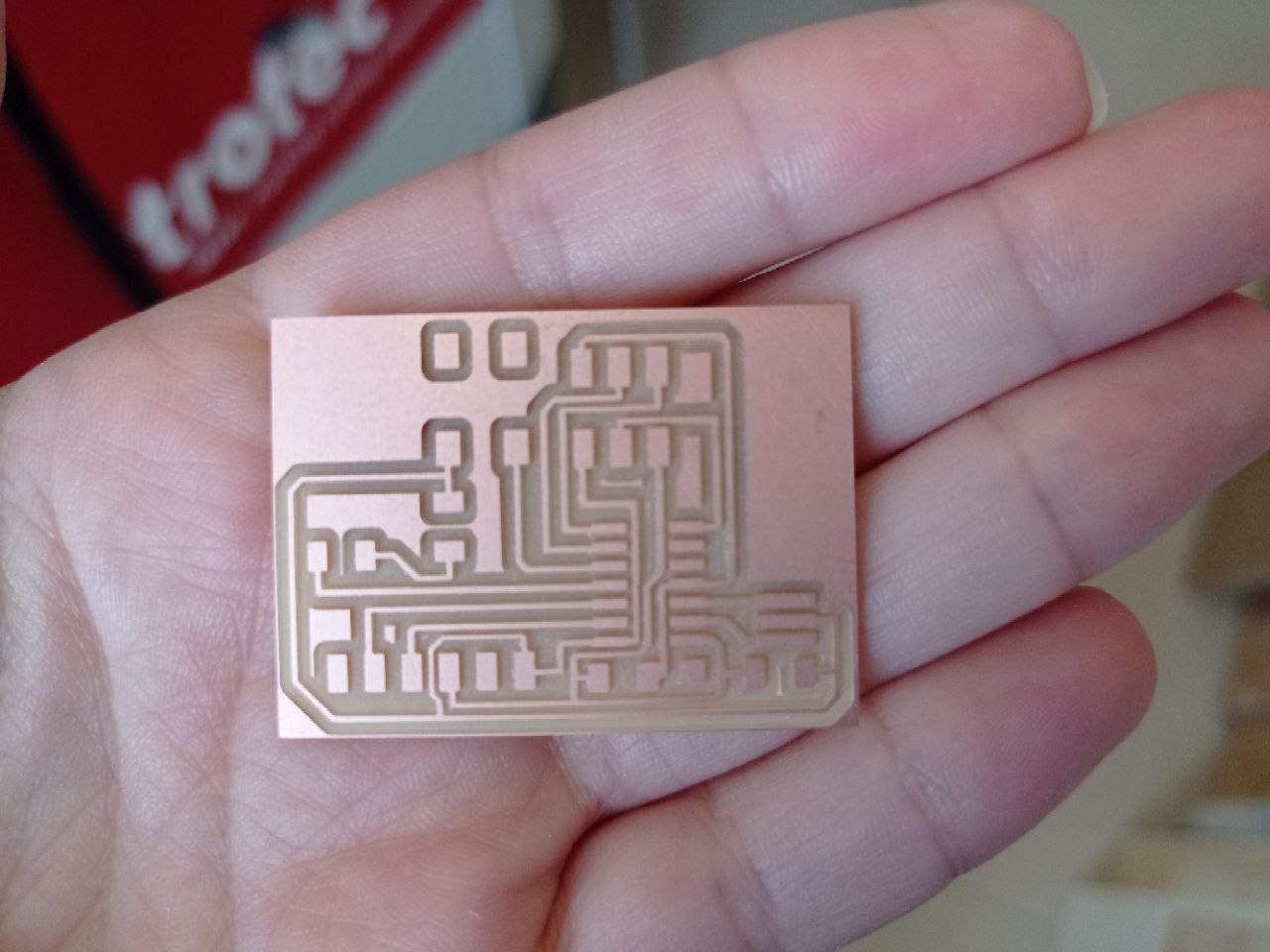
Despite the fear of having to make countless attempts as in week 4, I managed to mill without any problem and get my shiny board at the first attempt:
I then retrieved all the components I needed for soldering and wrote my bill of materials. I started soldering and everything went well.
The only problem I had was that I didn’t check the position of the button so I had to desolder it and then reposition it in the right direction.
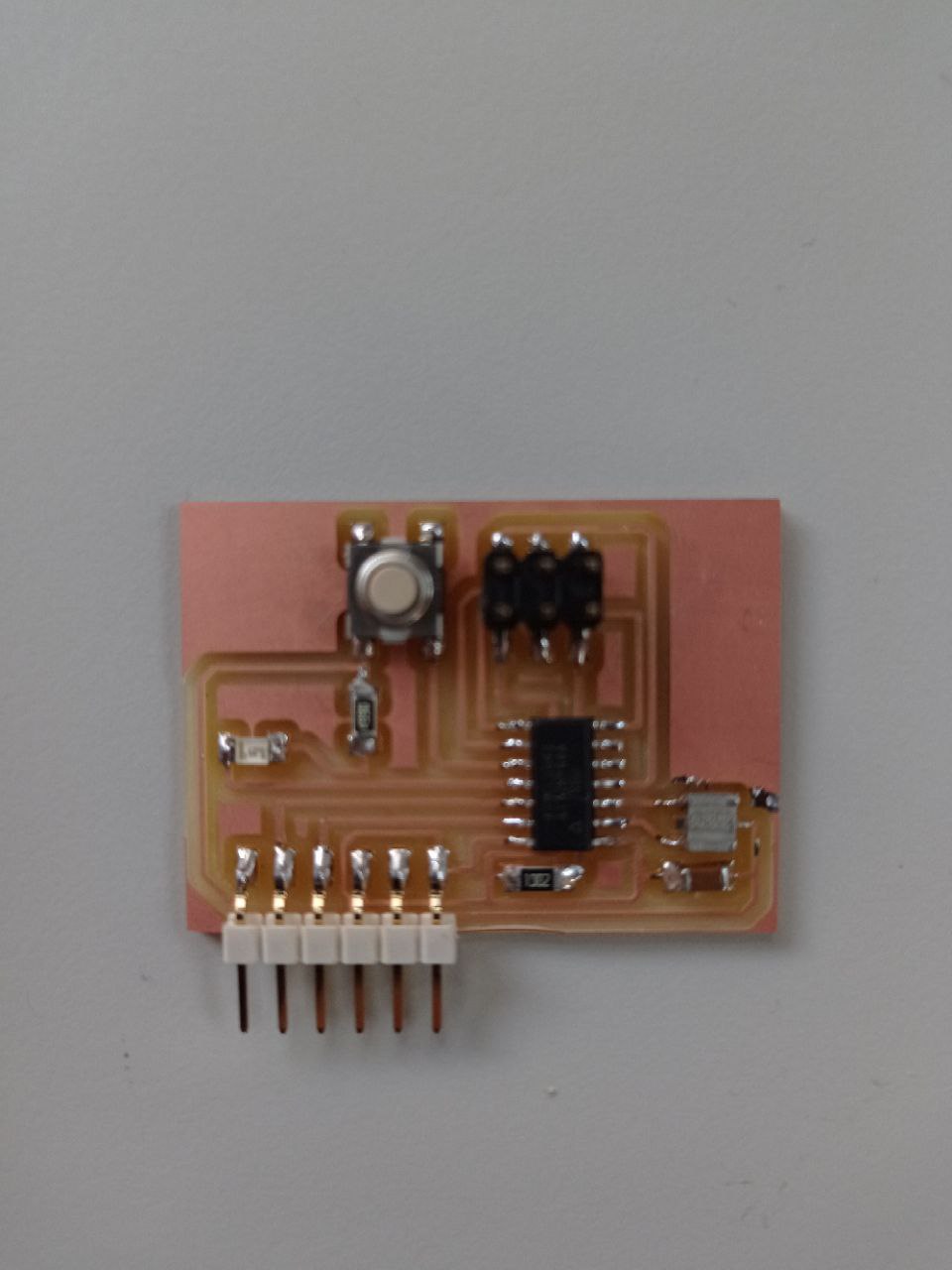
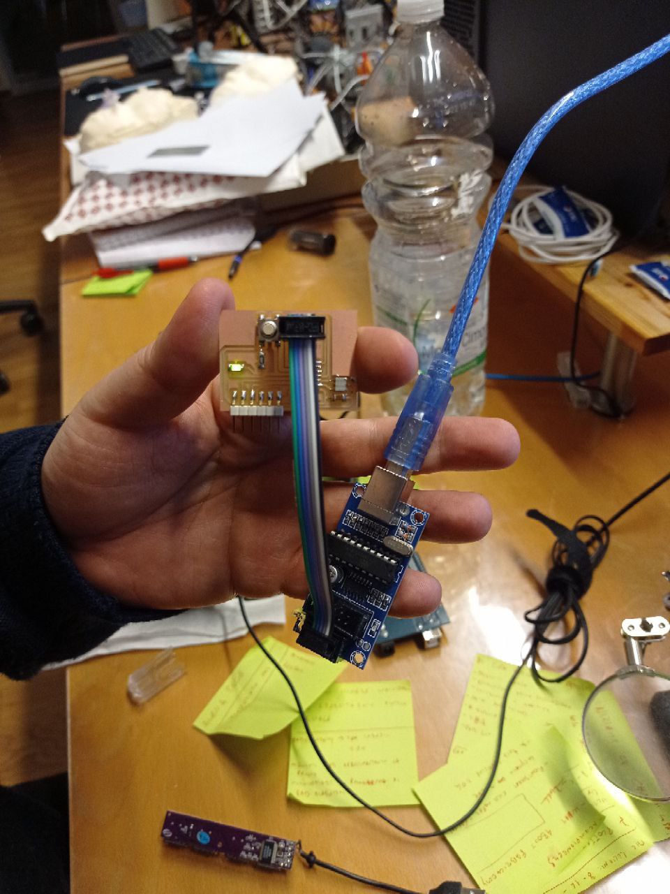
Finally, I programmed the PCB and tadaaaaan… blink of the LED.
Well, I survived at this week too.