7. Computer controlled machining
Goals of the week:
- Make (design+mill+assemble) something big
DESIGN
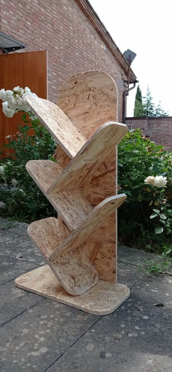
For this assignment I decided to create a bookcase with shelves placed perpendicular to each other.
The model is therefore composed of
- base
- wall
- 5 shelves
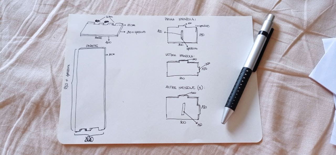
I drew each element in a different sketch, then I extruded it giving it the thickness of wood (11 mm) and from the bodies I created the components thanks to which I assembled the 3D model to verify the correctness of the intersections I had created. After joining everything, I used the function Combine to go and create the pockets in what are the points where the pieces will be joined together.
The model I created on fusion is as follows:
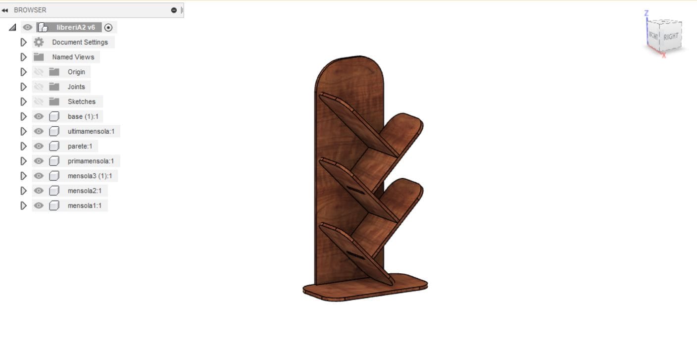
I then exported the individual DXF files to proceed with the milling phase.
MILLING
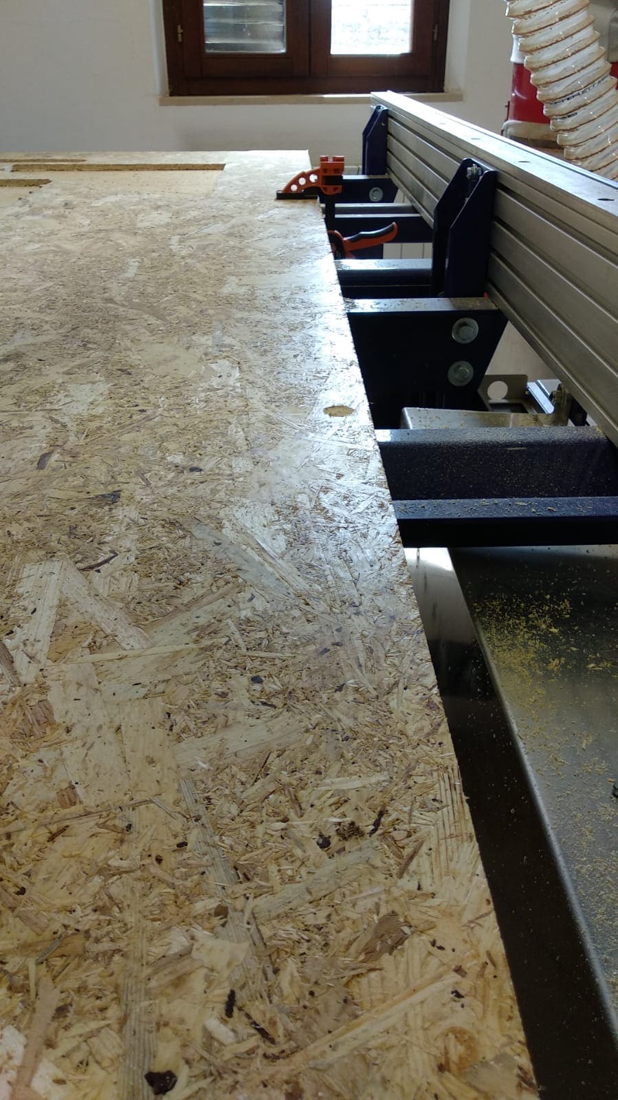
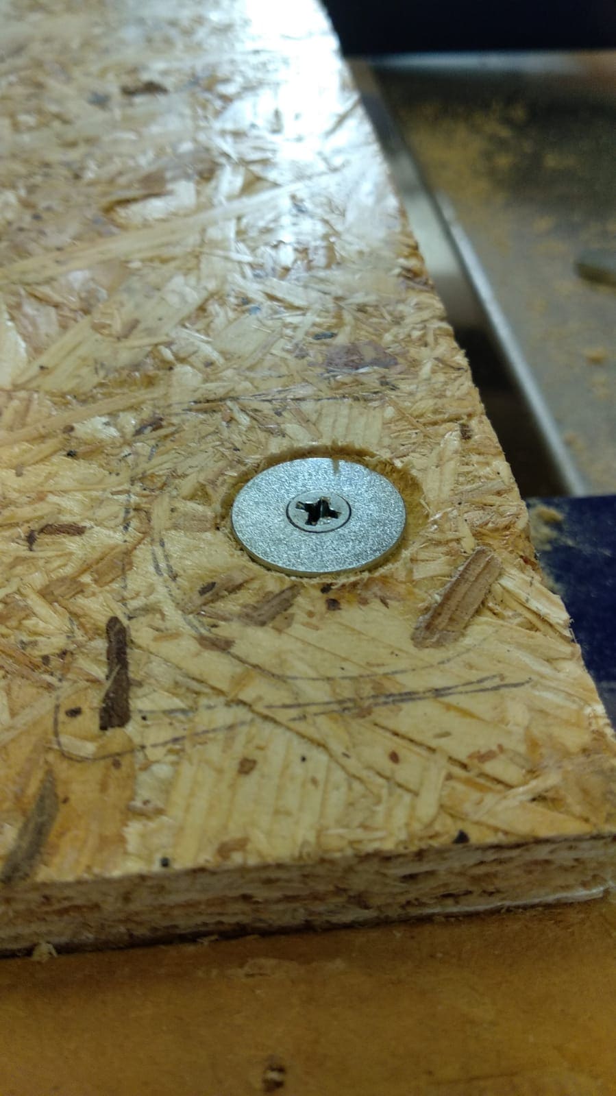
The program used for milling was V Carve Pro. Before setting up the program, however, it is necessary to set up the wooden board and secure it with screws to prevent it from moving freely during cutting.
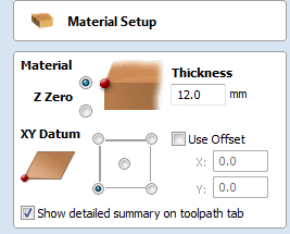
The initial settings are for material thickness and work surface size. It is also necessary to indicate where we intend to set the origin of the work.
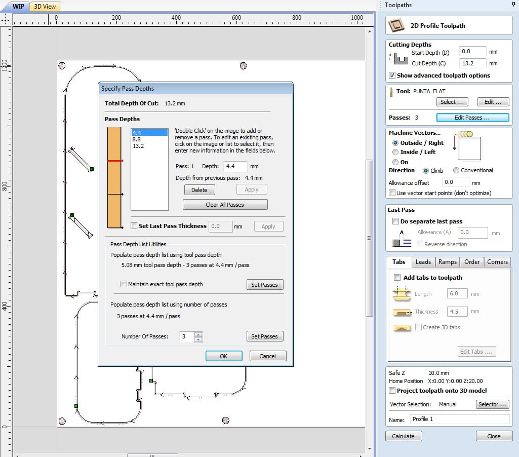
Then I set the Cut depth, the tool to be used for cutting and the number of passes the drill must make to cut the material which in my case, given the thickness of the material (11 mm) was 3 passes.
I then set up the T-Bones (Drawing>Create Fillet>T-Bone Fillet). This fillet are used for creating clearance in internal corners to when the slot is the same size of the tool.
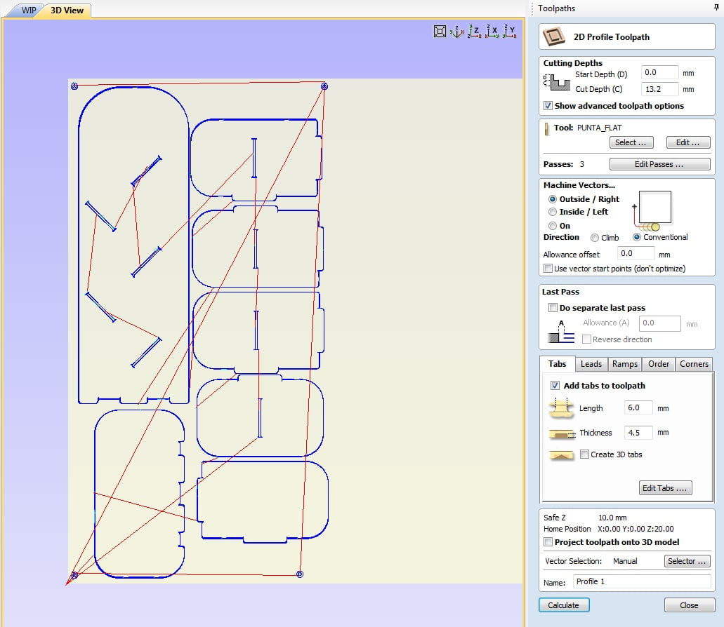
I then set the Machine Vectors as “Outside” and I proceeded adding tabs (stitches to ensure that everything stays put while working ) and ramps.
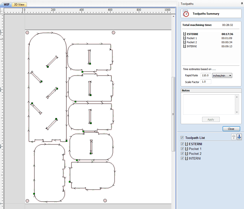
At the end, the software returned the processing timelines to me:
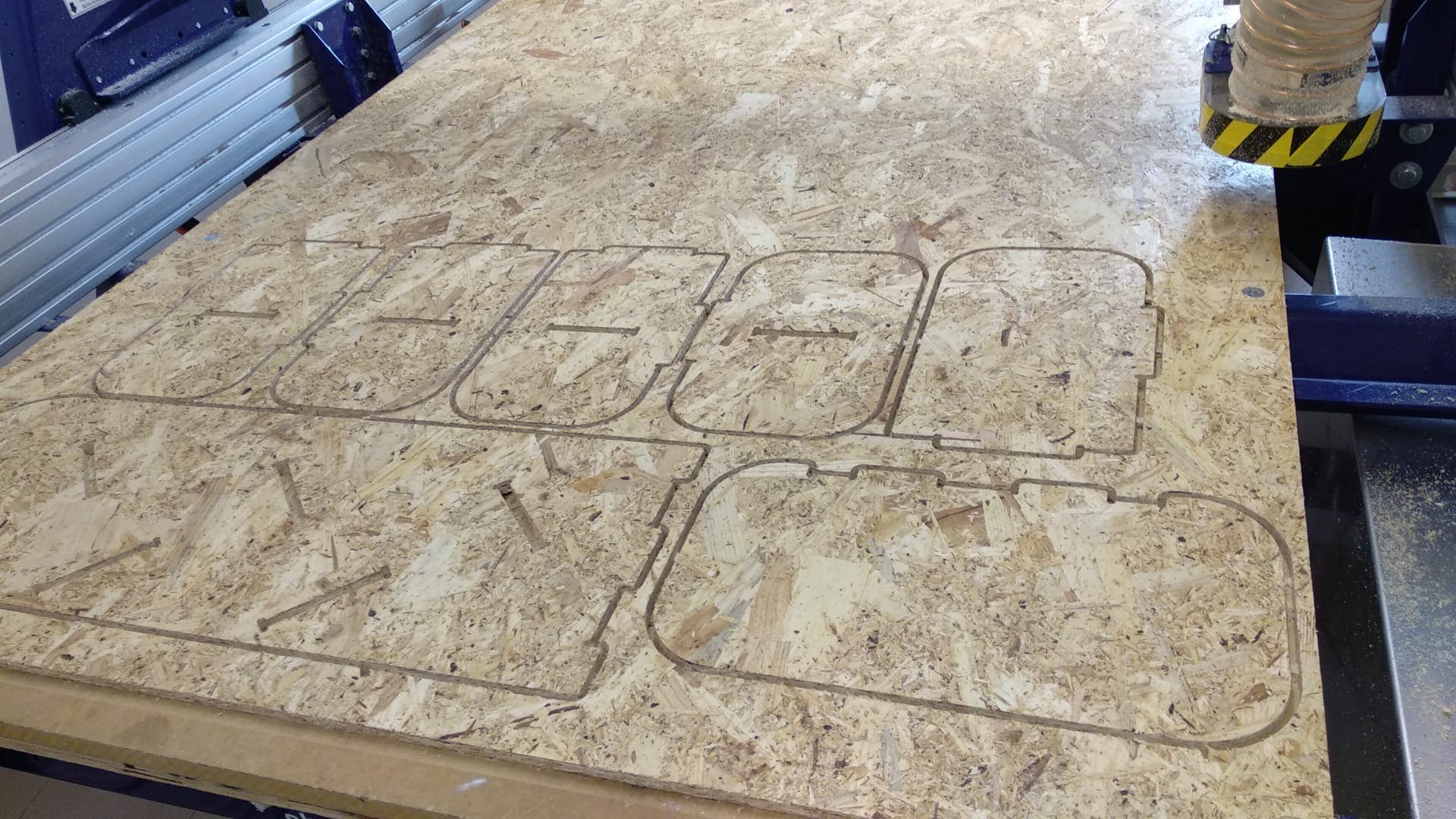
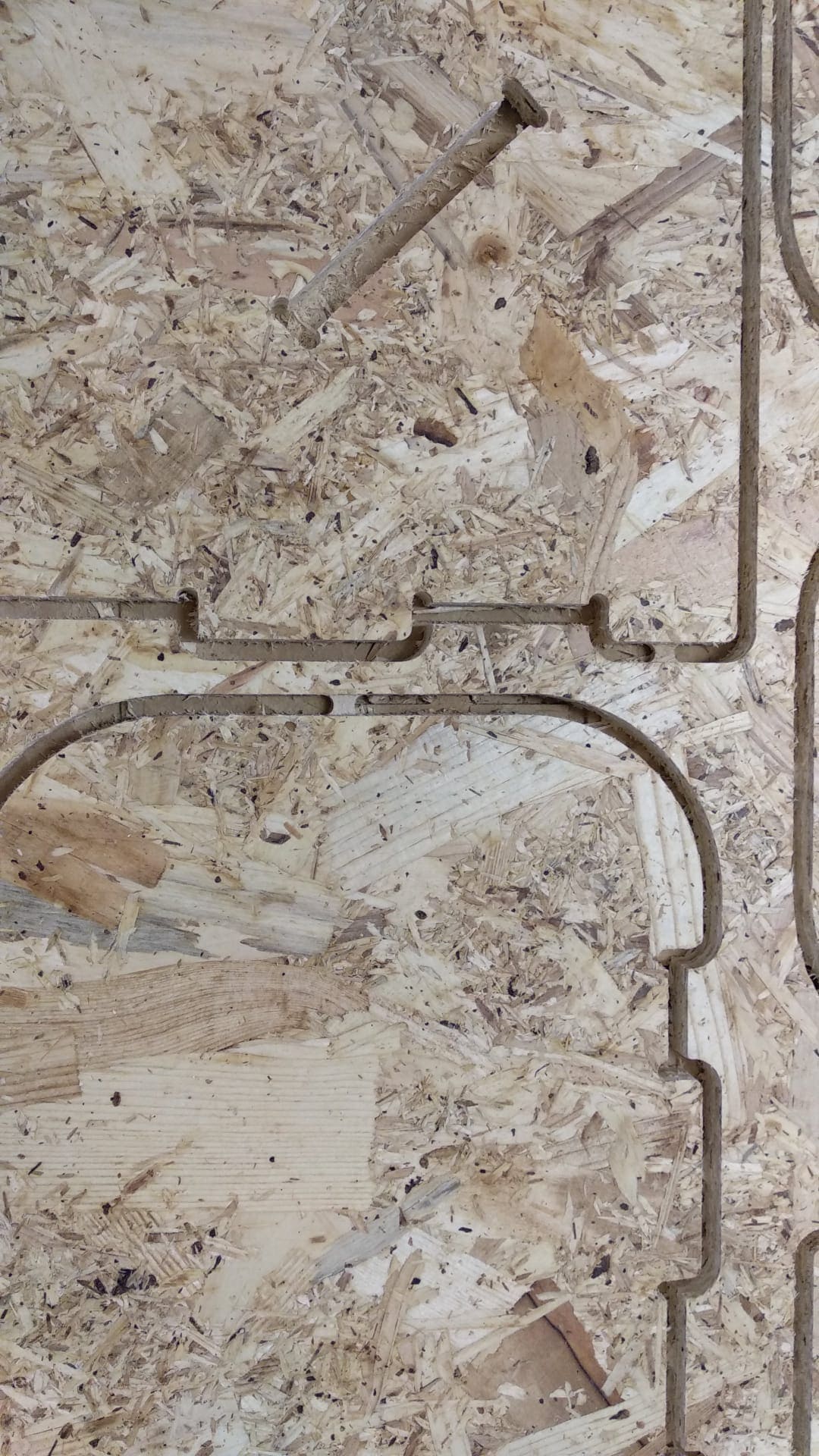
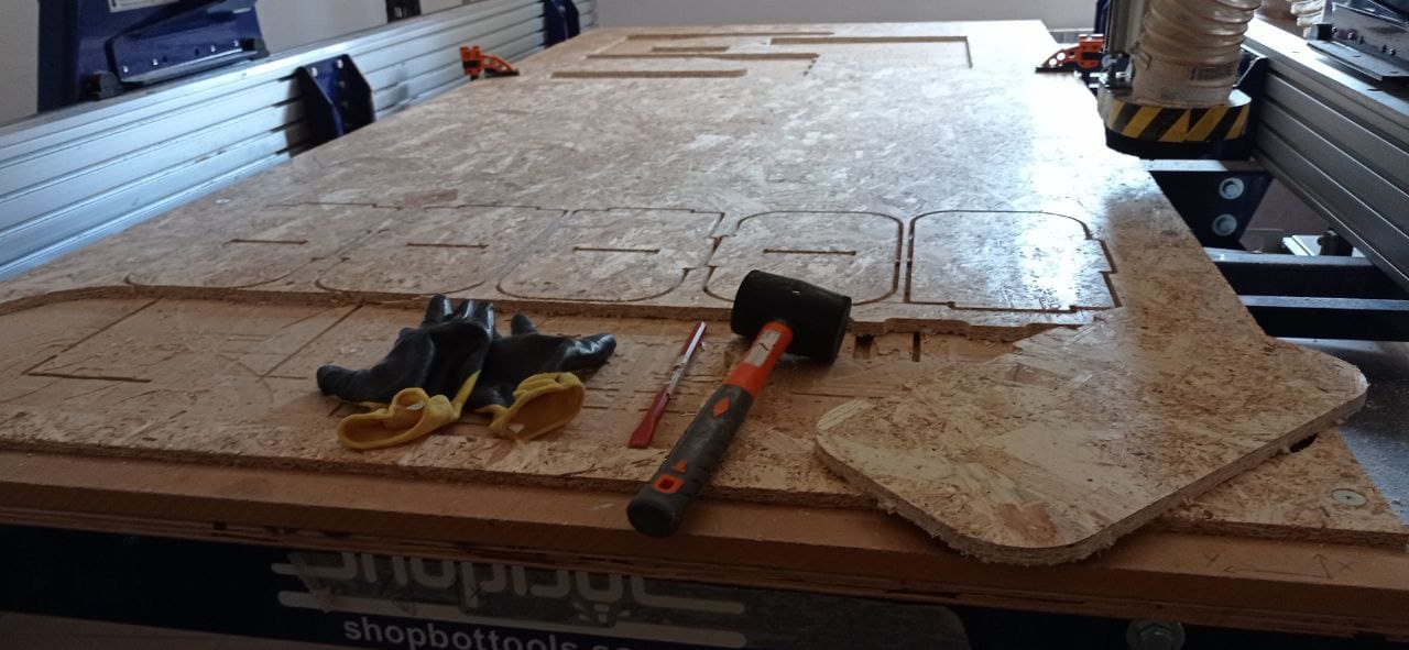
At this point, everything was ready and the big machine started its (noisy) work.
Final result:
ASSEMBLY
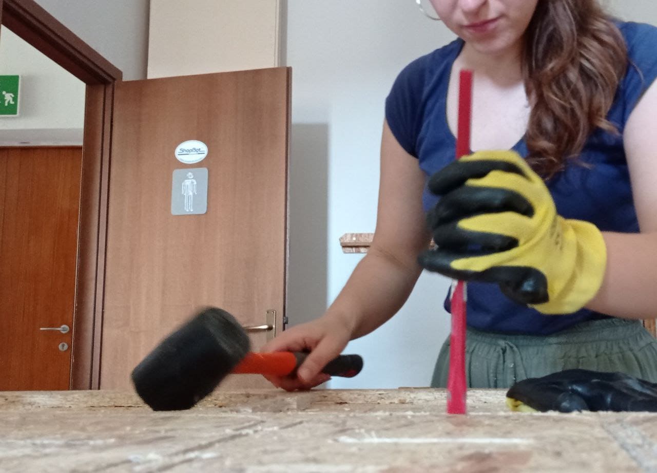
And so began the most fun part that turned out to be the most exhausting part ever!!!
I first removed all the tabs using a hammer and chisel. I then cleaned up each piece using sandpaper to make the edges smooth and even.
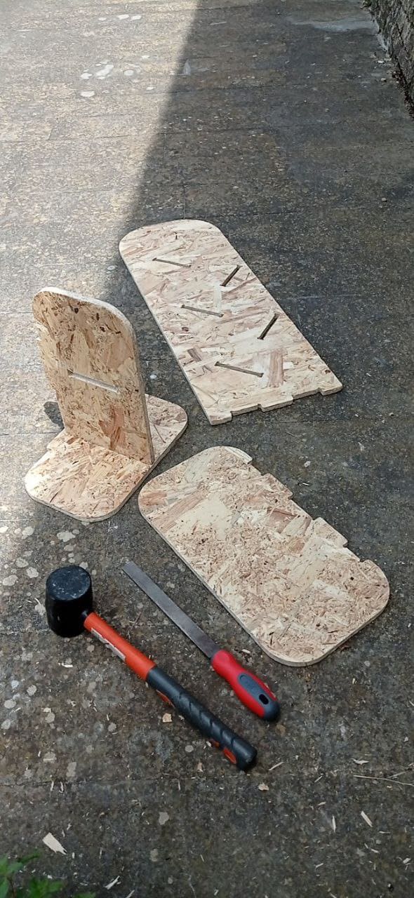
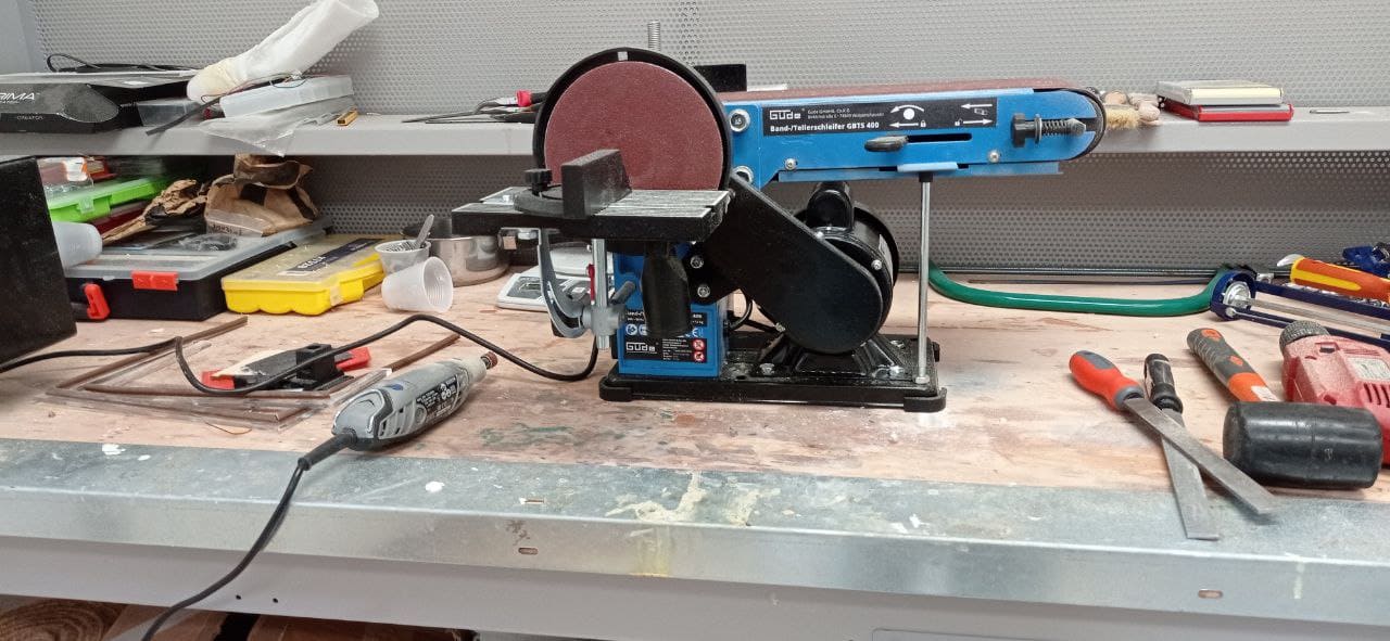
At the end of this phase began the actual assembly that took longer than expected because the teeth did not fit easily inside the pockets. I then had to use a grinder to slightly smooth the joints and after sweat and work everything ended for the best.
I therefore present to you my bookcase:
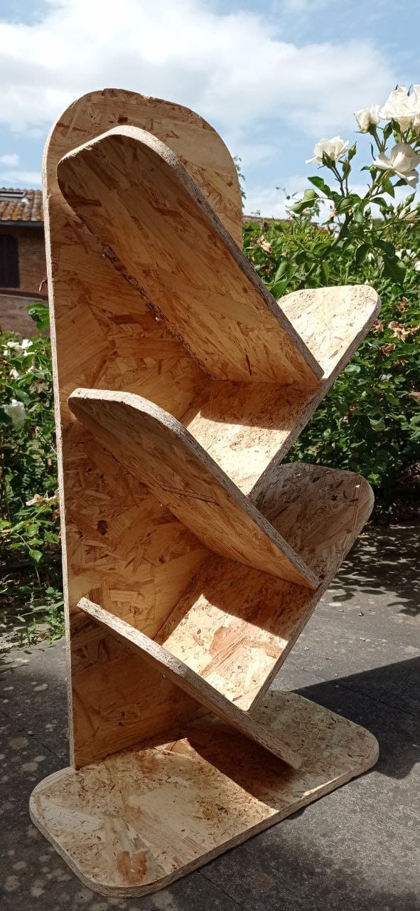
You can download the 3D model HERE
Group assignment
- Test runout, alignment, speeds, feeds, and toolpaths for your machine.
- Document your work (in a group or individually).
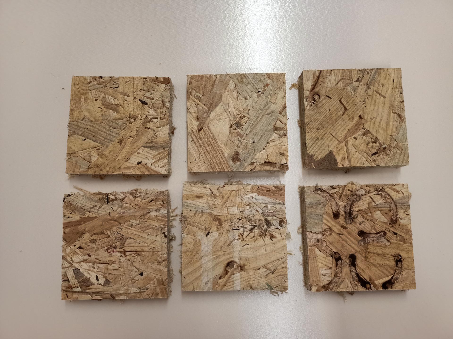
Feed rate and direction
The feed rate is the velocity at which the cutter is fed. We tried 3 different feed rate setting for our drill: 90 - 110 - 130. For the direction, there are two possible cut directions: climb and conventional We first drilled the board with one direction, then with the other one.
We decided that the best feed rate is around 100. We didn’t notice differences about the direction, this is correlated to the material that in our case was a OSB wood, but you can notice the difference using foam.
Stepover
Is the space between passes of a tool during an operation. We tried the difference between a 20%, a 50% and a 90% stepover. An higher stepover does not look as smooth as a low percentage stepover. We tried this time with the foam. Below you can see the results:
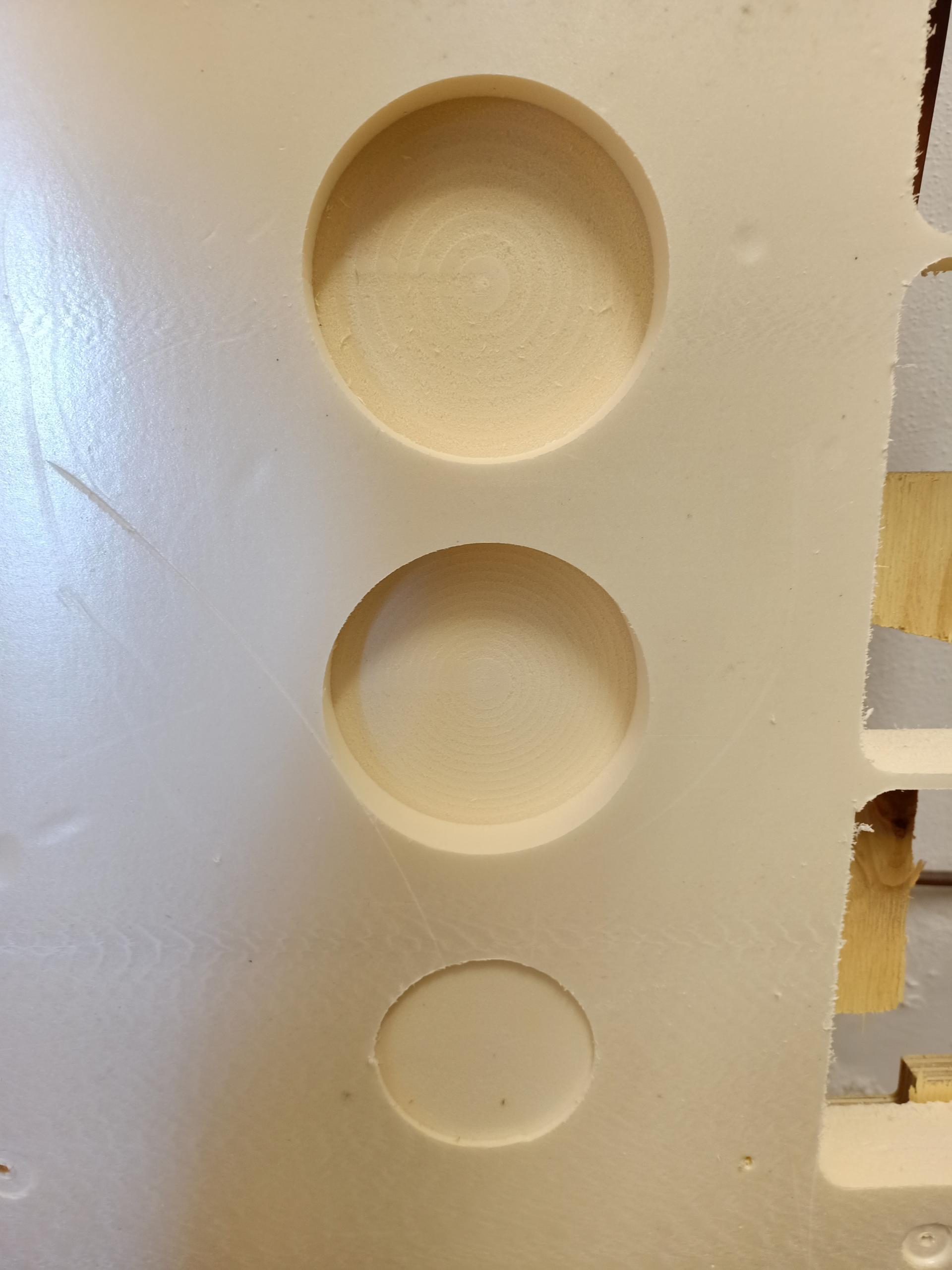
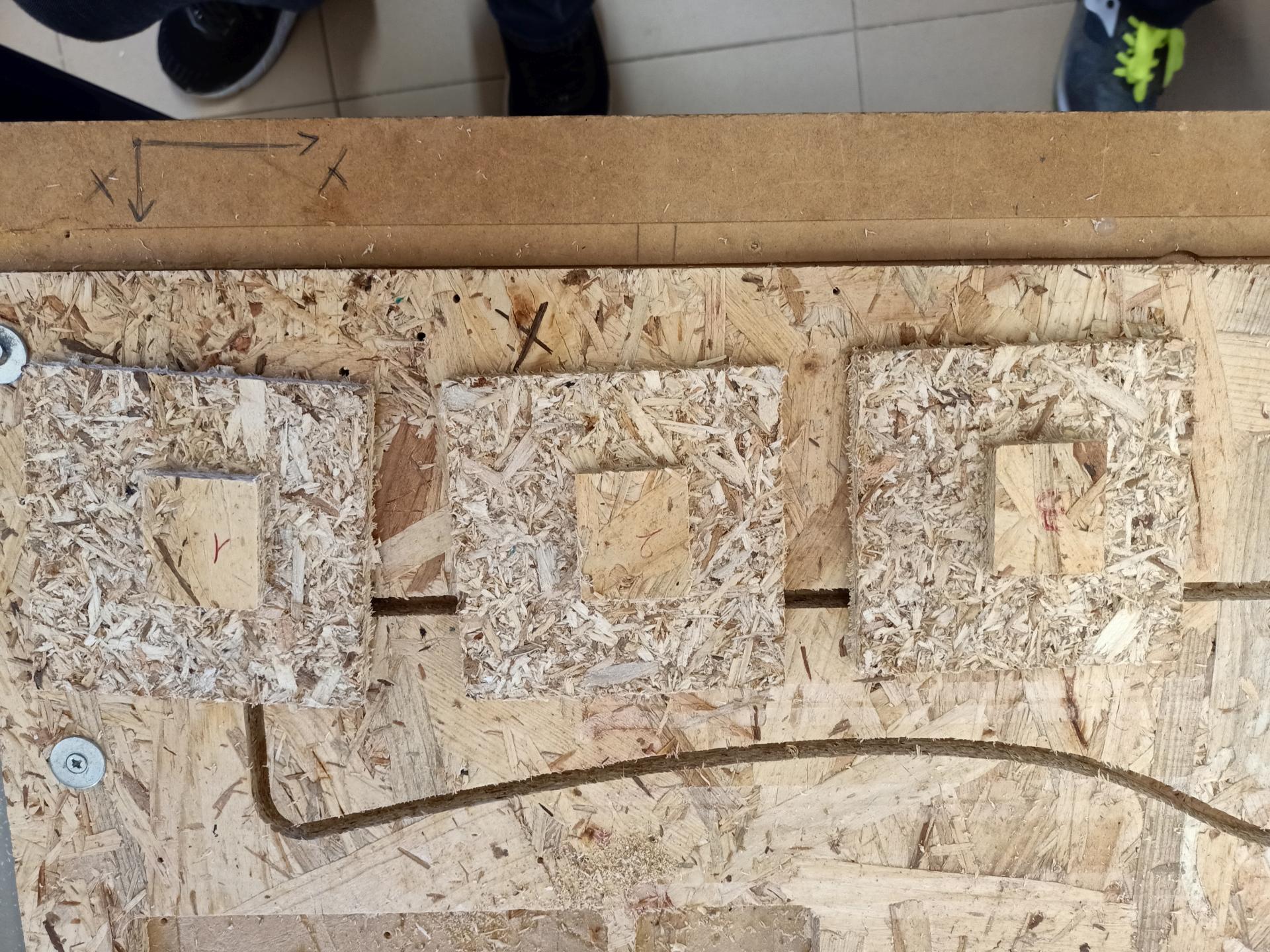
Pockets
A pocket is a type of toolpath that creates different depths inside an area. In the picture below you can see the pocket we create using different feed rate: