10. Input devices
Goal of the week:
- measure something: add a sensor to a microcontroller board that you have designed and read it
This week will be an unknown for me. I’m at my parents’ house, 400 km away from the lab, and all I have with me is a Super Starter Kit UNO R3 Project.
On the first day I opened it, looked at all the components inside and immediately closed it again. Everything was incomprehensible and unintelligible to me.
On the second day I got brave and unpacked all the elements of the kit. I decided that I should take an advanced step towards the enemy and establish a beginning of friendship for what will be a fairly long-lasting relationship.
The situation turned out to be this:
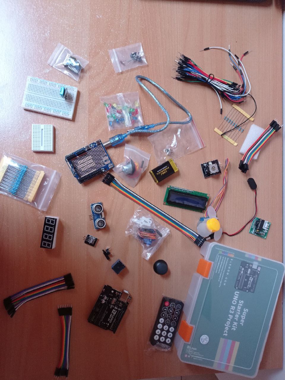
I’m certainly not known for my tidiness, but as always, in the midst of the mess and chaos I decided it could be fun. And so I started diving into tutorials and read every kind of web page that could make me understand what was in front of me.
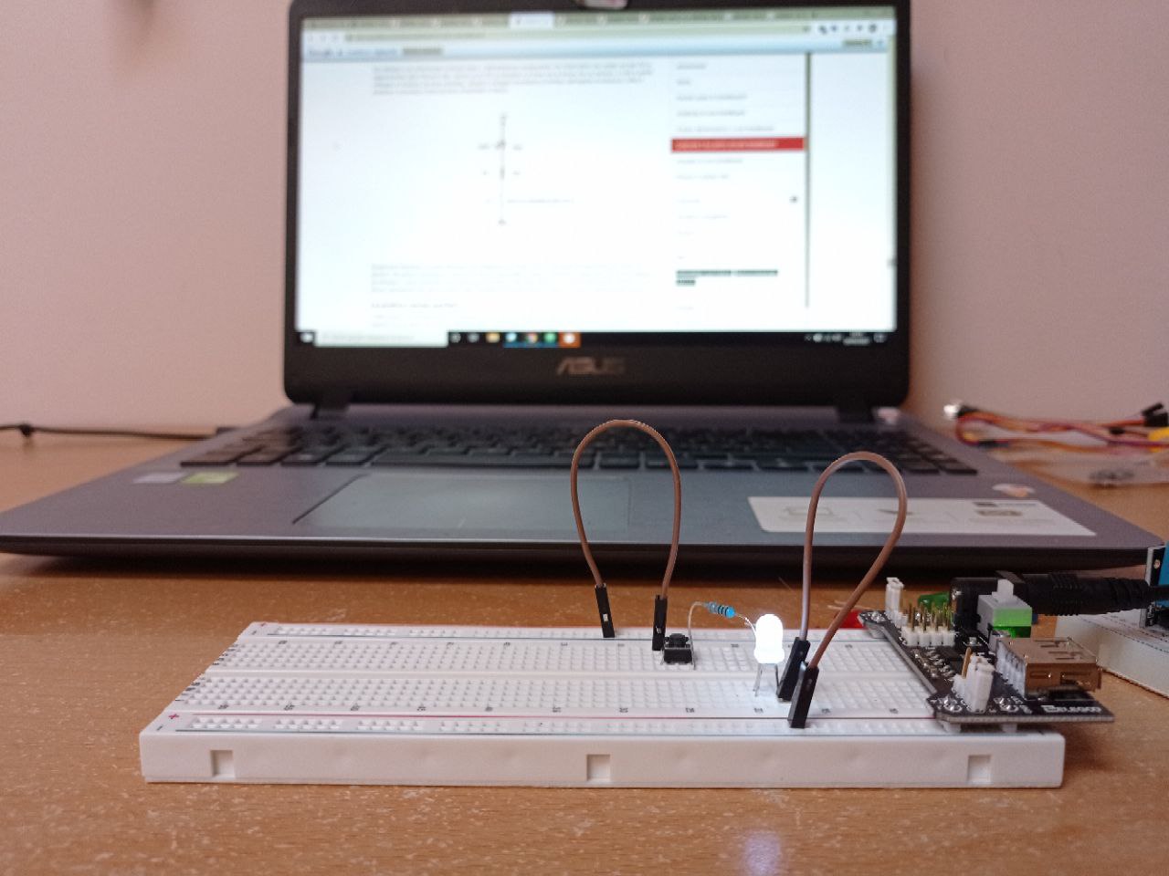
Immersed in one of Sparkfun’s BreadBoard tutorials (yes, I finally understood why they are called that way and it amused me quite a bit!) there was a little schematic I could reproduce on my breadboard… and so I incredibly managed to switch my first led with my Arduino’s kit!
After the unexpected success, I decided that this could really become fun. So I dived back into my tutorials, looking for something new!
What is an INPUT DEVICE?
We are using Microcontroller to interact with the real world. For this interaction we can use two types of components: input and output. An input device allows us to take information from the real world, an output device operates on the real world. An input can be digital or analogue. A digital input has only two logical states: 0 (0V) and 1 (5V), so it proceeds in discrete steps and comprises a specific number of steps. An analogue input has an infinite number of steps and values. The example that best enables us to understand this difference is to think of a digital clock and an analogue clock and to think of the information they give us. The analogue allows us to obtain information with extreme precision. From the microcontroller, the analogue signals are managed with the Analog to Digital Converter, which allows us to measure the voltage in much smaller steps. In the arduino, the analogue pins are grouped in the bottom right-hand corner and go from A0 to A5.
ANALOG TO DIGITAL CONVERTER
To understand better the Analog to Digital Converter (ADC), I used this tutorial.
We often need to measure signals that vary, these are called analog signals. All microcontrollers have a device built into them that allows us to convert these voltages into values that we can use in a program to make a decision.
“An Analog to Digital Converter (ADC) is a very useful feature that converts an analog voltage on a pin to a digital number. By converting from the analog world to the digital world, we can begin to use electronics to interface to the analog world around us.”
On the Arduino board, the pins that can read analog voltages have an ‘A’ in front of their label (A0 through A5). The ADC on the Arduino is a 10-bit ADC meaning it has the ability to detect 1,024 (2^10) discrete analog levels. The input range can be changed using analogReference()
VOLTAGE DIVIDER
Another important concept I need to learn for this week was the Voltage Divider, a simple circuit which turns a large voltage into a smaller one. A voltage divider involves applying a voltage source across a series of two resistors. Voltage dividers have tons of applications, they are among the most common of circuits electrical engineers use. A potentiometer is a variable resistor which can be used to create an adjustable voltage divider.
Basically, we can use an analog input that will converts a voltage level into a digital value that can be stored and processed in a computer. But why would you want to measure voltages? There are a multitude of sensors available which convert things like temperature, pressure, etc. into voltages. The voltages can then be easily measured by various kinds of hardware, and then read into a computer. The computer can then convert the voltage value into it’s original type (temperature, pressure, etc) and the value can then be stored in a file or used to control something else outside of the computer.
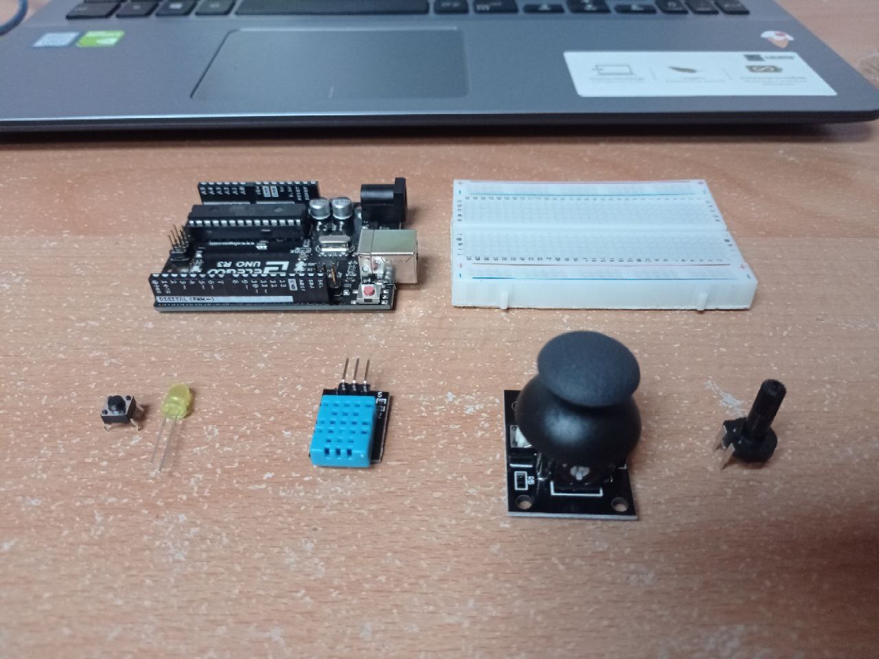
So I decided to try with different input device: button, Temperature and humidity sensor, joystick and a trimmer.
BUTTON
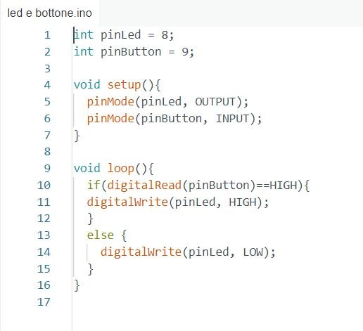
Switches are very simple components. When you press a button two contacts are connected, so that electricity can flow through them. In reality there are only two electrical connections. Inside the switch the pins are connected in pairs. My first real attempt with Arduino was recreate the code for turning on the led by adding a button and a pull down resistor capable of bringing the current to zero to ensure I always know the status.
This was the code I wrote:
And this was the result:
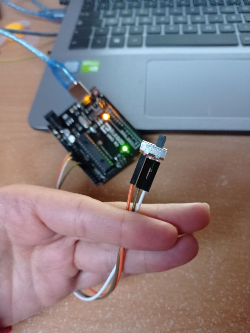
SWITCH
My instructor give me another component that was not included in the kit: a switch. It’s a button but the way of use it is completely different. So I read on Internet some theory about it. From a technical perspective, slide potentiometers are just slide knobs that adjust a potentiometer by changing the knobs position. Then, the potentiometer changes a voltage level of the signal that is bound to an output pin. This signal can be used by the analog-to-digital converters of an Arduino (=analog pins) to use the position in an Arduino program.
The goal is to retrieve the slide knob position and to print it out on the serial monitor of the Arduino IDE.
An output of the slide pot has three pins: GND, VCC and DTB. GND is connected with ground. VCC is connected to the voltage signal. The signal pin DTB has a voltage level that corresponds to the slider knob position and depends on the voltage level of VCC. For example, if VCC has 5V, the voltage levels look like this:
- DTB = 0V on the most outer left position
- DTB = 5V on the most outer right position
So, the most outer right position is always equal to the voltage level of VCC. The Arduino’s analog pins are able to read voltage levels up to 5V by a so-called analog-to-digital converter. As a result, the analog value will be available as digital values in the Arduino program. The digital values range from 0 (for 0V at analog pin) to 1023 (for 5V at analog pin).
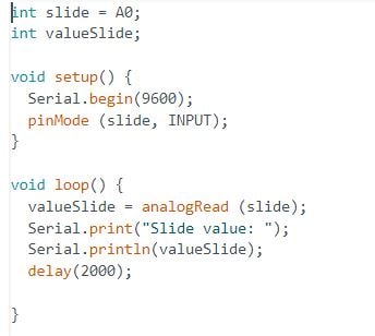
I then copy the code for my switch:
TEMPERATURE AND HUMIDITY SENSOR
Thermistors are variable resistors that change their resistance with temperature. In my box I had a DHT11 temperature and humidity module. It’s accurate enough for most projects that need to keep track of humidity and temperature readings. I’ll be using a Library specifically designed for these sensors that will make my code short and easy to write. The aesthetic appearance is that of a light blue perforated box. The information it releases is quite precise and combines humidity and temperature using a single-wire serial port, so it transmits and receives data on the same wire.
The DHT11 temperature and humidity sensor is a composite sensor that outputs calibrated digital temperature and humidity signals. This digital module contains technology that ensures excellent reliability and stability over a long period of time. The sensor includes a resistive humidity sensor and an NTC temperature measurement device, both connected to a high performance 8-bit microcontroller. The connections are 5V, GND and signal. The latter can be connected to any pin on our UNO board.
The following is the code that I copied from this (tutorial)[https://www.youtube.com/watch?v=30w4nFH62jM]:
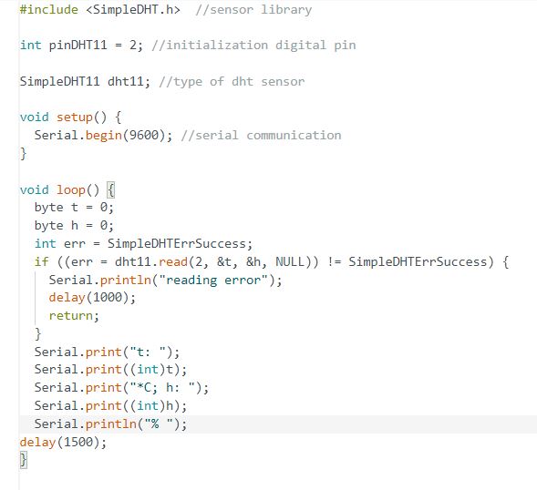
And this was the result:
JOYSTICK
The Analog Joystick is similar to two potentiometers connected together, one for the vertical movement (Y-axis) and other for the horizontal movement (X-axis). The joystick also comes with a Select switch. If the stick is moved on X axis from one end to the other, the X values will change from 0 to 1023 and similar thing happens when moved along the Y axis.This joystick also contains a switch which activates when you push down on the cap. The basic idea of a joystick is to translate the stick’s position on two axes — the X-axis (left to right) and the Y-axis (up and down) into electronic information an Arduino can process. When the joystick stays in its center position the value is around 512. In order to read the joystick’s physical position, we need to measure the change in resistance of a potentiometer. This change can be read by an Arduino analog pin using ADC.
The joystick is connected to two analogue pins to read X (A0) and Y data (A1) and a third analogue pin will be used to read joystick pressures (it can also be left unconnected, but in my case it’s connected to a digital pin). To receive stable readings from the KEY/Select pin, it is necessary to connect the VCC voltage via a pull-up resistor. The Arduino board’s internal resistor in the digital pins can be used for this purpose.
Basically, we need 5 connections to the joystick. The connections are: Key, Y, X, Voltage and Ground. Y and X are analogue while Key is digital. If you don’t need to use the joystick pressure you can simply not use it and just use the other 4 pins.
This is the code:
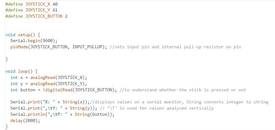
And this is the result:
POTENTIOMETER
A potentiometer is a simple knob that provides a variable resistance, which we can read into the Arduino board as an analog value. I connected three wires: ground, 5 volts and the third from analog input 2 to the middle pin of the potentiometer.
By turning the shaft of the potentiometer, we change the amount of resistence on either side of the wiper which is connected to the center pin of the potentiometer. This changes the relative “closeness” of that pin to 5 volts and ground, giving us a different analog input. When the shaft is turned all the way in one direction, there are 0 volts going to the pin, and we read 0. When the shaft is turned all the way in the other direction, there are 5 volts going to the pin and we read 1023. In between, analogRead() returns a number between 0 and 1023 that is proportional to the amount of voltage being applied to the pin. To make the circuit a little more complex, I added a LED and set 3 ranges of values according to which the LED could be off, blinked or off.
This is the code:
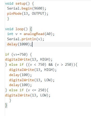
And this is the result:
DESIGN THE BOARD
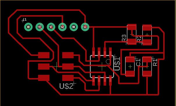
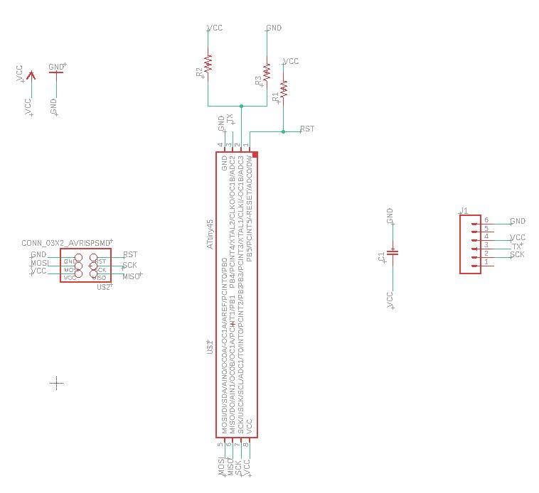
The next step was design with Eagle the board with the NTC THERMISTOR
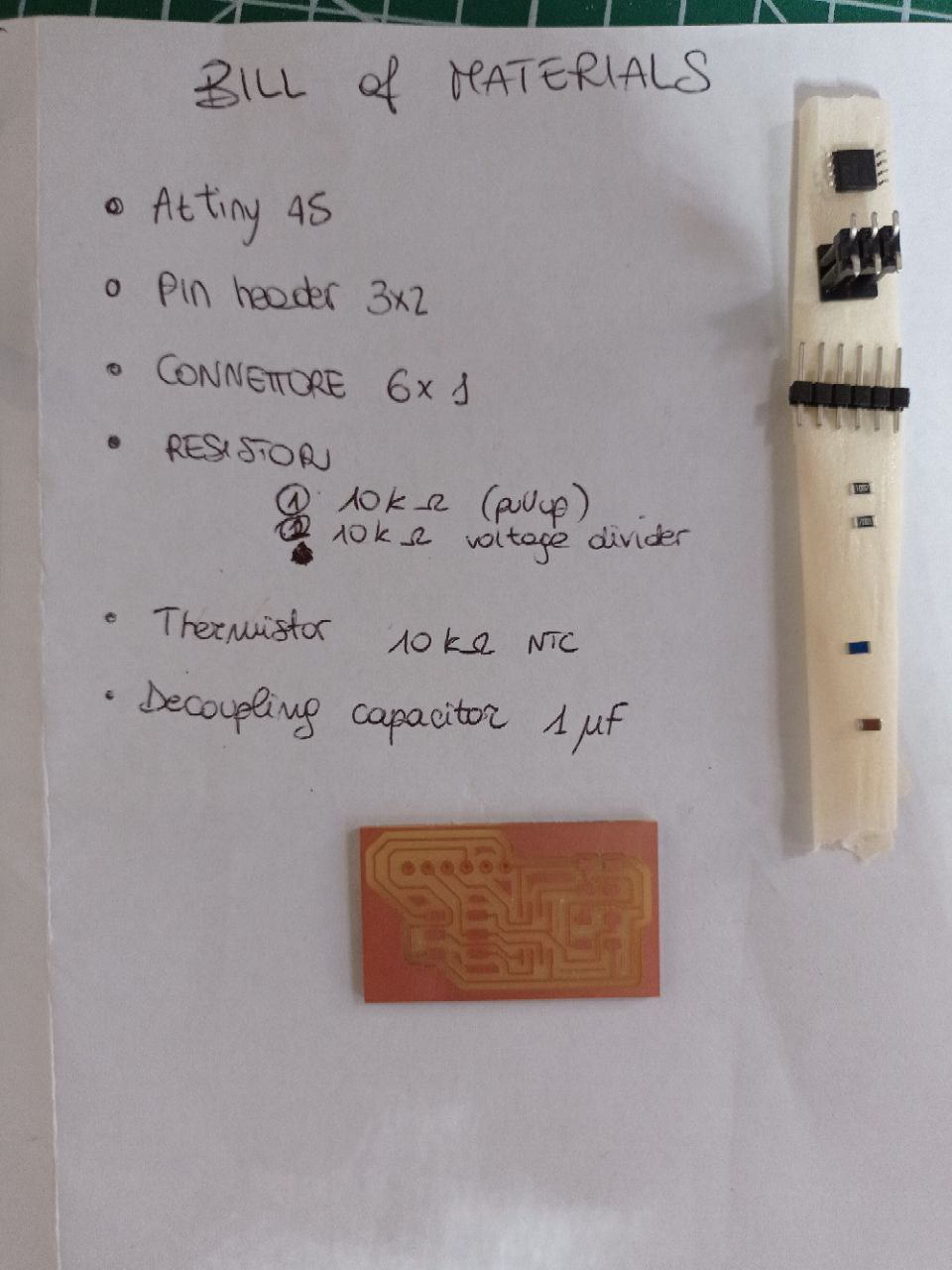
I decided to use an ATtiny45 and I did a simple voltage divider with a 10kOhm resistor. The other components used were: + Pull-up 10k resistor + Decoupling capacitor (1 uF) + AVR ISP 3x2 + FTDI (1x6)
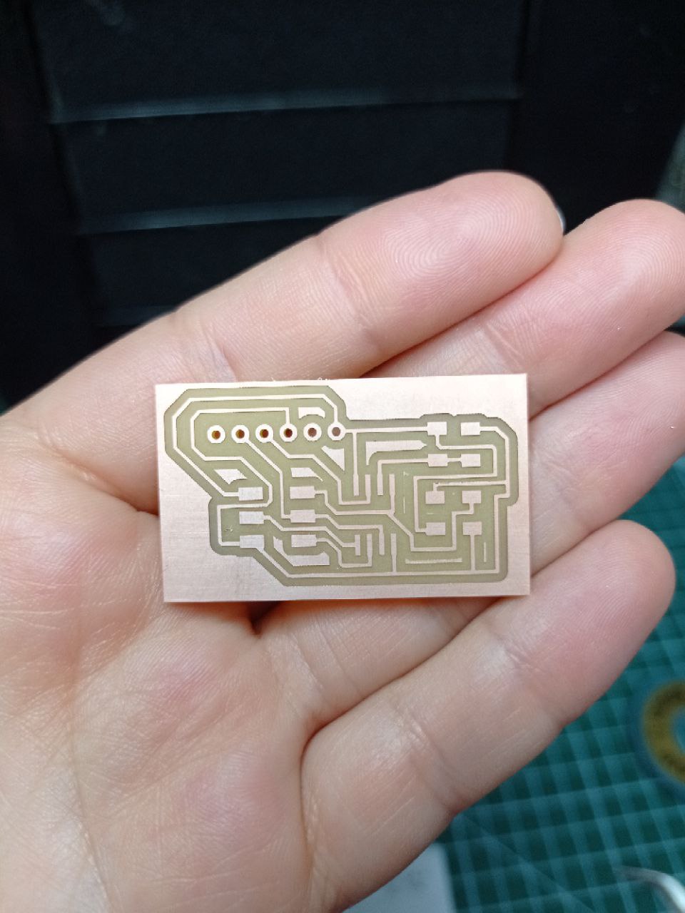
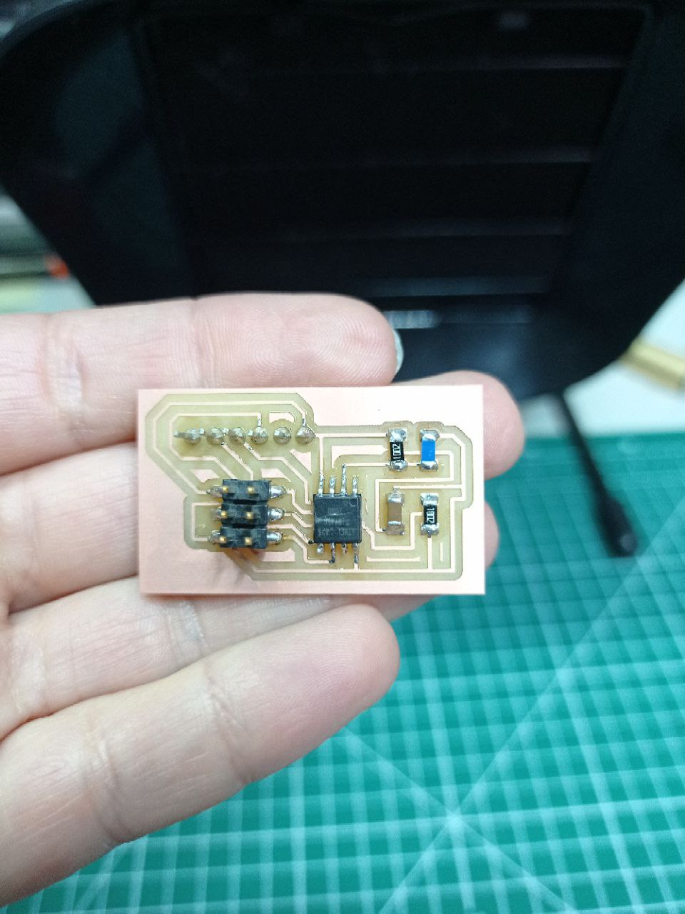
MILLING AND SOLDERING
I milling the board, prepared my Bill of materials and soldered my PCB.
For programming the sensors, check out the final project page, section “programming”, where I used the dth sensor to control the temperature of my BiOven.