5. 3D scanning and printing
Goals of the week:
- Group Assignment: test the design rules for your 3D printer
- Design and 3D print an object that could not be made subtractively
- 3D scan an object
This week has been quite exciting for me. The techniques and theories about the 3D printer were nothing new. Last year, in a university course about physical computing we studied 3D modelling, but being in the middle of the pandemic, we didn’t get to see live how the machine worked. So it was very interesting to be able to finally see everything up close.
So, this time, I brushed up on some of the techniques I remembered and as the first part of this week’s work, we went on a group assignment and printed out models to test the machine. In the lab we have an Ultimaker 2.
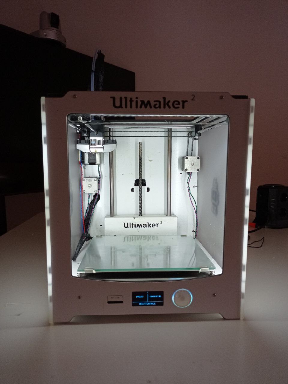
Our instructor of the week, Flavio, explained us how to use the machine and how to use Cura, a software that allow you to decide all the settings for the print and transform the stl model in a gcode. A gcode is a text file in which you enter the coordinates that the machine must follow to recreate the model. So, we learned how to set Cura and how to use physically the machine (how to change the coil, how to clean the plate, how to control prints).
GROUP ASSIGNMENT
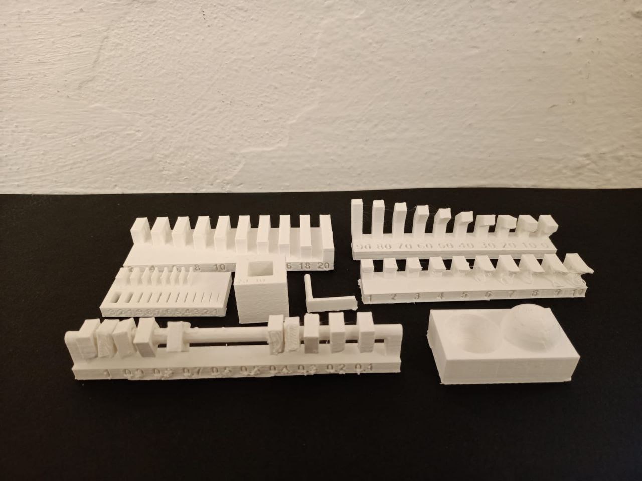
The group assignment helps us to understand the basic of our machine, the design rules and the different settings. With the group assignment we also realised how important it is to organise the press’s printing schedule. It took us a total of two days to print all the models. For the smaller ones, the machine took an average of around twenty minutes between heating and cooling and printing. The larger and more complex models took up to an hour.
If you want to know more about our work, visit our lab site!
SCAN THE OBJECT
The second goal of the week was to 3D scan an object. I have had several experiences with photogrammetry in the past, always for the physical computing course. I found it a frustrating experience, not so much because of the software as because of the many attempts to find the right object and to take pictures in a suitable environment and with a good camera. The pandemic and lockdown in this case certainly didn’t help. But this time I gave photogrammetry another chance!
Our instructor advised us to look for objects that were not transparent, shiny, metallic, too regular or black. To use a focal lens between 50-70 and to pay attention to the ISO values. To use the RAW format for the photos but to process them with special software such as Photoshop to transform them into TIFF format and make them lighter and easier to process by the 3D model software.
Other recommendations were to choose the location carefully, taking care not to leave any shadows on the object. The ideal condition would be a cloudy day where there is no direct light. Other recommendations were to raise the object in such a way as to be able to photograph it even in the most difficult parts (usually the lower part). To position the object in such a way as to be able to rotate around it at 360° trying to maintain the same distance and not use the zoom.
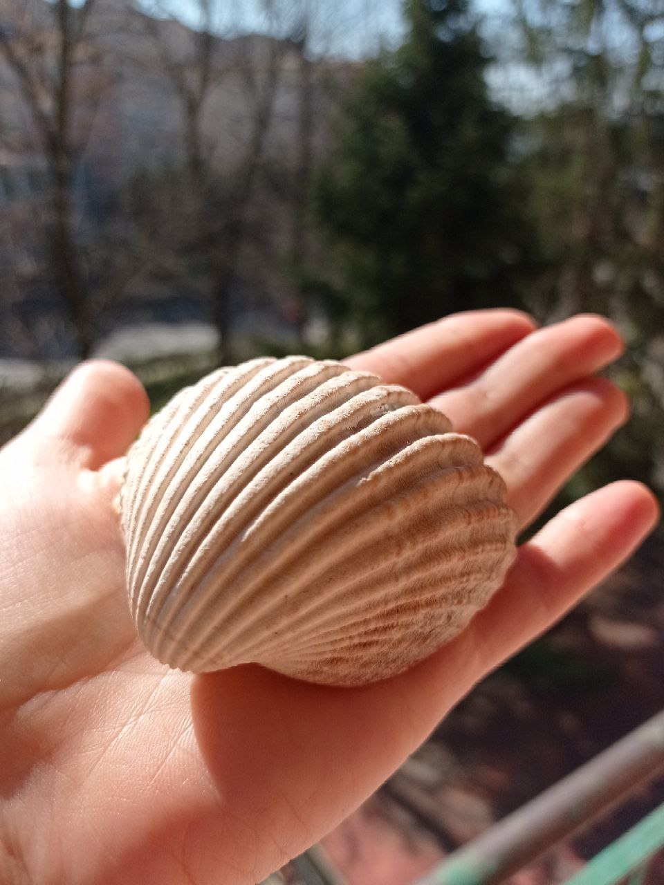
After the various recommendations, I then started to think about the object and the best choice (also in relation to the traumatic experience of the past) was to use a shell I picked up on the way to Santiago, arrived at the ocean. So, maybe was the Santiago spirit and the energy of my shell, but IT WORKS AT THE FIRST ATTEMPT!
For the photos I decided to use my phone’s camera and set the recommended values, so that I don’t have too heavy images and don’t have to convert them.
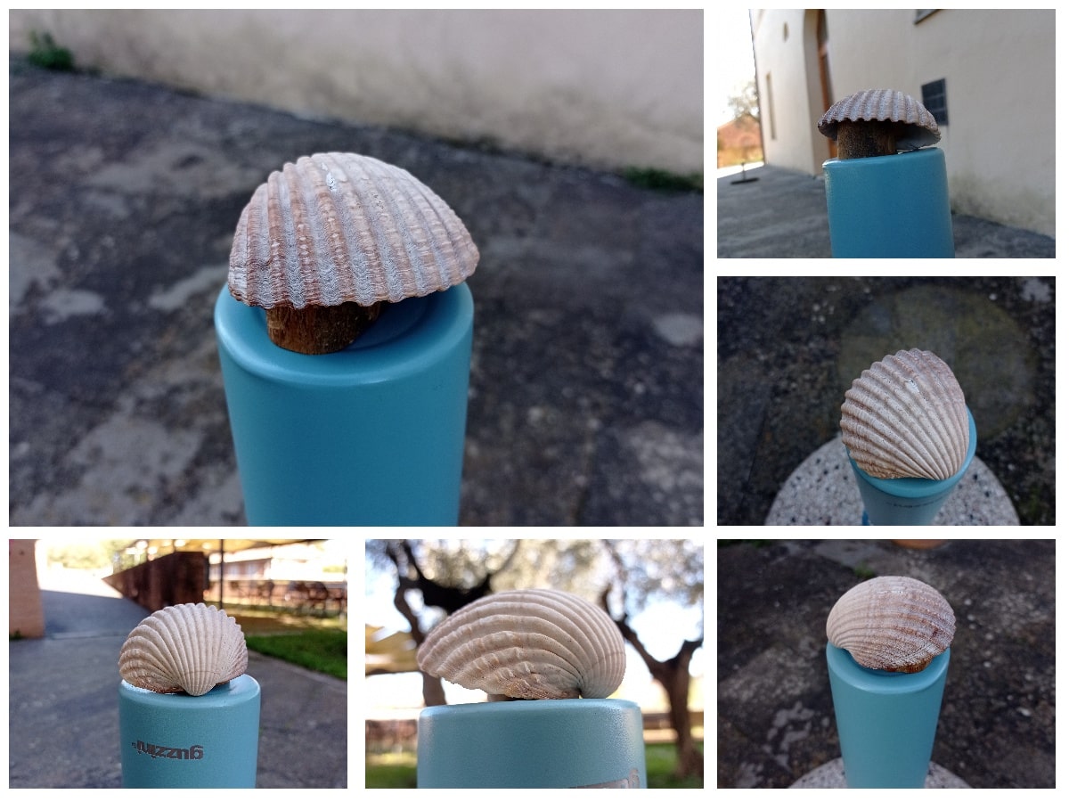
As a setting I chose the garden outside the lab. It was a clear sunny day without the shadow of a cloud (my metereopathy was very happy, my expectations for photogrammetry a little less so!), but I chose to position myself in a shady spot, using a circular elevation that allowed me to walk around the object without any problems. I used my water bottle and a small wooden support to raise the shell a little and make it easier to take pictures. I took about 80 photos by positioning myself either at 45° to the object, or in front of the object and then shooting the details up and down.
MODELLING THE OBJECT
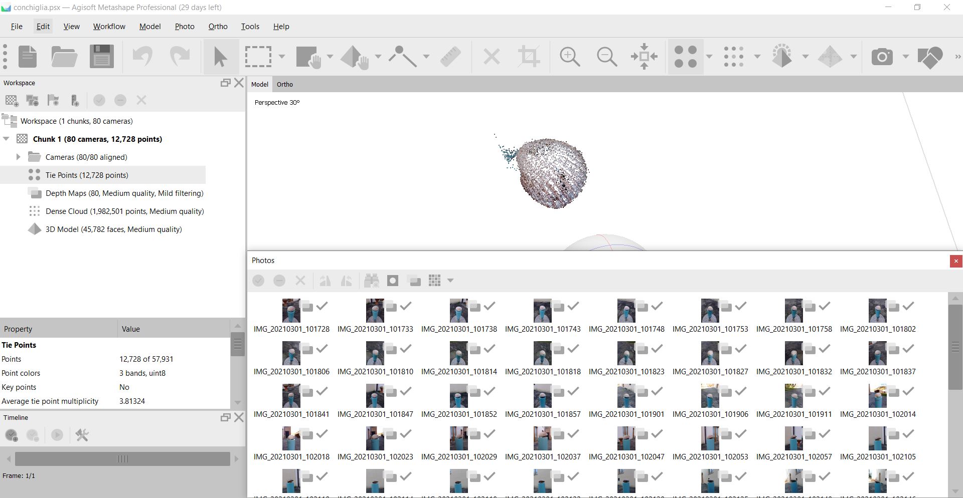
After that, I opened Agisoft Metashape Professional (using the free trial period). It’s a software product that performs photogrammetric processing of digital images and generates 3D spatial data. I used Metashape in the past so I remembered the commands. First I add the photos, then clicked on process –> align and I cross my finger! At this stage Metashape searches for common points on photographs and matches them, as well as it finds the position of the camera for each picture and refines camera calibration parameters. As a result a sparse point cloud and a set of camera positions are formed. Fortunately (and almost unexpectedly) the program managed to align 80/80 photos. I deleted all the excess points that represented the external environment and not the shell so as to begin the process of cleaning the model.
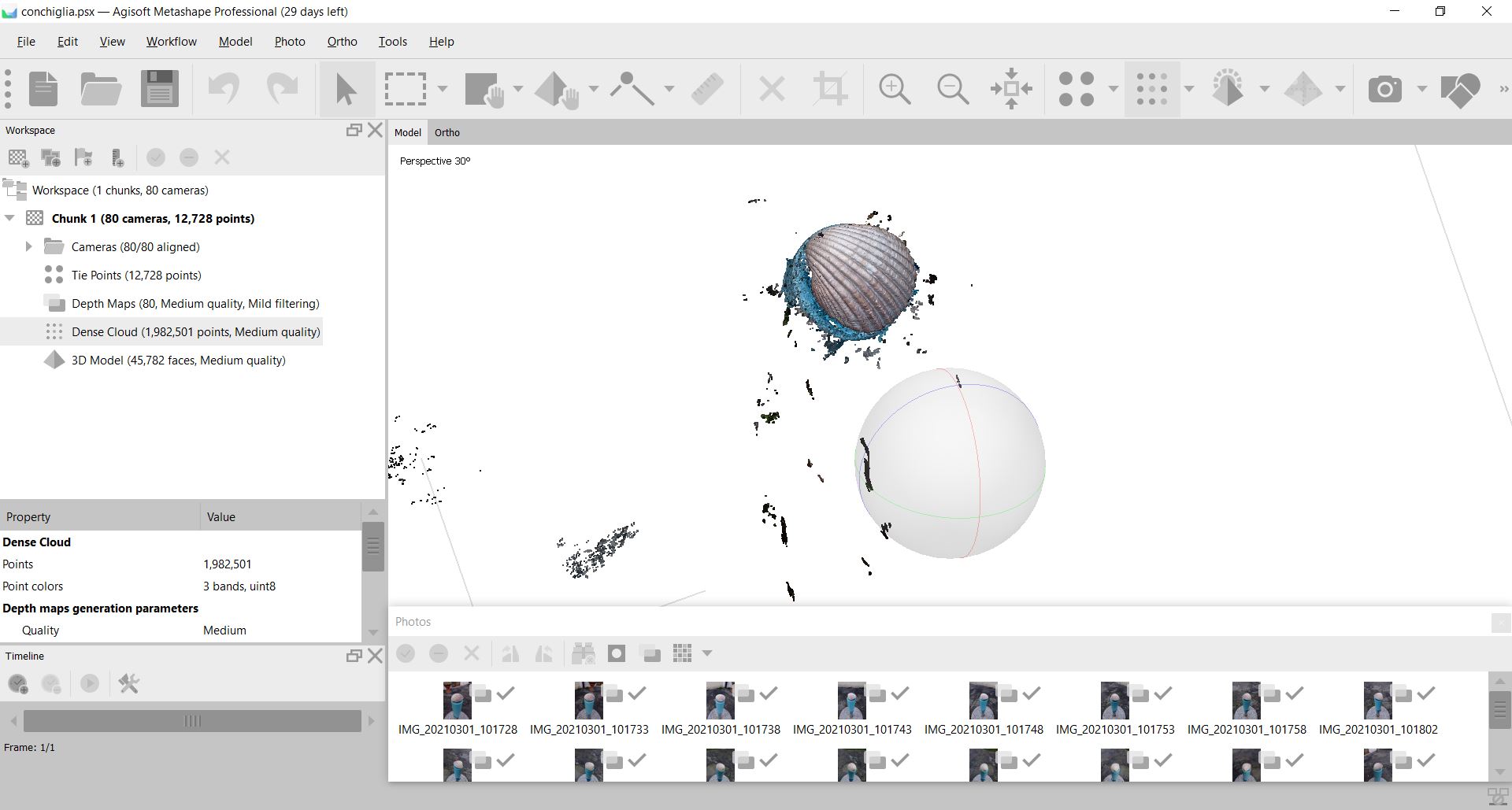
The next stage is generating dense point cloud, based on the estimated camera positions the program calculates depth information for each camera to be combined into a single dense point cloud.
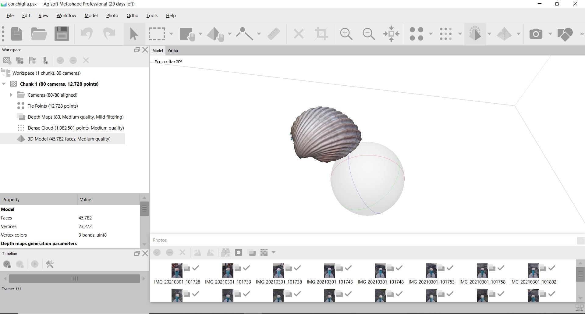
The last step was building mesh. Based on the point cloud information Metashape reconstruct polygonal model - mesh. It took few minutes but the final results was this:
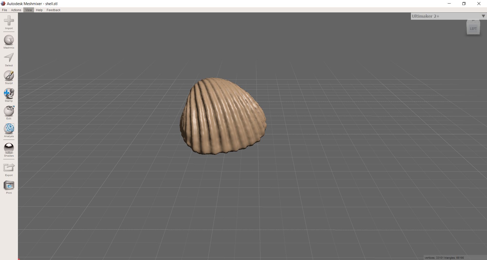
I exported the stl model and I saved the metashape format in case I had to change something in the model itself. Then I opened the stl file with Meshmixer a free software that allow us to work on the mesh of our model. I was very proud of my shell but when I opened it with meshmixer I noticed that there were several imperfections.
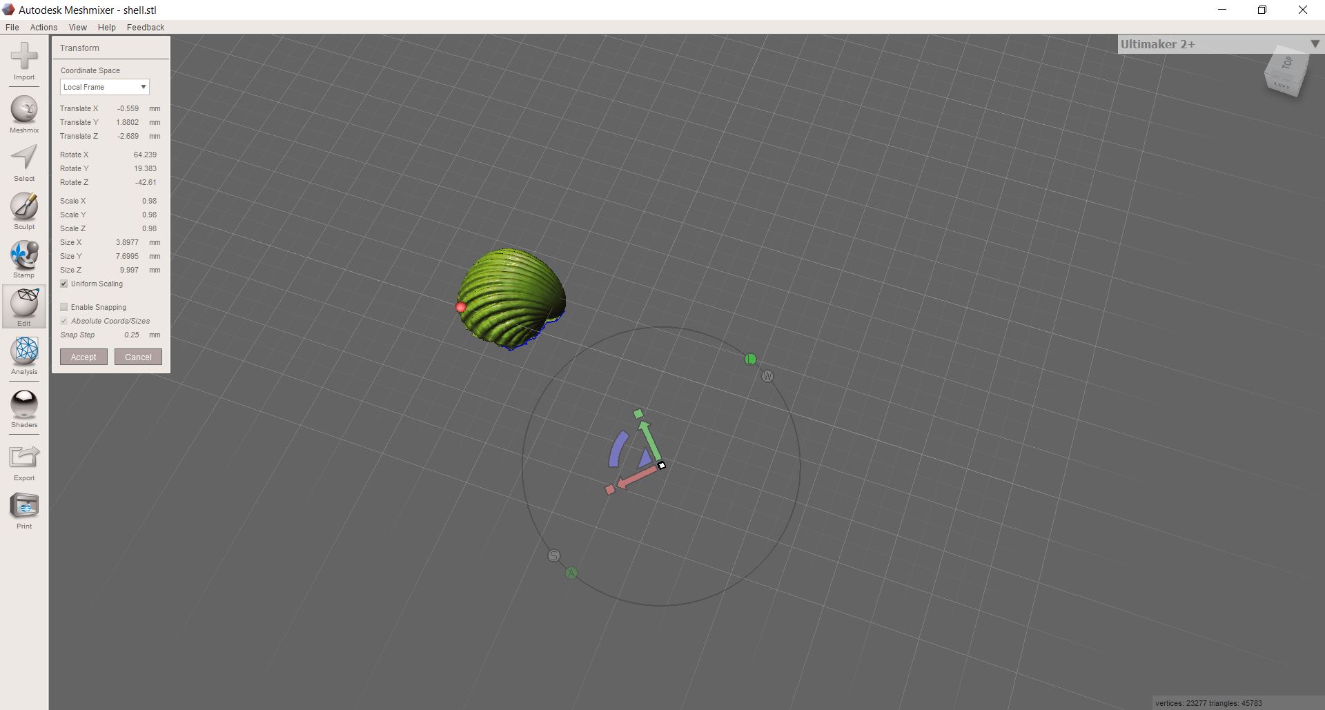
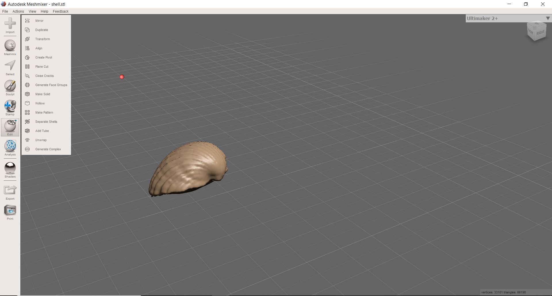
So I started working on it, especially on the lower part, which the photogrammetry had not been able to process completely. Using the inspection command I was able to fix the most damaged parts of the model and close the bottom part. Since it was very irregular and disconnected, I worked on it with different brushes in order to obtain a more homogeneous surface. After the final processing, the resulting model looks like this:
PRINT AN OBJECT
The last goal of the week was to print an object that could not be obtained by subtractive techniques.
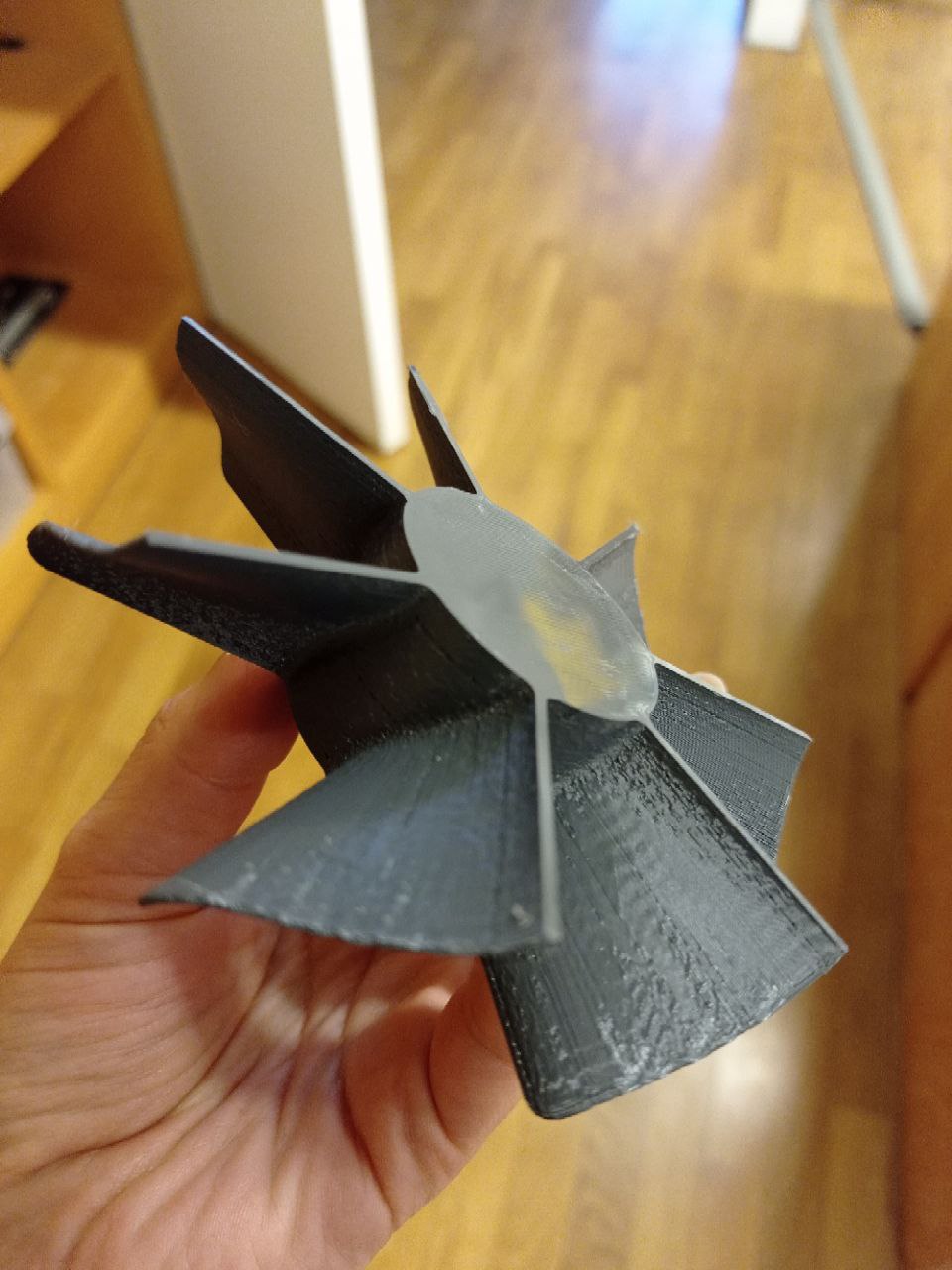
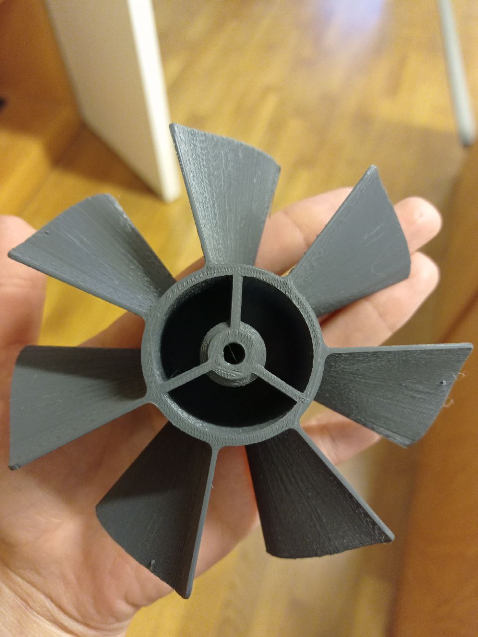
I therefore decided to use the model of the fan, which could be part of my final project, because the blades attached to the cylinder are oblique and rounded and this would have made it impossible to print this model subtractively using a milling cutter. Since the shape is complex, it had to be printed with the 3D printer. The size of the object from the end of one blade to the other is about 9 cm.
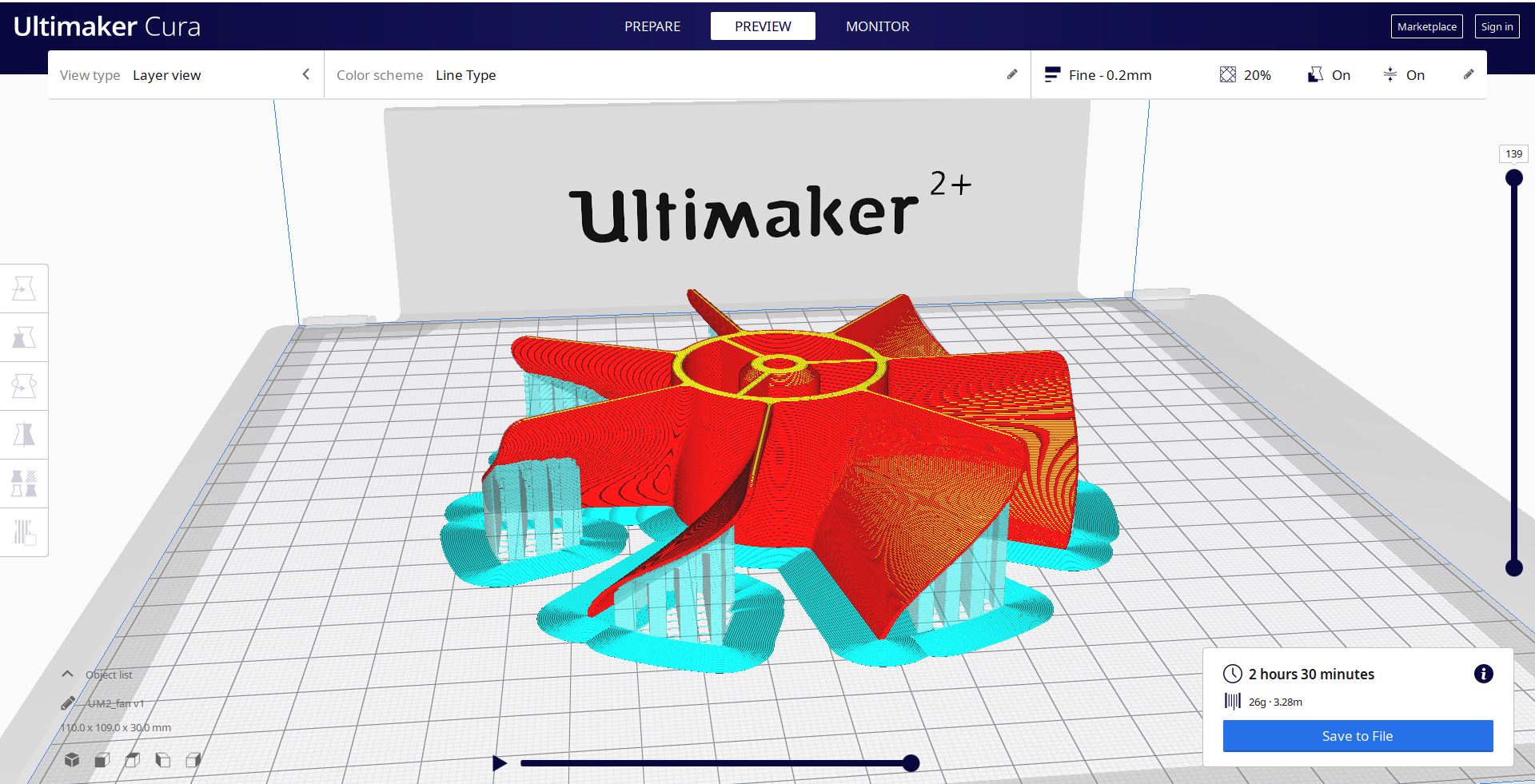
So I imported the stl from Cura and started setting the variables.
First of all I turned the model so that the hollow part was facing upwards and therefore the first layer was more stable as it was a homogeneous surface.
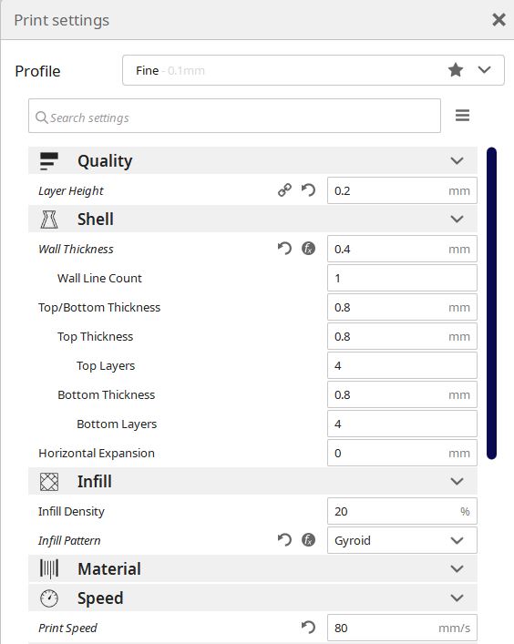
I then set the layer height, the thickness of the single layer, to 0.2 mm. I chose this value because the model did not need extreme precision and detail and so I could have reduced printing times in this case.
For the wall thickness, the thickness of the outer shell, I chose 0.4, which is the diameter of the auger of our 3D printer.
For the infill, I chose 20% as the density percentage because, being a mechanical part, it needs more internal support and therefore more resistance. As pattern I chose Gyroid, also recommended for mechanical parts and resistance.
As material I used a grey PLA coil. The settings were given directly by the machine, which in our case corresponded to a temperature of 205° and a plate temperature of 60°. These values are usually written on the coil itself or can be found on the manufacturer’s website.
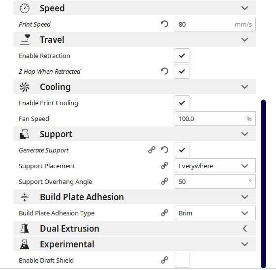
For the speed I set 80 mm/s. A higher speed could have damaged the model.
I enabled the retraction and Z Hop so that the auger would not release material when moving from one blade to another.
I enabled the supports, which are especially useful for the blades, and I set the Brim to make sure the object adhered correctly to the plate.
After clicking on Slice, the program gave me the machining time (2 and an half hours).
I then saved the gcode and set up the machine. I changed the coil that didn’t have enough material for my object and proceeded to make the print settings directly from the machine.
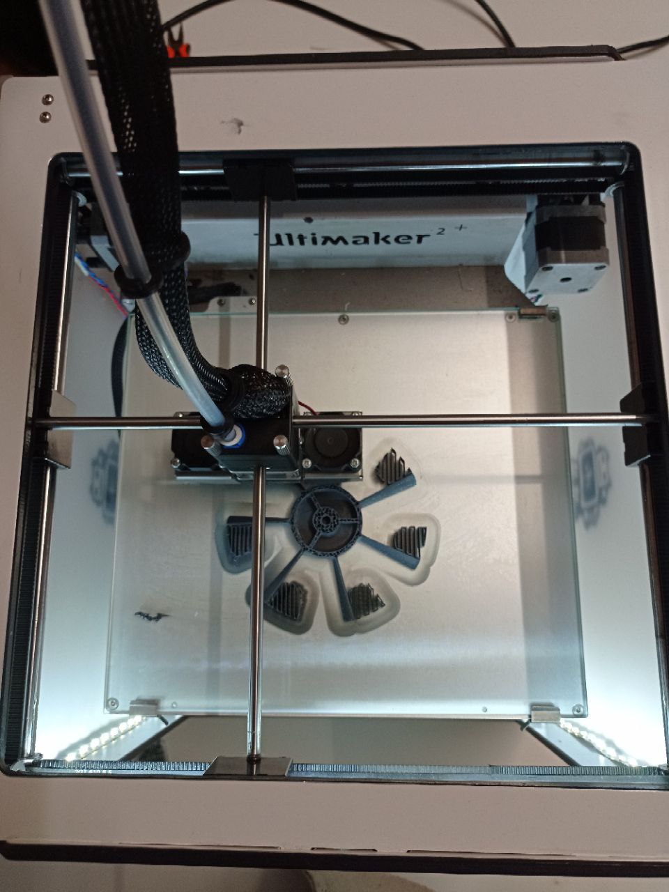
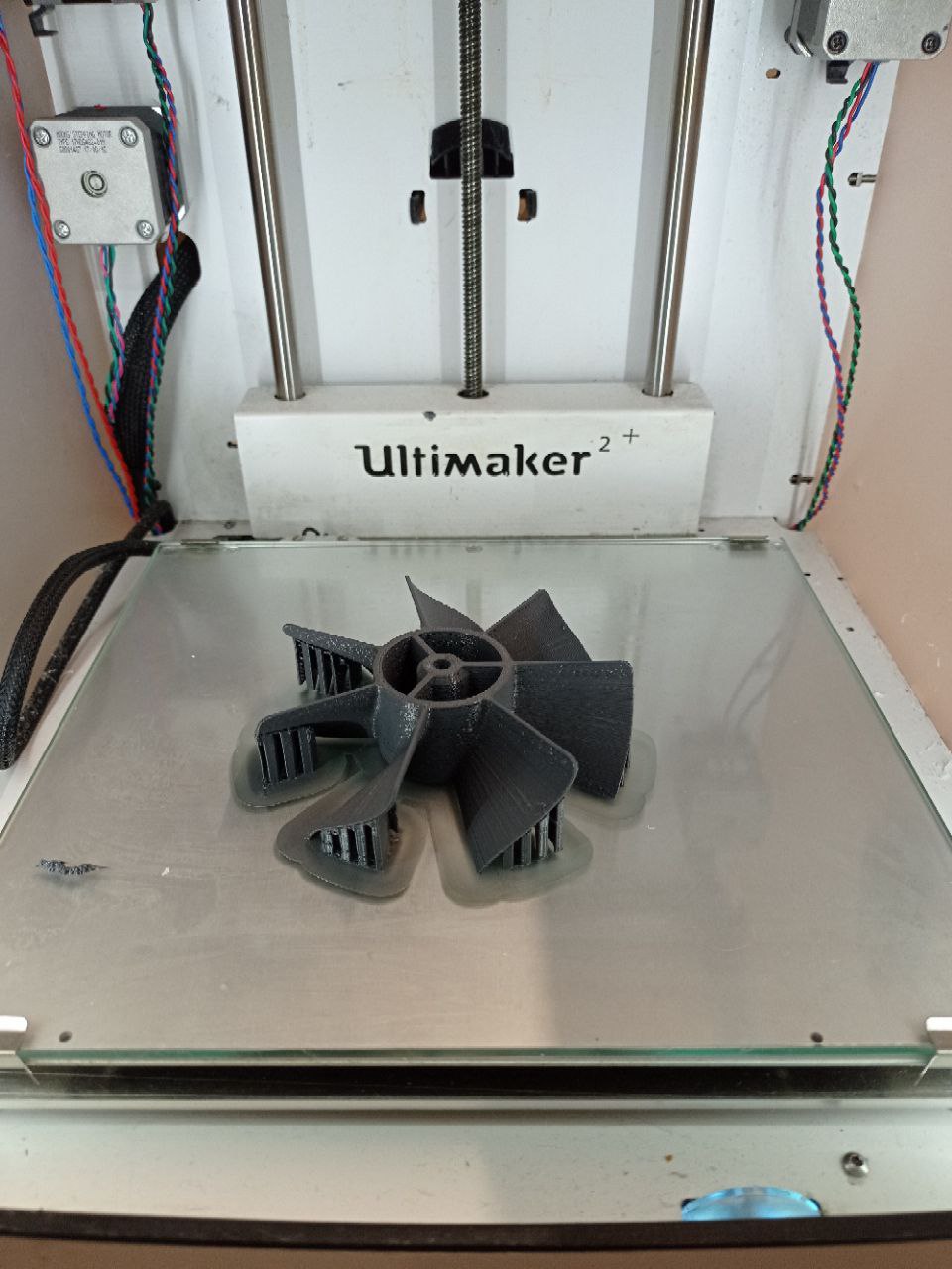
And here is the final result:
PROS AND CONS
To summarize, 3D printing is becoming popular with manufacturers. The demand is growing due to some of the revolutionary benefits that it can provide. This production process offers a range of advantages compared to traditional manufacturing methods: Some examples are:
- Flexible Design –> 3D printing allows for the design and print of more complex designs than traditional manufacturing processes
- Rapid Prototyping –> 3D printing can manufacture parts within hours, which speeds up the prototyping process.
- Print on Demand –> Print on demand is another advantage as it doesn’t need a lot of space to stock inventory, unlike traditional manufacturing processes. This saves space and costs as there is no need to print in bulk unless required.
- Minimizing Waste –> The production of parts only requires the materials needed for the part itself, with little or no wastage as compared to alternative methods which are cut from large chunks of non-recyclable materials.
- Ease of Access –> 3D printers are becoming more and more accessible with more local service providers offering outsourcing services for manufacturing work. This saves time and doesn’t require expensive transport costs compared to more traditional manufacturing processes produced abroad in countries such as China.
Like with almost any other process there are also drawbacks of 3D printing technology, such as:
- Limited Materials –> While 3D Printing can create items in a selection of plastics and metals the available selection of raw materials is not exhaustive.
- Restricted Build Size –> 3D printers currently have small print chambers which restrict the size of parts that can be printed
- Design Inaccuracies –> related to the type of machine or process used, some printers have lower tolerances, meaning that final parts may differ from the original design
- Reduction in Manufacturing Jobs –> reduction in human labour since most of the production is automated and done by printers
Useful links: