12. Mechanical design and Machine Design
- Design a machine that includes mechanism+actuation+automation
- Build the mechanical parts and operate it manually
- Document the group project and your individual contribution
For the last two weeks we have all been working together on the construction of the machine.
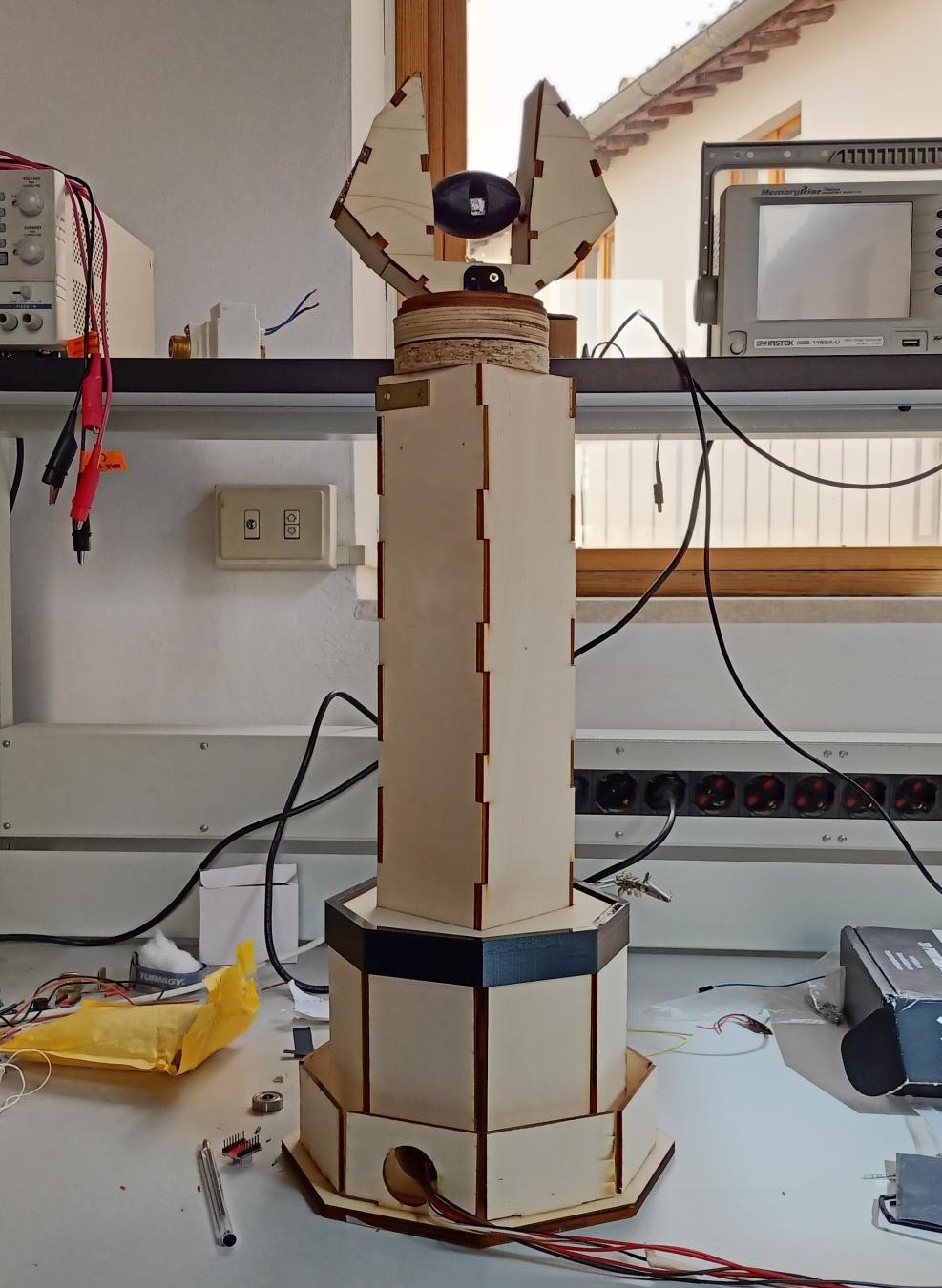
The machine we built was inspired by the film “The Lord of the rings”. We recreated a tower with a rotating head. On top of the rotating head there is going to be a rolling eye with some Neopixels inside in order to give the Sauron’s eye effect. The whole tower is made of laser-cut wood.
My task was to model the gears supporting the motor on Fusion 360 and to design a part of the thrust bearing for the head’s rotation. I also did the design, milling and soldering of the electronic board.
DESIGN THE GEARS
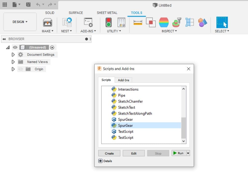
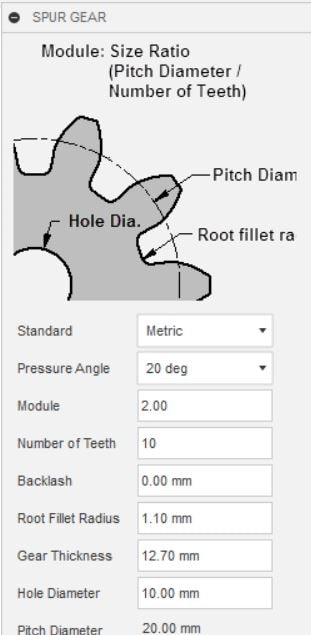
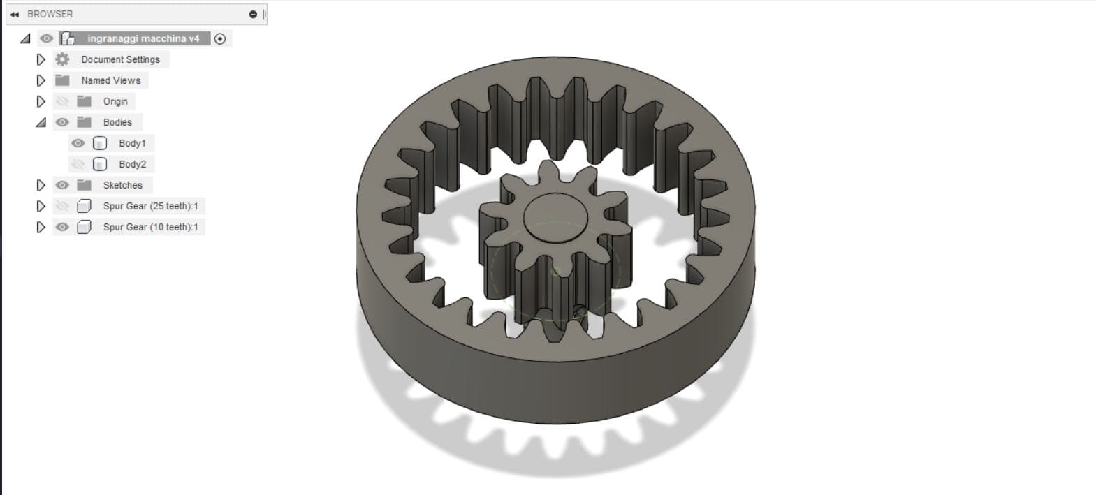
For the design of the gears I used a function of Fusion 360 that automatically draws the model after acquiring the fundamental parameters such as diameter, number of teeth, gear thickness. The aim was to create a gear with a hole in the shaft that could rotate the tower head using a previously modeled bearing with a diameter of 6 cm.
After defining the parameters, I obtained the first gear to which I added the shaft in which the motor would be placed, taking care to draw a hole in the center to fit it in.
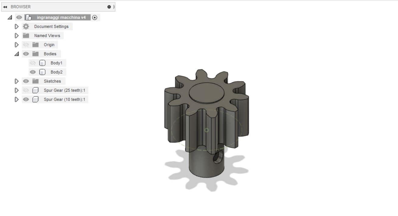
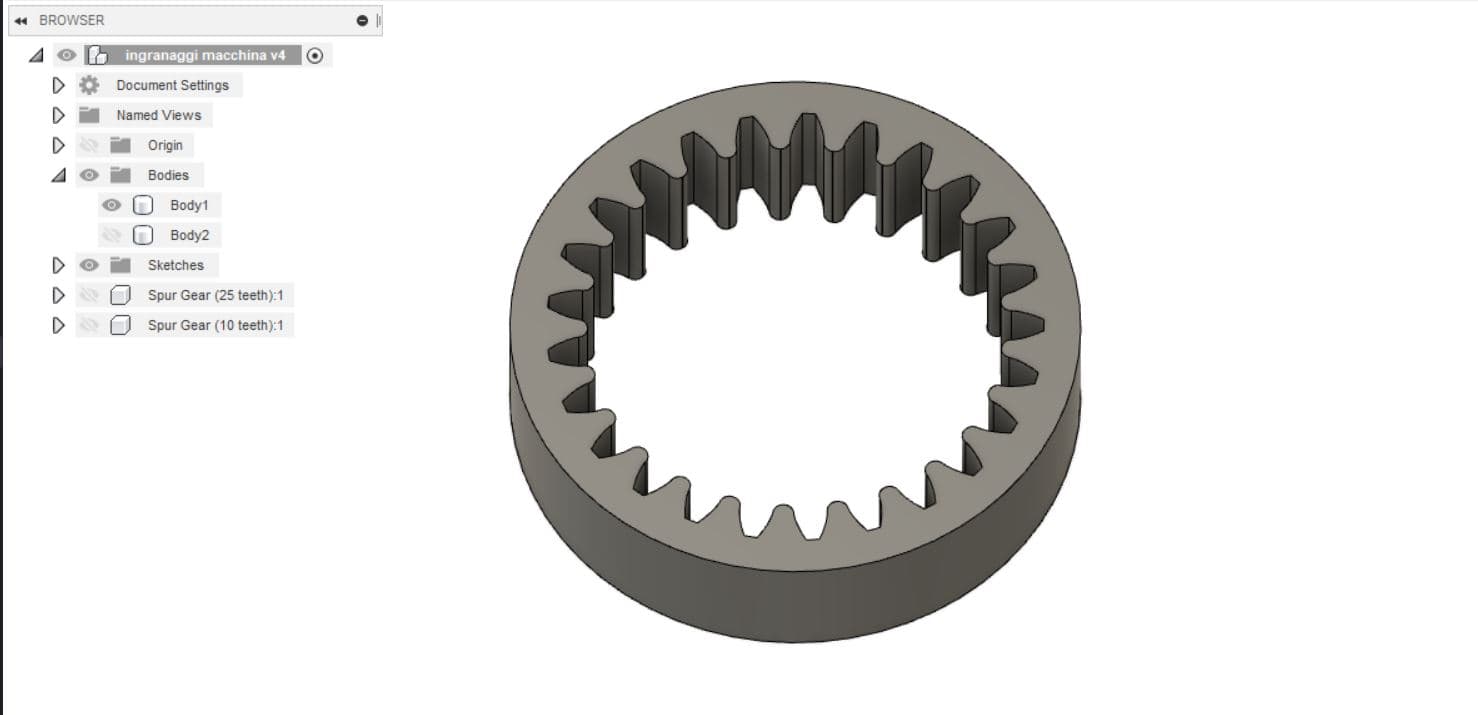
I also designed a larger gear to be placed on the bearing so that it would fit perfectly with the other gear on the motor.
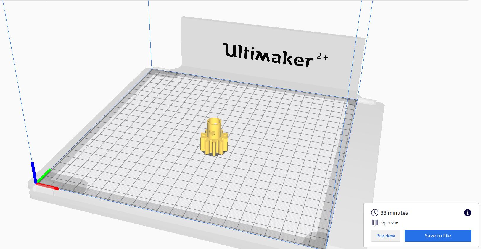
After the design phase, I used Cura to print the little gear and for the big one we used the laser cutter.
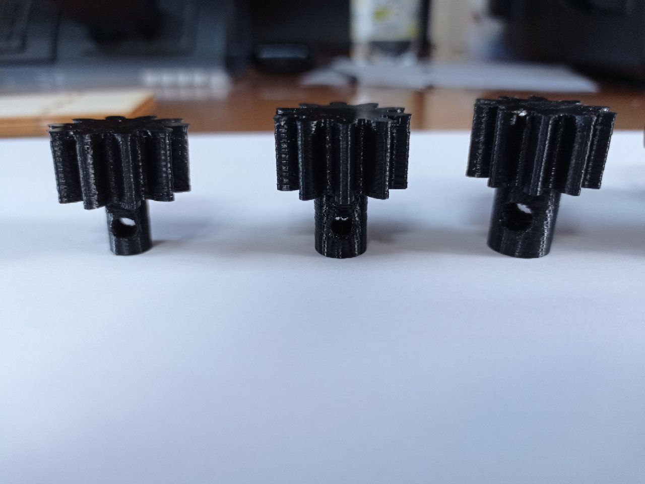
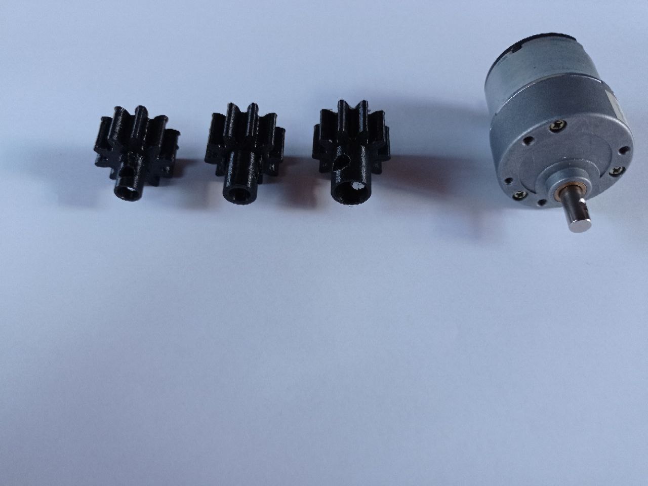
I changed the gears’ dimensions three times because the first time the neck of the gear did not allow the motor to enter because it was too narrow. On the second attempt it was too wide. The third attempt, however, allowed the two parts to be joined perfectly.
DESIGN THE PCB
The most complex part was definitely the design of the PCB. Until then, I had never created a circuit board with so many components, so I heartily welcomed the help of my instructor who gave me advice on how best to organize the work.
The PCB is going to allow the user to rotate the head of the tower, to move up or down Sauron’s Eye and to turn on the Neopixels inside of it.
So, the components to be included in the board include:
INPUT AND OUTPUT + 5 buttons (on/off, right, left, top, bottom) + Servomotor + DC motor + Neopixel
Other elements added to the board are two LEDs, one to check the operating status of the board and one to check its programming capability.
The microcontroller used is the 328p, Attmega with 32 pins.
In addition to this, there is an Integrated circuit 495 to which the motor has been connected and to which the 12 V distributed by the voltage regulator arrives.
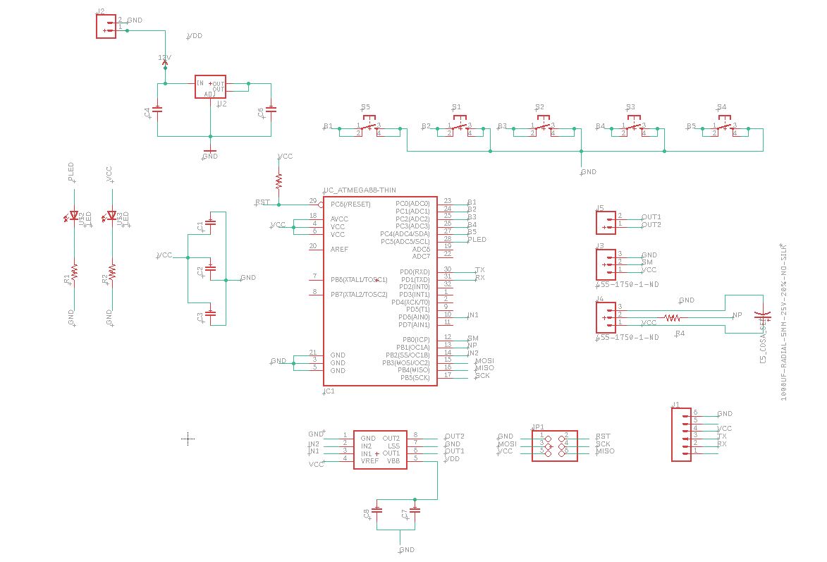
The design was done on Eagle.
This is the schematic view:
And this is the board view:
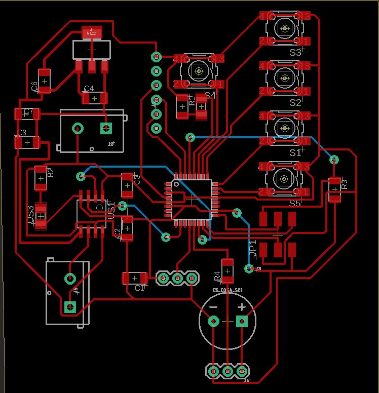
After several attempts to reconnect the various elements, I realised that it was impossible to connect all the elements. So I opted for bottom-level traces, which are marked in blue (two to connect the IC pins to the PWD pins on the microcontroller, another to connect the reset pin to the resistor, and the last to connect a VCC that had not been connected with the others).
After creating the png of the board, with the help of Alberto, I used Photoshop to create the 3 files to be processed with the mods: one for the traces, one for the outline and the last one for the holes.
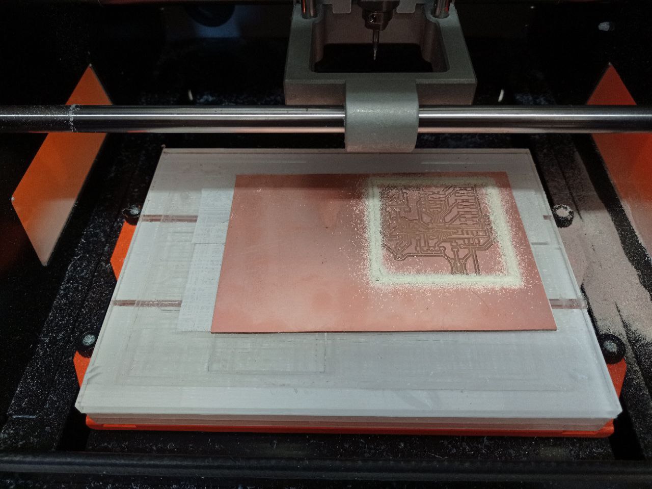
MILLING PCB
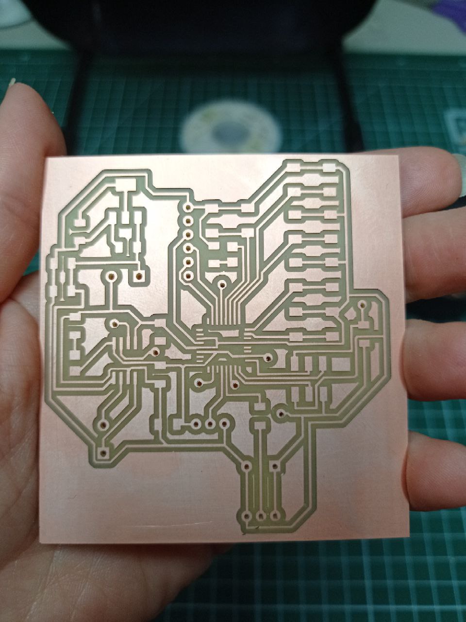
There were two hiccups during the milling process. In the first case it was a distraction error due to the fact that the tin plate used was wrong as it had the copper layer both above and below. The second hitch was related to a broken end mill tip, which was quickly replaced and the milling process was able to continue without any problems.
This was the result:
SOLDERING PCB
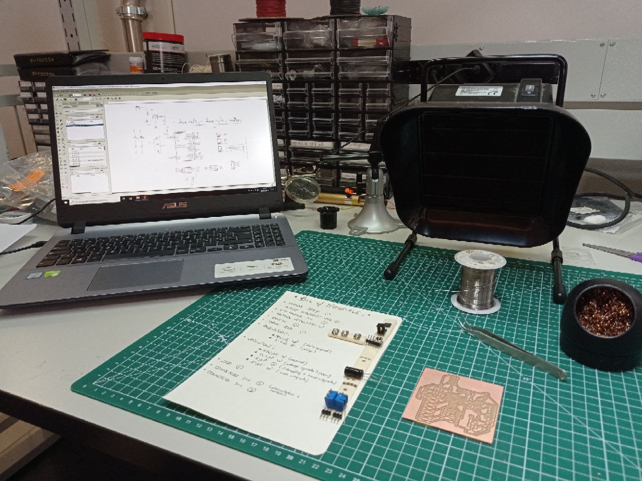
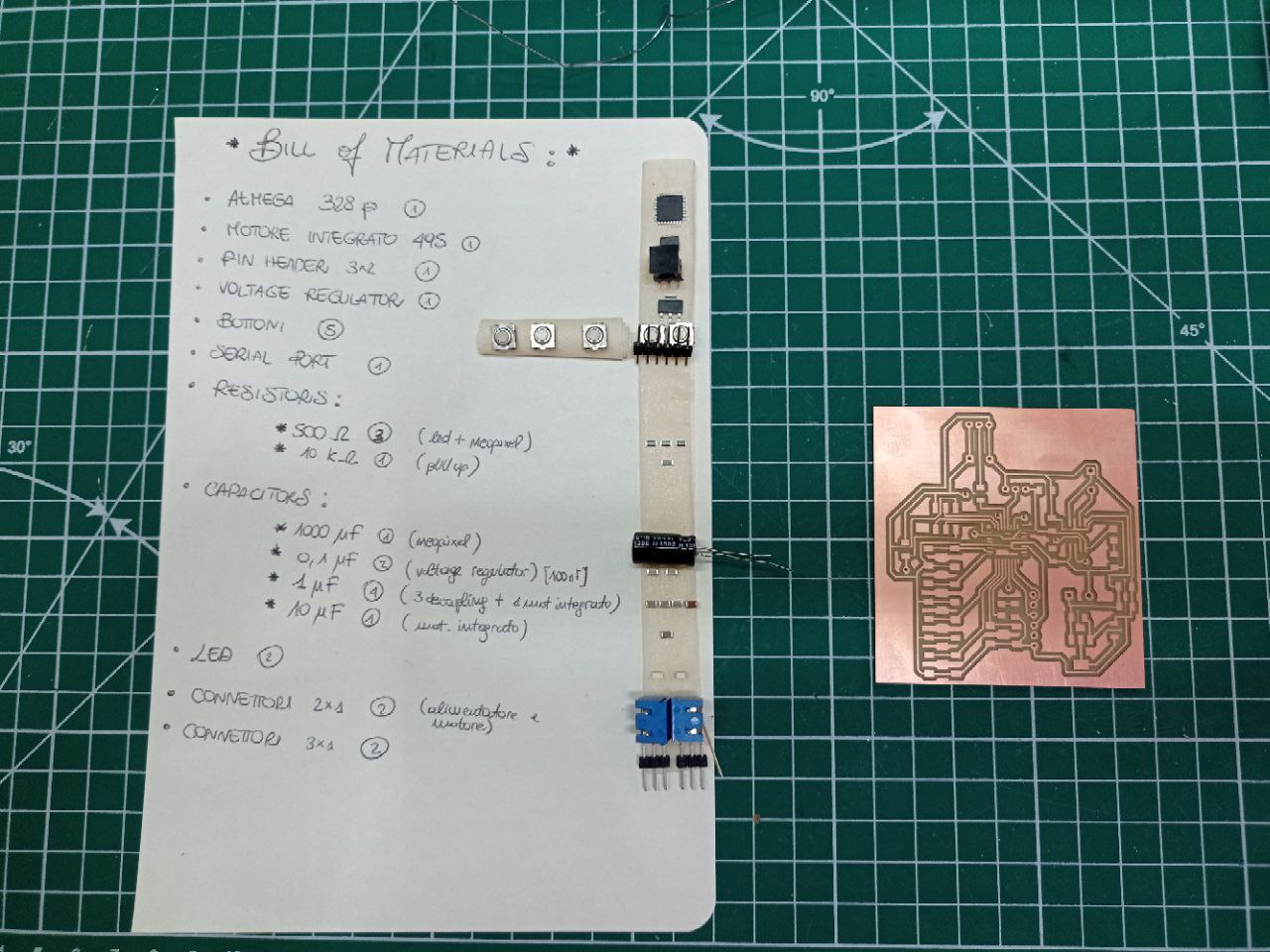
After checking that the traces were well connected to each others, I collected all the components and I wrote the bill of materials, and after taking long breaths I started soldering.
Everything went well, although I think I became even more blind than before.
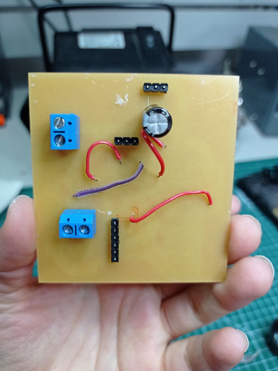
To connect the tracks of the bottom layer I asked for the help of my best mate Slava who, with patience and hands that were certainly less shaky than mine, managed to solve the problem.
This is the final result:
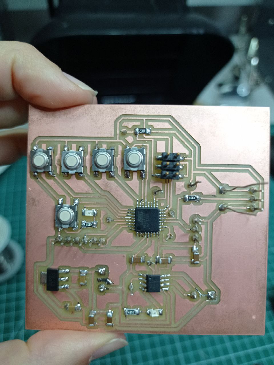
After assembling all the pieces the result was this:
In the following video you can see the eye move up and down and turn left and right: