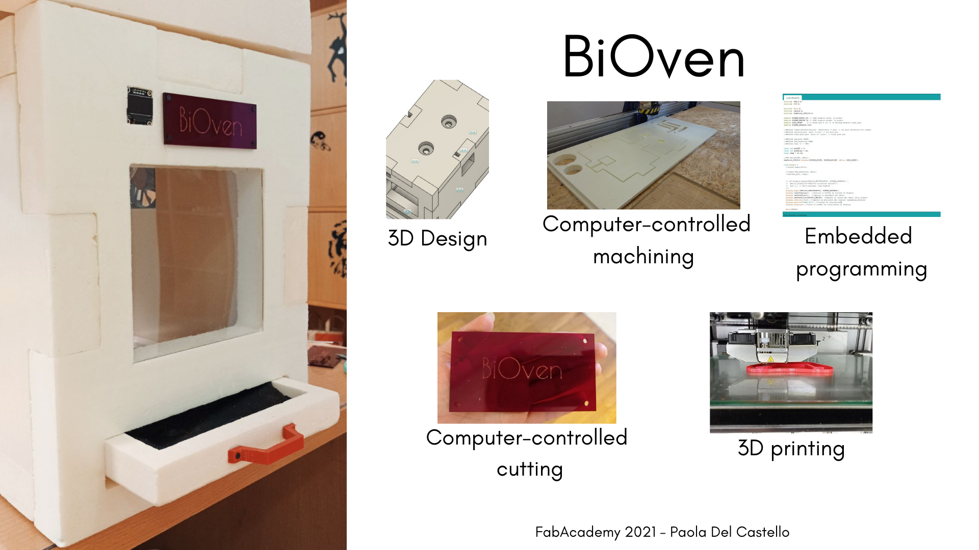
Final Project - BiOven
02/02/2021 Principles and Practices - CONCEPT
And now the hardest part: thinking about the final project.
It was complicated to define an idea, in these days I had billions of ideas… one less feasible and absurd than the other!
So I decided to start with something that could be useful, something that I need it.
But let’s start from the beginning.
I’m working on my final thesis project on bioplastics, It’a an exciting work, creative, sometimes “dirty” but satisfying … But in the same time very complicated if you don’t have the right tools to get the job done.
I imagine a world where sustainability is everyone’s priority. I imagine a world where everyone is aware of the responsibility for their own actions, where everybody live in a “sustainable” way. So I tried to do my part, choosing to try to create an alternative material that could replace animal skin but at the same time that had its roots in the territory where it is produced. I had to chose a waste product to give a new and different life to, in respect of circular economy.
And after attempts, failures and hard work, I was able to find a “recipe” and a product that could make me reach my goal: wine’s waste. Who decides that Brunello has to be just a wine?
So, I continued my research, in the hope of being able to make small changes to the mixture and ingredients enough to make it an acceptable alternative.
Among the biggest difficulties I faced, there are surely the timing of the drying, which strictly depend on the temperature and the humidity level of the air.
And for this reason I have often found myself in such situations:
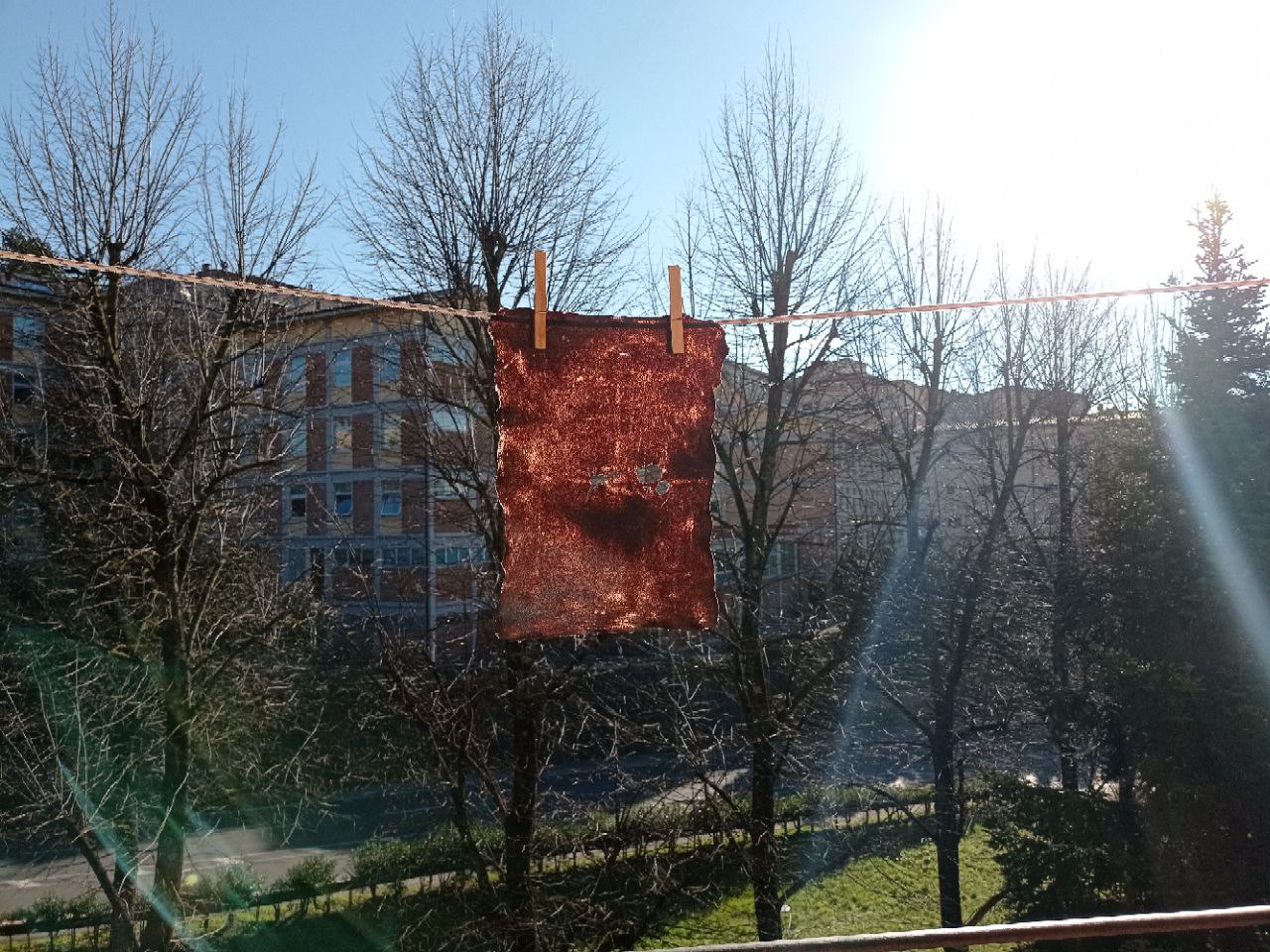
And so I thought to create a tool able to make the production process easier and faster: create an evaporative sheet former for bioplastics.
The core project is as follows:
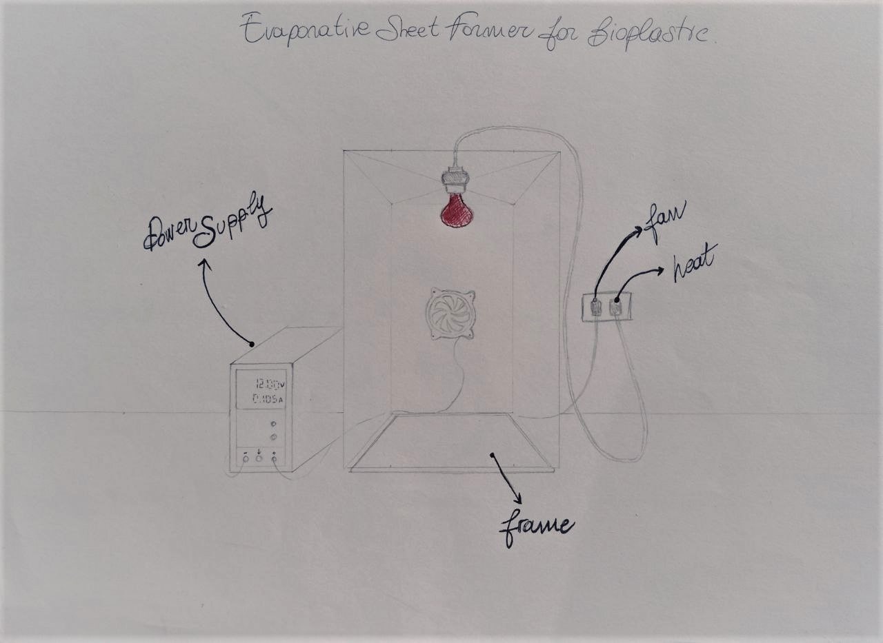
- Plexiglass structure opened at the bottom
- A frame that you could take off in which to pour the mixture to dry
- Power Supply to turn the fan on and off
- Light source for the heat
In addiction to that, I thought to add a feedback system. The values that I would like to obtain would be:
- temperature
- humidity rate.
Such feedback could be returned both locally (thanks to a display placed on the structure itself) and remotely with a notification on an app accessible by smartphone.
The idea would be to allow the app to change the parameters even remotely.
Will this be possible? I don’t know… but for sure We can make (almost) anything.
3D CAD DESIGN
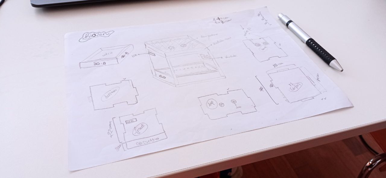
In the end I decided to carry on with the initial idea of my project, trying to revise some practical details such as the materials to be used, the structure to be given to the box, the components to be inserted.
I then redesigned the project, which would then be more or less like this:
Unfortunately, I did not find much material to support me. Creating bioplastics is a niche activity involving DIY techniques so everyone chooses the best equipment to achieve their own result. In the little material I was able to find, I came across the webpage of a Fabricademy participant who has created a tool for laying out bioplastics. In particular, inspiration came from looking at the work of TheShellworks, who has created various machines to help transform lobster shells into bioplastic.
I decided that instead of building a wooden frame on which to place the bioplastics, I would build a drawer with a 3D handle inside which to place a sheet of glass on which to place the bioplastics.
So, first of all I started to design the XPS box for my BiOven.
After drawing the box on paper and defining the various measurements required, I started modelling it on Fusion. The operation was relatively simple and after drawing each face of the box and making the relevant joints it was easy to see whether the box had been drawn correctly. The thickness of the individual walls is equivalent to the thickness of the polystyrene, i.e. 4 cm.
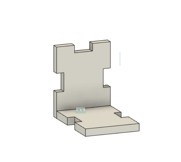

In addition to the individual faces, I also drew the drawer on which to place the bio-material, creating a recess in it on which to place the glass plate. I will also attach a handle to the drawer to make it easier to slide.
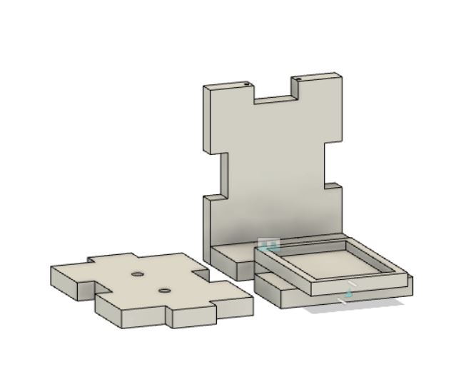
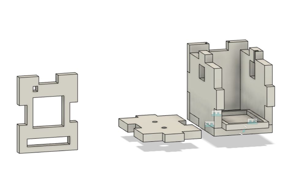
On the upper part of the box I have created holes for the light bulbs to pass through. The upper part of the box will collect all the electrical cables, so it will be covered to prevent them from being visible outside.
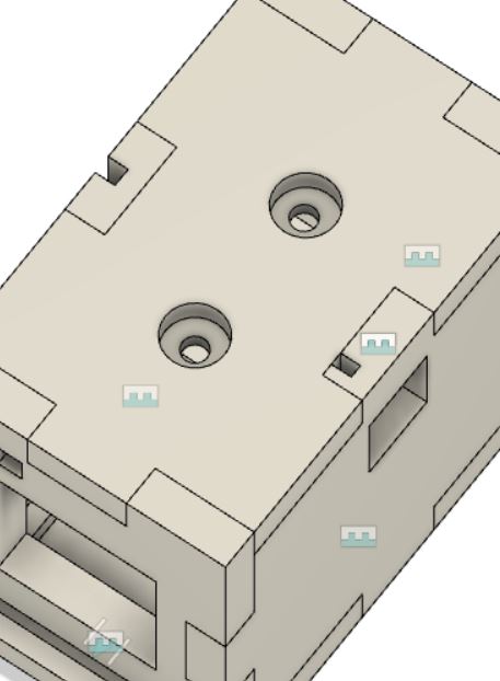
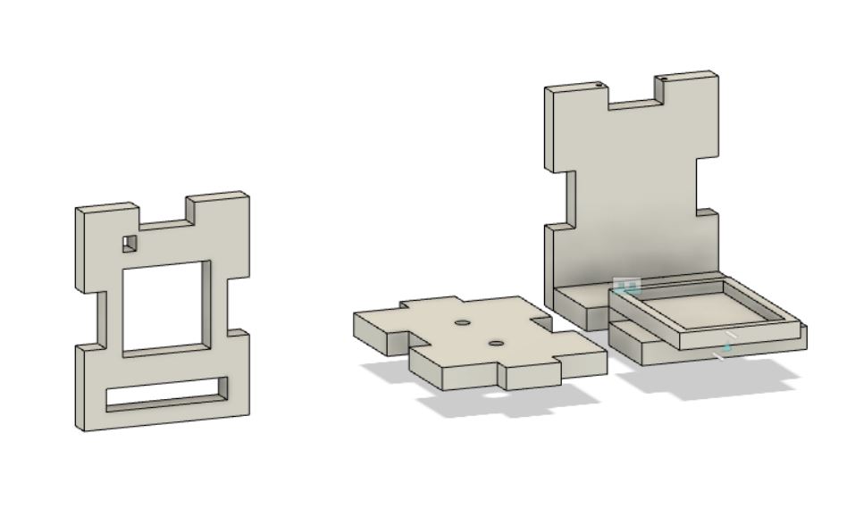
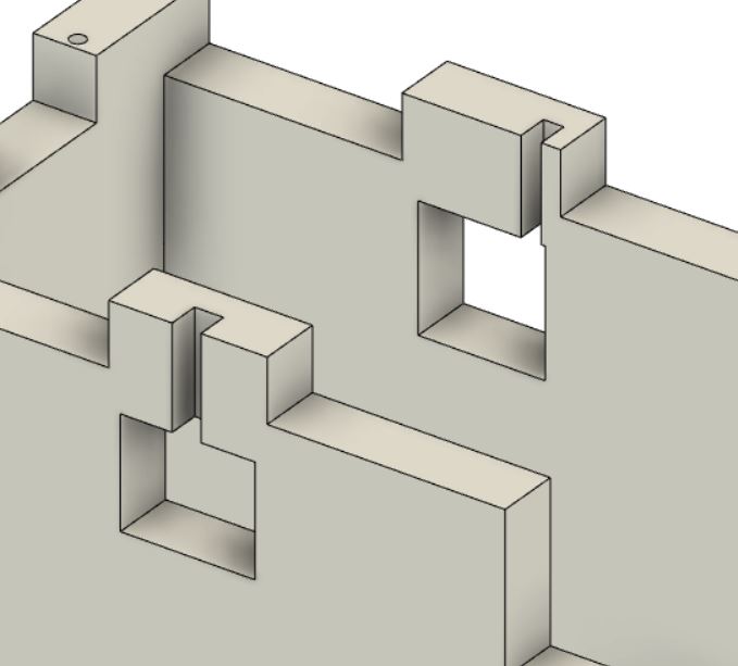
On both sides of the box I have left some empty spaces where the fans can be inserted to allow air to circulate inside the box. I took care to create small empty spaces towards the top to contain the cables of the fans and make them escape in the upper part of the box where my pcb will be placed.
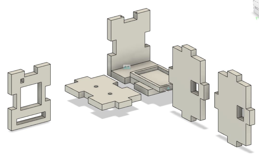
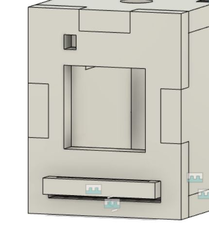
The front of the box has a small square at the top in which to insert the I2C LCD screen and an empty space in which to place another sheet of glass to allow visibility of what is inside the oven.
The final model result as follow:
ELECTRONICS
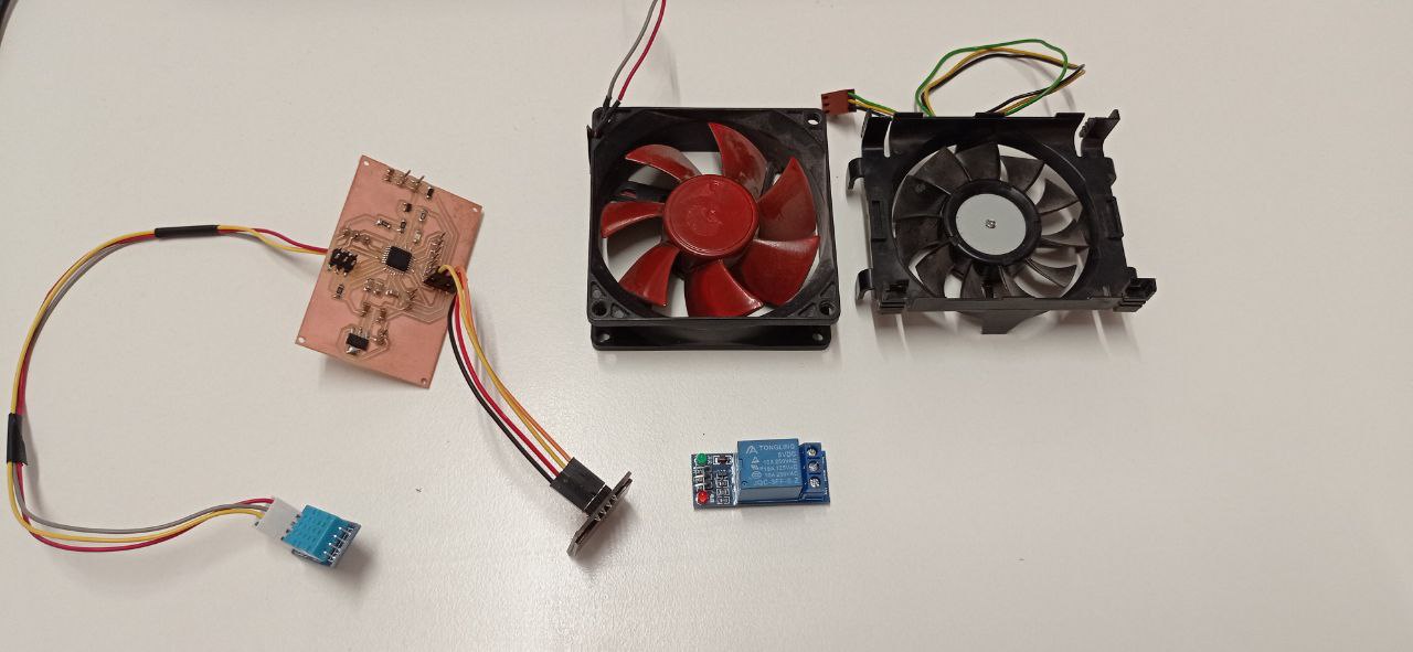
The task to be performed by my pcb will be to measure temperature and humidity, using a sensor and returning the values to an I2C LCD screen. In addition to this, the board will control the movement of the fans, and through a relay it will be possible to connect a switch to the circuit in order to check their switching on and off.
The basic components of the board are:
- Atmega 328
- ISP
- FTDI
- LCD I2C
- Relay
- Voltage regulator
- Power supply
- DHT sensor
- Fans
- Mosfet
To make it easier to understand the functionality of the board, I have drawn a sketch of what will be my pcb:
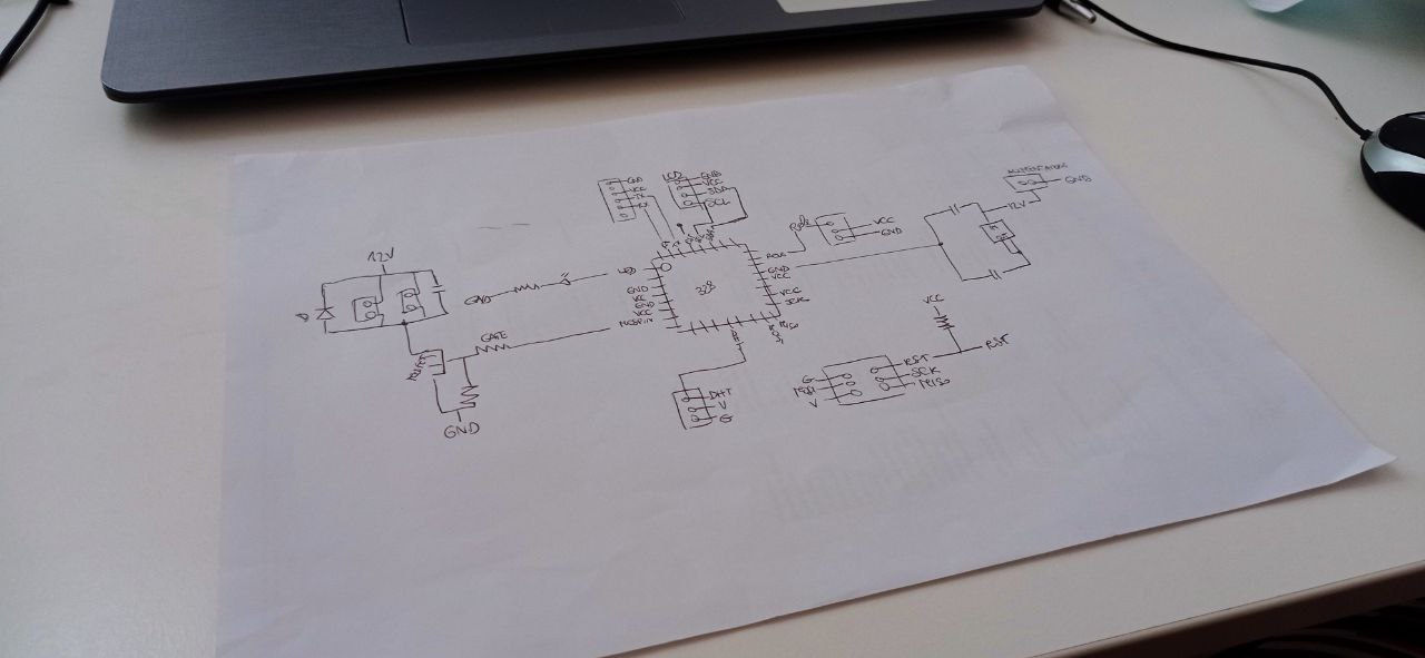
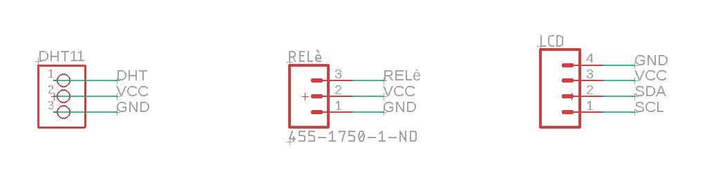
I then start to work on Eagle to find all the components. The schematic looks like this:
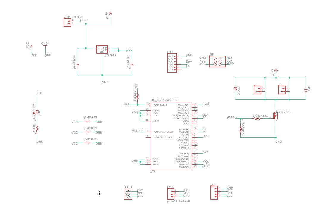
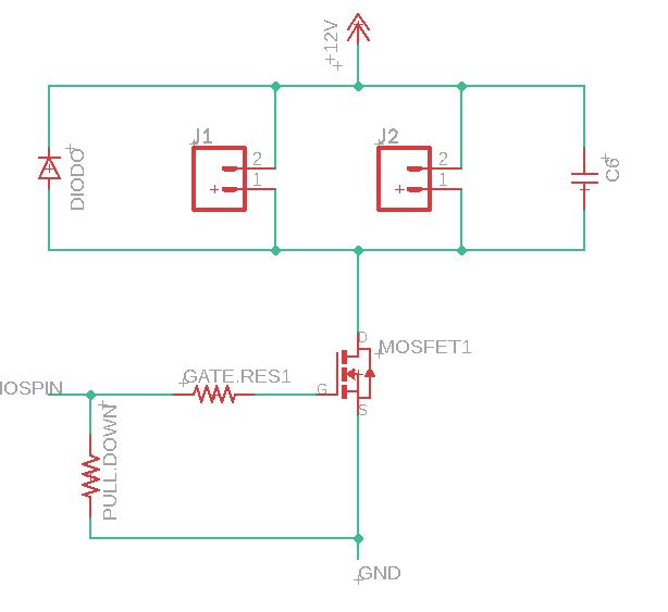
The section dealing with the movement of the fans consists of two terminals to which the fan cables, a diode and a capacitor are attached. A mosfet is then connected to these, which is a device that switches or amplifies an electronic signal. The mosfet is connected to the pin, gnd, and 12 V. Between the mosfet and the pin is a gate resistor, and between the mosfet and the ground is a pull-down resistor.
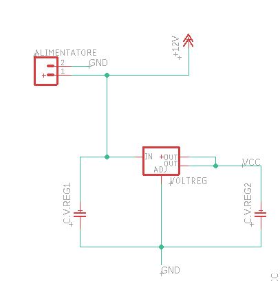
Then there is the voltage regulator, whose job is to receive a high voltage input and then lower and stabilise the voltage to the level required by the electronic device. It is then connected to a power supply from which the 12 V is fed, to two capacitors and to gnd.
The sensors connected to the microcontroller pins will be the DHT for measuring temperature and humidity (pin, vcc, gnd), the relay (pin, vcc, gnd) and the LED (gnd, vcc and SDA and SCL for the communication protocol).
In addition, I have inserted a led with a resistor to check whether the board can be programmed. There are also the 3 decoupling capacitors and the resistor connected to the reset pin.
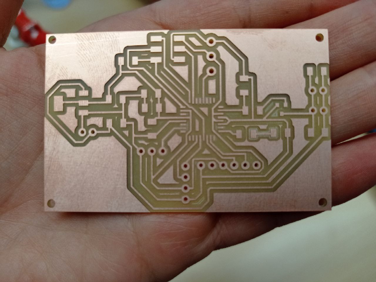
At the end the board looks like this:
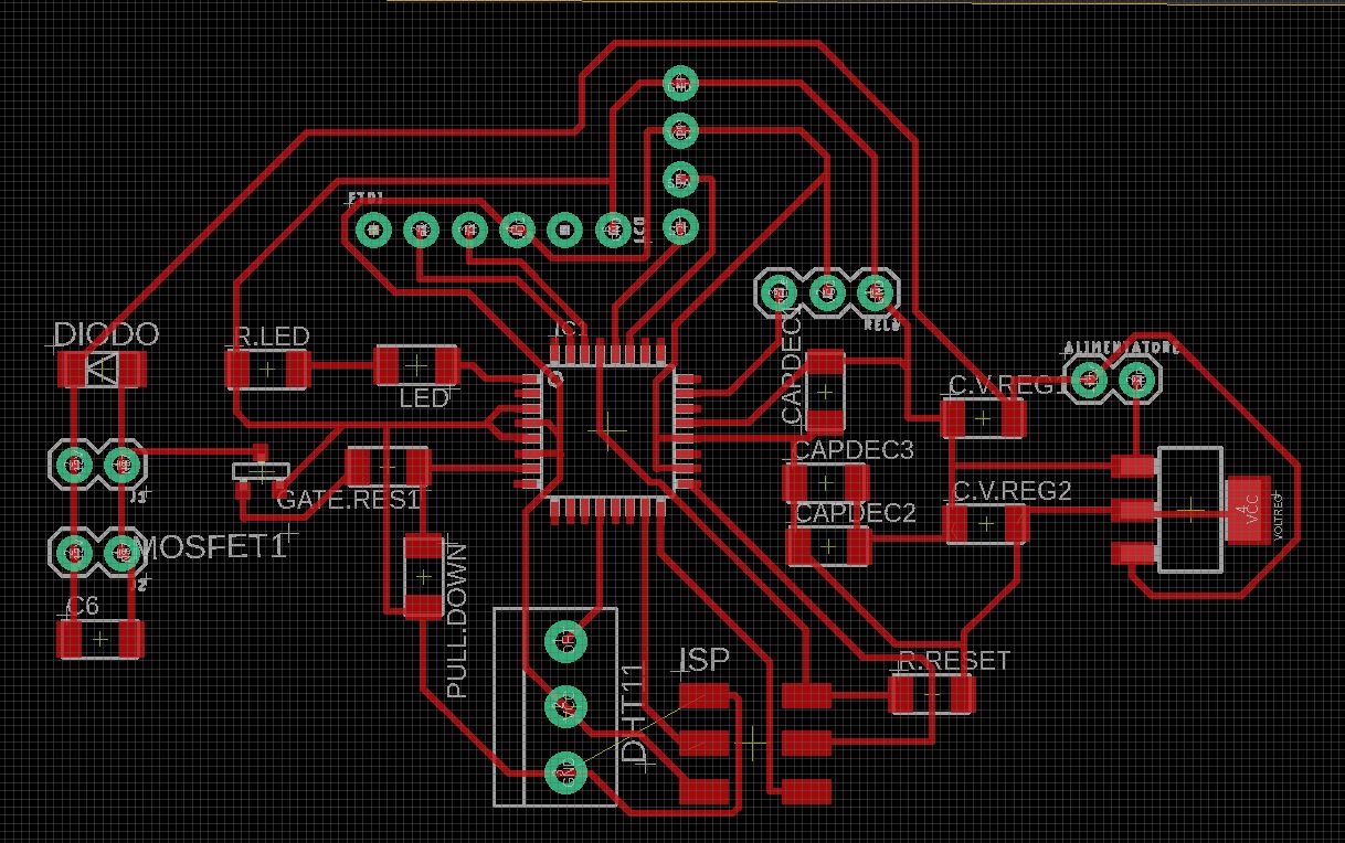
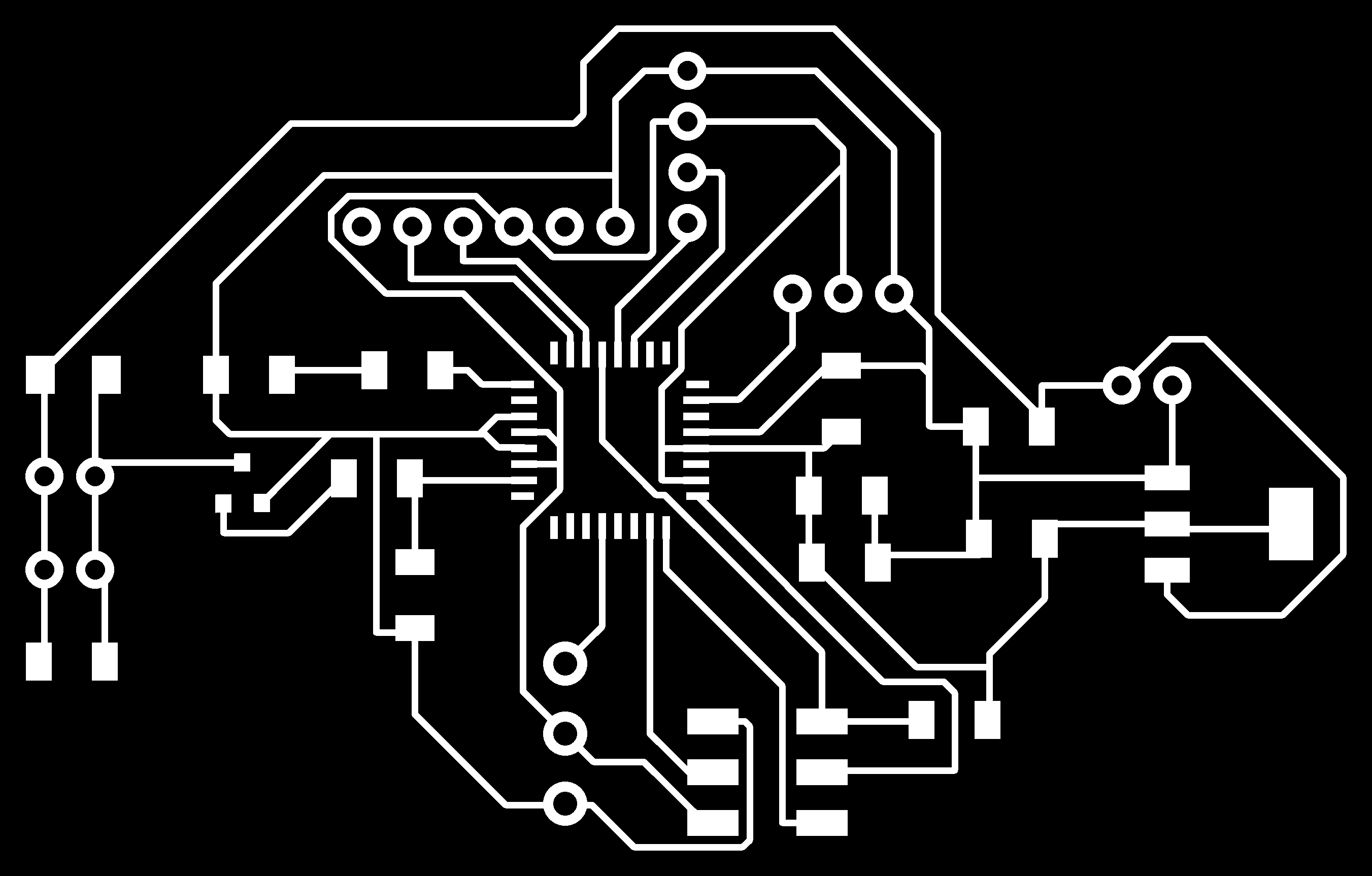
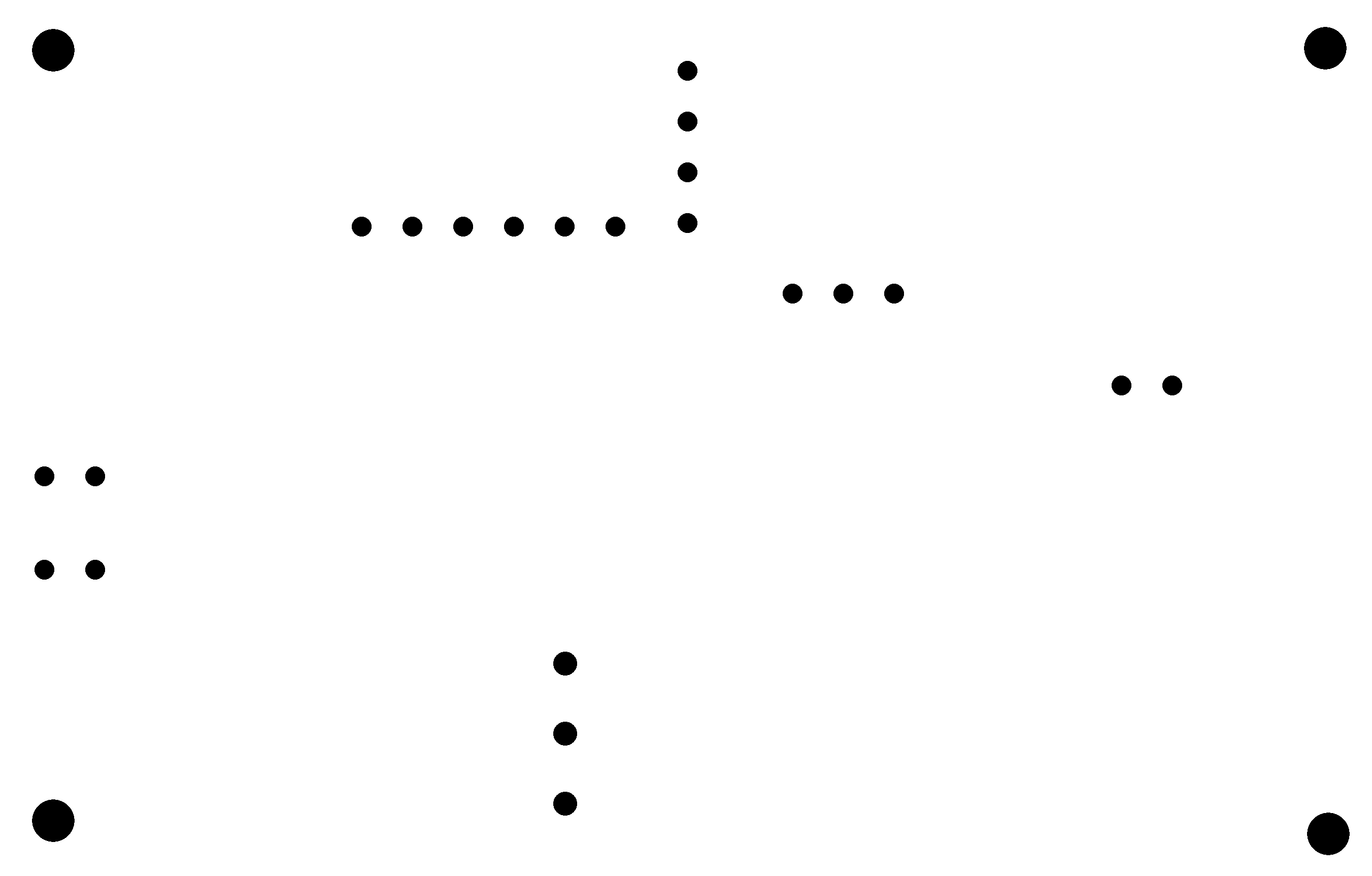
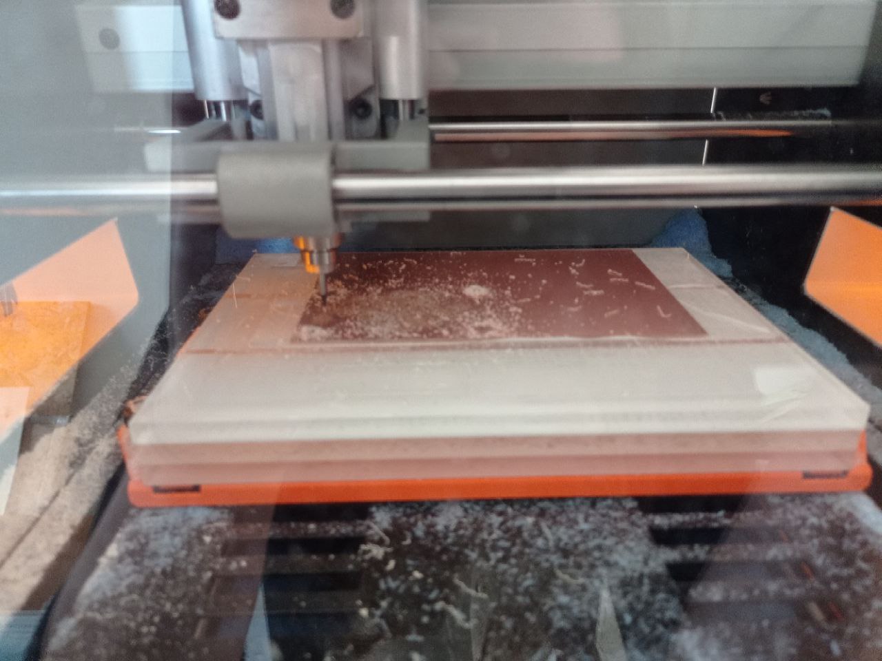
I then export the png file and I created the traces, outline and holes file using GIMP. I also drilled 4 larger holes in the 4 corners of the board in order to screw it to the box.
I then created the mods files and sent everything to the milling machine. I had no problems at this stage and everything ran smoothly.
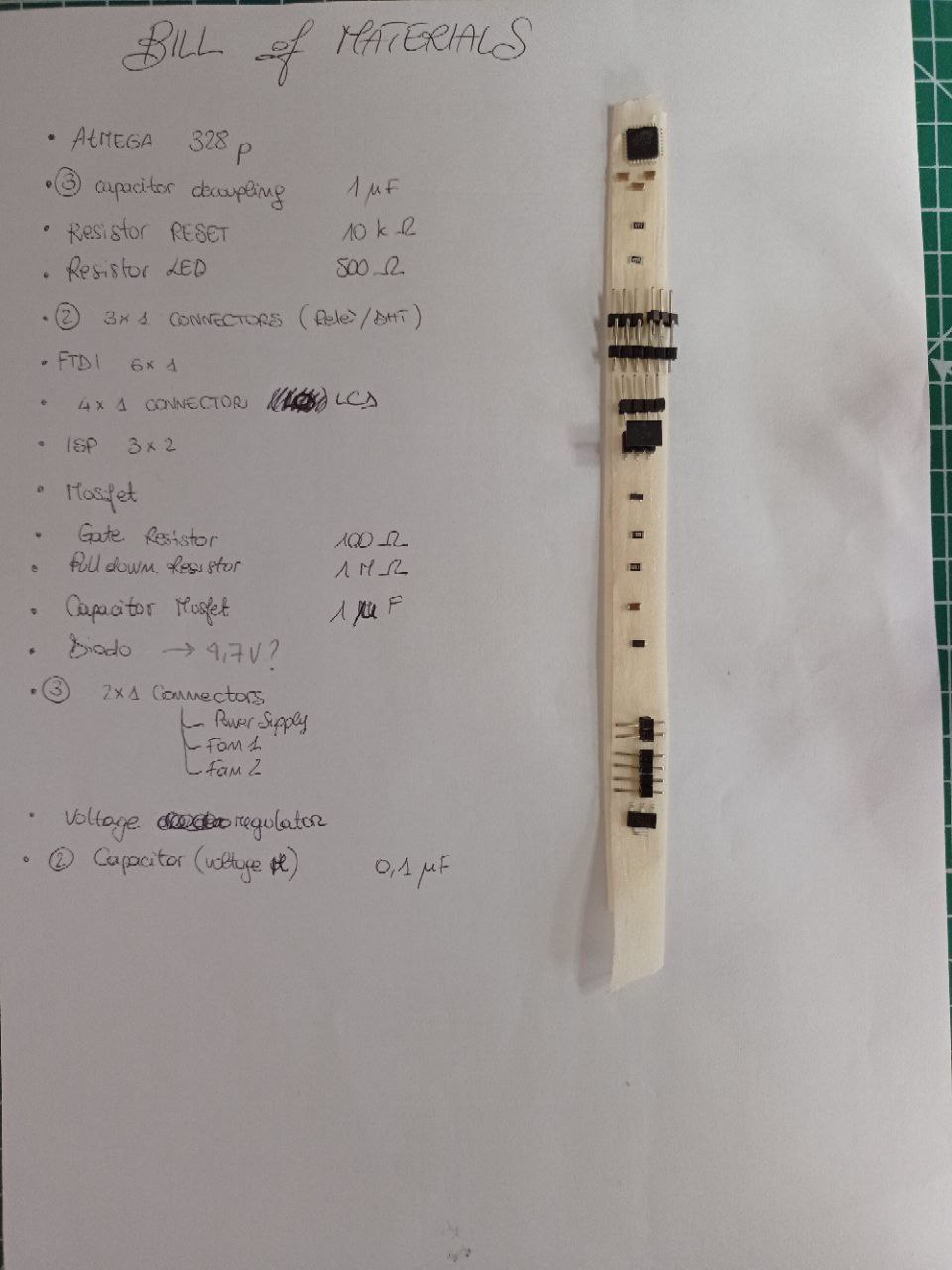
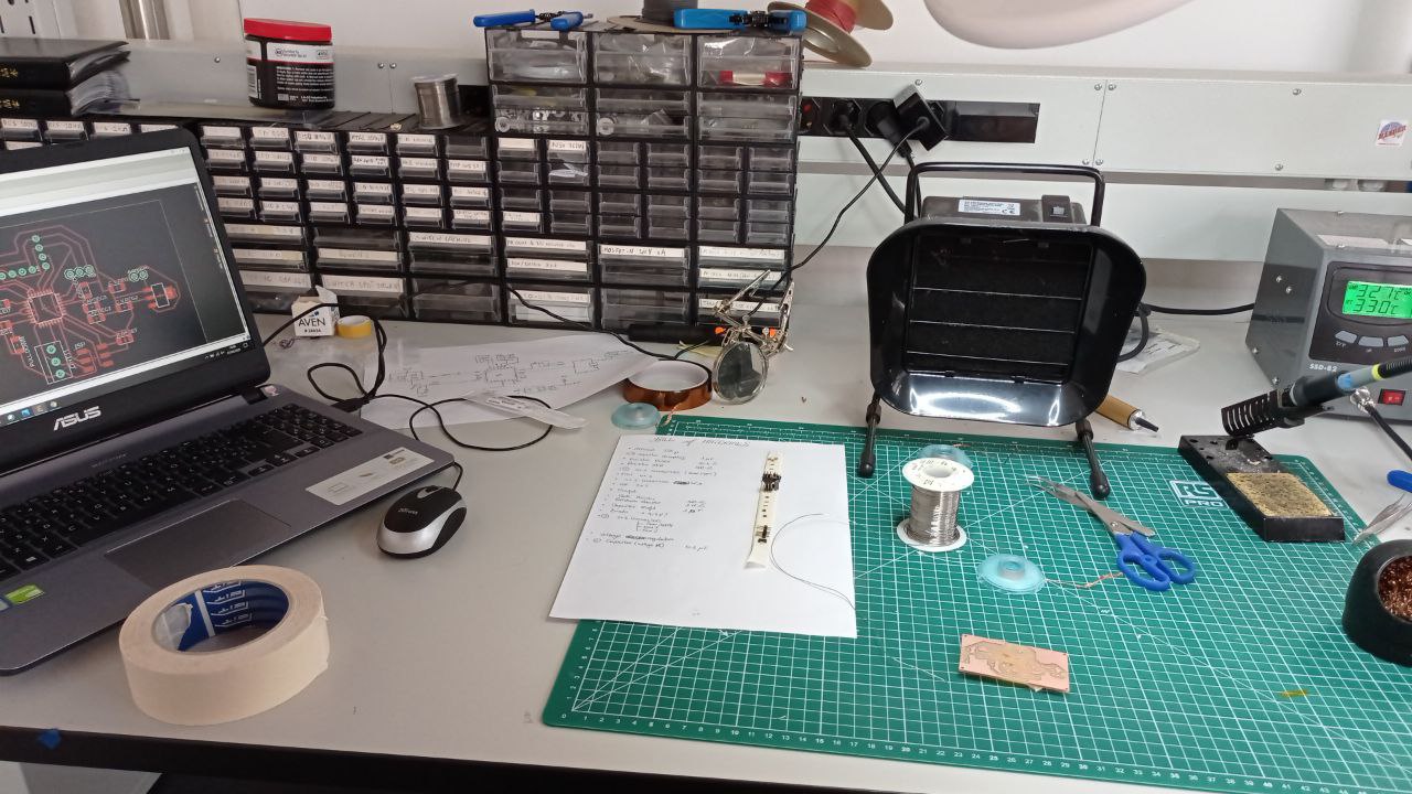
I created my bill of materials and collected all the components to be soldered.
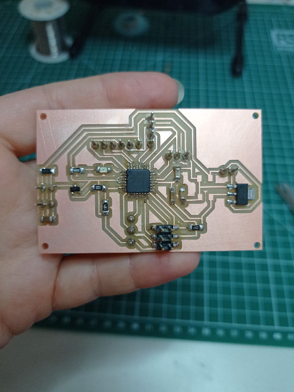
Unfortunately when I tried to program it, it would give me an error and wouldn’t let me compile the board. After a long debug with my instructor, we came to the conclusion that the microcontroller was not working at all. I initially tried desoldering the old microcontroller to place another one, but the process was complicated and the new soldering was not the best. So I decided to repeat the whole process by milling a new board and re-soldering the components. Fortunately, this time there were no problems with the programming so I verified with the simple sketch of the blink led that the board was working.
After verifying that the microcontroller was alive, I started to connect the different sensors to the board to check their functionality through test sketches.
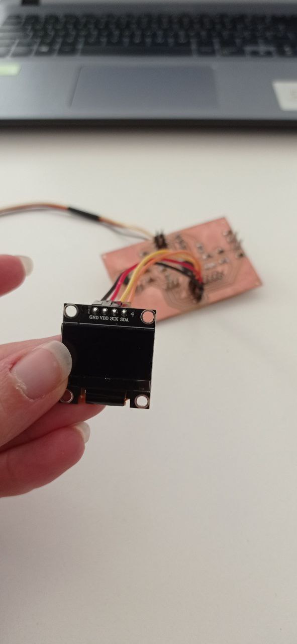
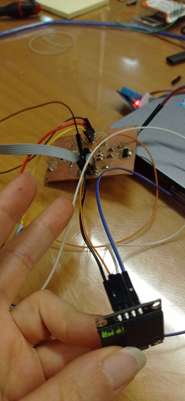
I then connected the lcd board, which gave me several test images and text. To test the screen, I downloaded the Adafruit “SSD1306” and GFX libraries (for graphics) and started one of the test sketches suitable for my screen type.
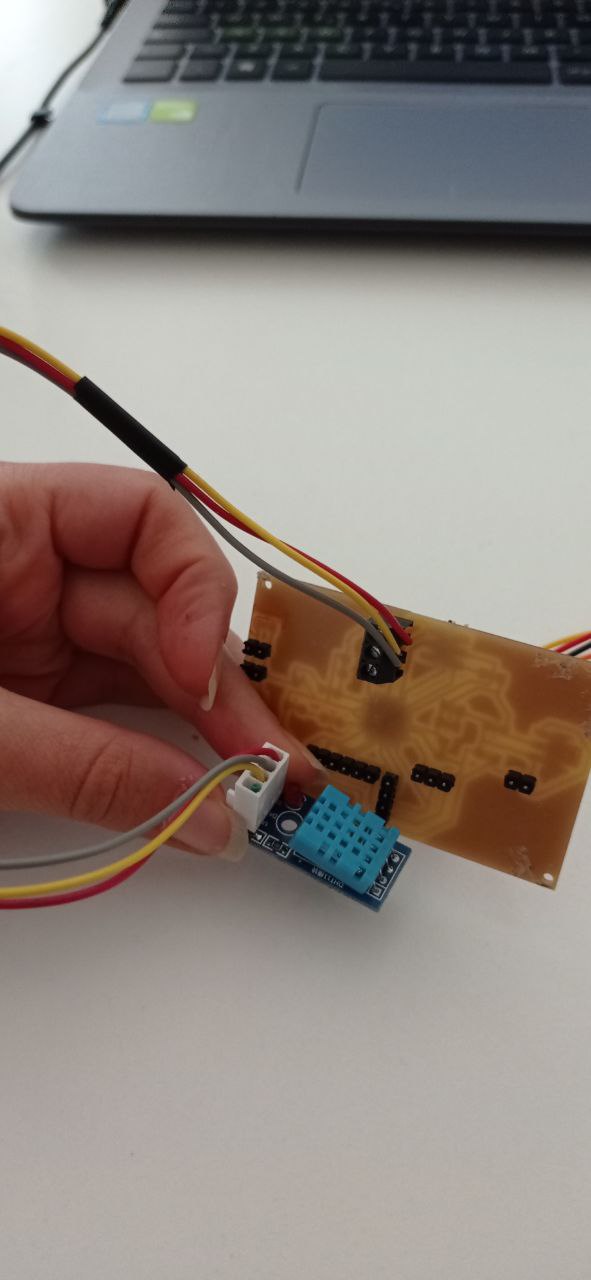
I then connected the dht to the terminal on the bottom of the board.
PROGRAMMING
The code includes the use of different sensors therefore also different libraries: LCD, the fans and the DHT sensor.
The objective of the code is to return the temperature on the screen and arrived at a certain value, automatically turn on the fans to eventually lower the temperature if it is too high.
After checking with a simple blink code the possibility to program the board, I loaded the following code:
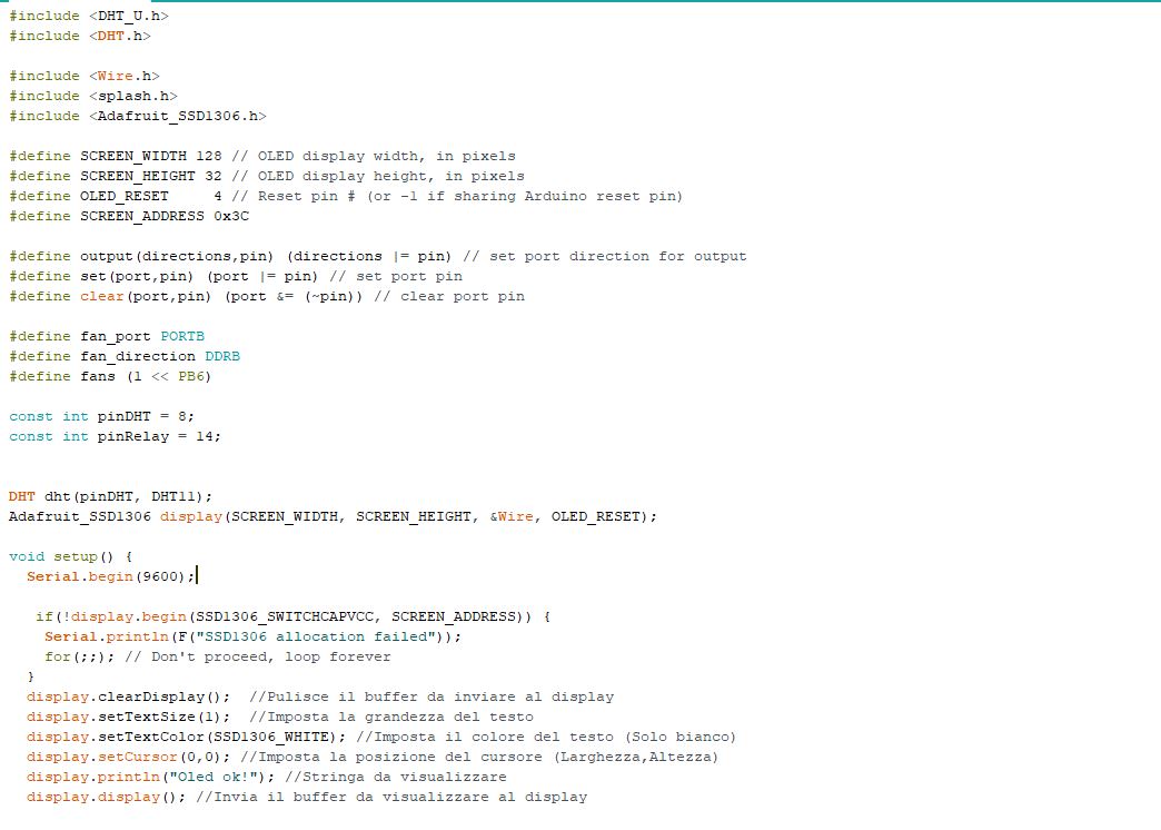
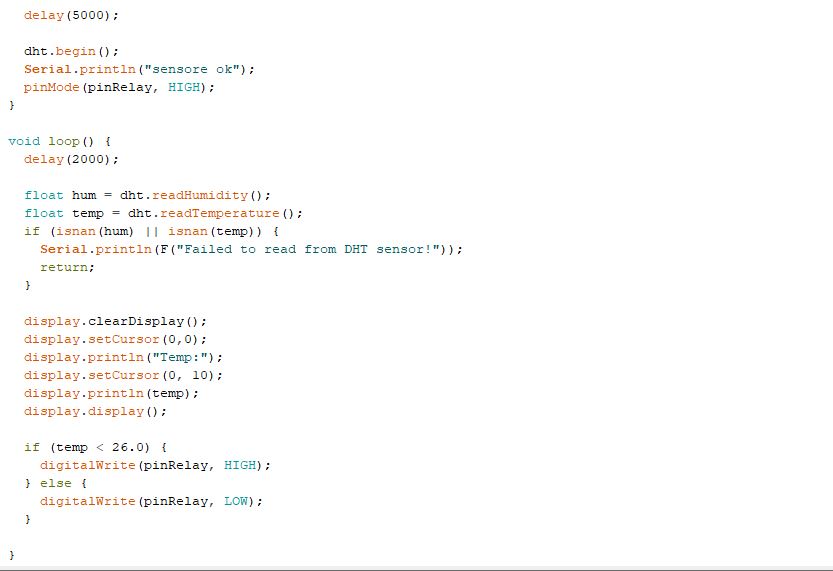
And the code worked!
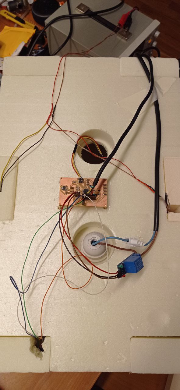
I then set up the board and sensors on the BiOven:
In the following video you can see how the prototype of my BiOven works:
You can download the files here: