9. Embedded programming
Group Assignment
To view group assignment please Click Here
Introduction
In this assignment I am required to build a circuit with a micro controller, where I program it to read a signal from a button or a digital input and control an electrical or electronic load as an output from the chip by programming it to do so. I have to do that using various programming platforms of my choice. therefore I chose to use the following programming platforms

- Arduino IDE
- Platform I/O plugin on Atom or Visual Studio Code
Inputs & Outputs
now before I start implementing the circuit, let me explain something in my own words, What are inputs and what are outputs ?
inputs and outputs are both electrical signal between two voltage levels 0 volts that resembles logic (0 or LOW or false) and +5 volts in case of Arduino UNO resembles logic (1 or HIGH or true), just a note for other microcontrollers that works with different voltage levels than Arduino Uno the logic 1 is the supply voltage of the microcontroller (VCC or VDD) in most cases +3.3 volts.
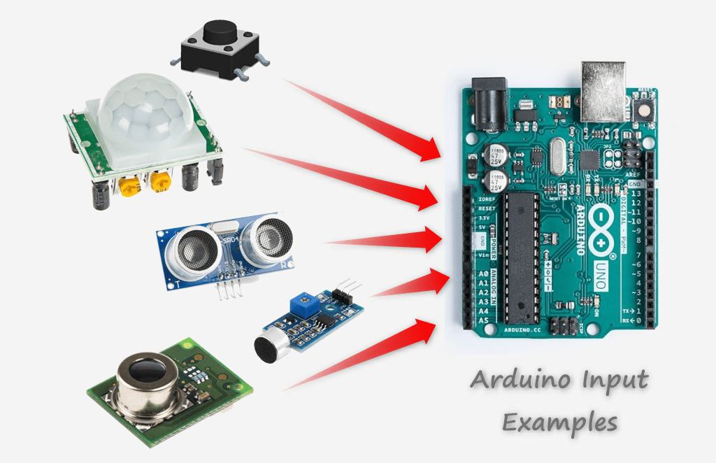
(digital) input : an external signal caused by event on a mechanical device like a button, or toggle switch or a digital sensor that is feed to the microcontroller via I/O pin which is configured by software as an input pin in order to read the signal value (logic 0 or logic 1) by software.
(analog) input : an external signal caused by a variable change in voltage that is between supply voltage VCC and GND, that doesn’t resemble logic levels but it resembles a value to be processed by the microcontroller to make sense to the software written by the (person) programmer. the value can be calculated by the following formula
Value = ((microcontroller supply voltage)/(adc sampling resolution)) * (the voltage of the signal)
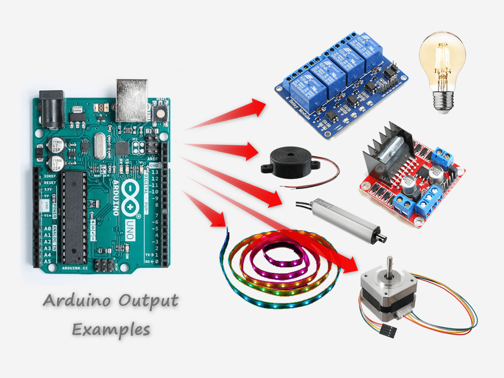
output : an internal signal generate within the microcontroller via software and thrown out on a digital I/O pin that is configured by software as and output pin, in order to give an electrical signal to control and electrical or electronic devices or actuators or transducers logic 0 is (0 volts), logic 1 based on your microcontroller supply voltage VCC or VDD (+5 volts or +3.3 volts).
Arduino Pinout Diagram
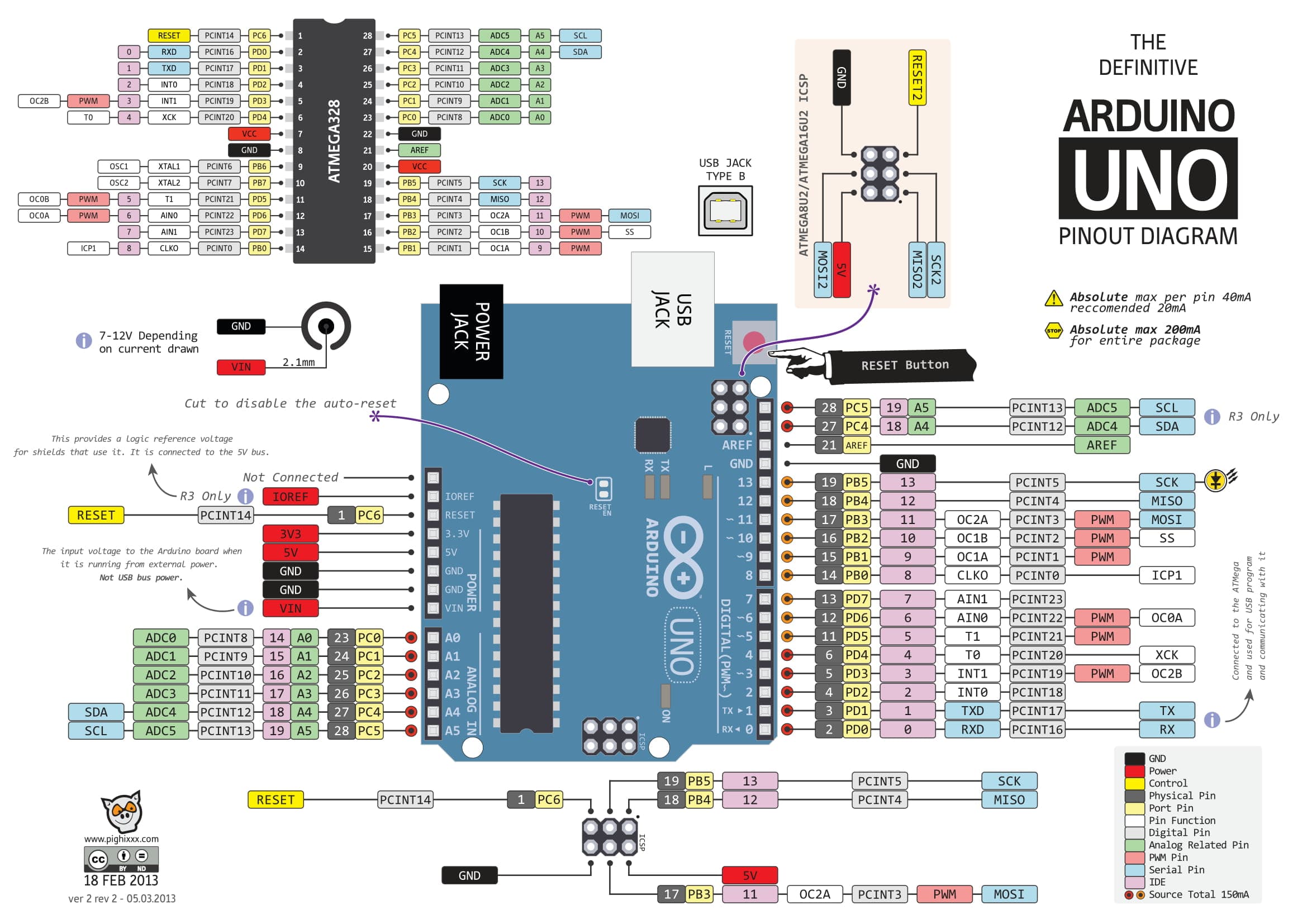 Download Arduino Uno Pinout PDF
Defining a pin as in input
based on the Arduino Uno pinout diagram we find that there are some pins that can be configured as an input, some can be an input to read analog values as well as digital values marked as (A0 - A7) and the other can only be used as digital marked (0 - 13).
Digital pins
In order to use any pin as a digital input or output you must specify it before reading from it or writing to it in order to make the microcontroller understand the direction of the pin.
Make Digital Pins As Input
there are two ways of defining an input
1st method : without internal pullups, for example pin 2 as input
pinMode(2, INPUT);
this sets the pin number two to work as an input pin. a small note about this method, incase the pin is set to be an input but nothing is connected to it out side, it would be floating an that will cause it to fluctuate between logic 0 and logic 1 and any external static charges can effect the reading value.
2nd method : with internal pullups, for example pin 2 as an input
pinMode(2, INPUT_PULLUP);
this method ties the pin to the supply voltage internally within the chip via an internal resistor so the default reading value is logic 1 unless an external signal pulls the signal low to logic 0, therefore when nothing is connected to the pin the value will not fluctuate like the previous method.
Reading Digital Input Value
reading a digital value on a digital input pin is done via the following command, for example we need to read the digital input pin 2.
digitalRead(2);
this command return a value of 0 or 1 which are boolean state values and also can be read as digital value too to resemble a number not a state like the boolean does.
Reading Analog Input Value
you can read the analog values directly without the need for defining it as an input by the following command for example I want to read an analog value from pin A0, I type
analogRead(A0);
This command returns and integer value between 0 - 1023 based on the Arduino Uno sampling resolution of 10 Bits
Make Digital Pins As Output
in order to make a digital pin work as an output you need to type the following command
pinMode(2, OUTPUT);
by this command the microcontroller understands that the direction of the pin is output therefore the pin throw out a value of (logic 1 = +5 volts) or (logic 0 = 0 volts) and cannot tolerate to take a value from and external signal source this might fry your microcontroller if you are not carful when connecting the pin and you configure it in the wrong way.
Writing Digital Output Value
Throwing out a login 1 on an output pin can be done via the following command for example pin number 2 gives a logic 1 = +5 volts
digitalWrite(2, HIGH);
Throwing out a login 0 on an output pin can be done via the following command for example pin number 2 gives a logic 0 = 0 volts
digitalWrite(2, LOW);
for further references on different kinds of commands for Arduino IDE C++ microcontroller language please visit the following link.
https://www.arduino.cc/reference/en/
Task 1 : Build A Circuit Using Arduino Uno Dev Board
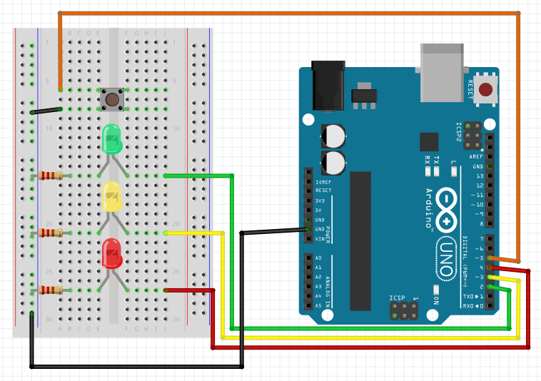
I planned to build a traffic light signal that the lighting sequence starts from red then moves to yellow then moves to green in a continuous manner without the button effecting it, this is to exercise defining pins as an output and controlling LEDs, illuminating them by introducing a logic level 1 on to them to light up and a logic level 0 to turn off. I connected the 3 LEDs on 3 different pins as shown in the diagram.
Start The Arduino IDE, and this is what you are going to see
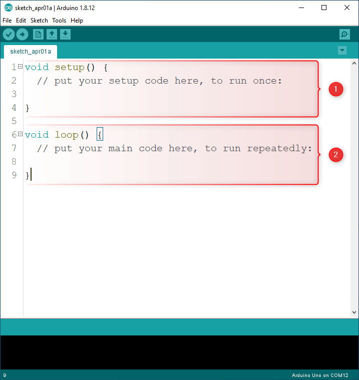
as you can see there is two ready maid functions and they are the basic building blocks of any Arduino program,
- setup function
- loop function
setup function : is the code block that will first run as soon as you power on the Arduino board or after a reset and it runs only once at the startup. therefore since it has this great feature I recommend to setup the pins here directly because we need to define their direction and the way they function only once.
- Digital I/O pin 2 -> RED Led (OUTPUT)
- Digital I/O pin 3 -> YELLOW Led (OUTPUT)
- Digital I/O pin 4 -> GREEN Led (OUTPUT)
- Digital I/O pin 5 <- BUTTON (INPUT)
loop function : is the code that will keep running looping up on it self, and this is where its perfect to write our code because the base of our programming to run a continuous process and to obey the flow we program it to do.
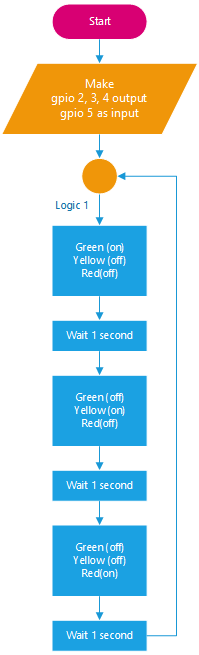
Traffic LED Lighting Without Button Press
The lighting order starts from red then yellow then green in a continuous manner. The flow chart of operations is as shown below
Flow Chart
Code
#define RED_LED     2
#define YELLOW_LED  3
#define GREEN_LED   4
#define BUTTON      5

void setup()
{
  Serial.begin(9600);
  pinMode(RED_LED, OUTPUT);
  pinMode(YELLOW_LED, OUTPUT);
  pinMode(GREEN_LED, OUTPUT);
  pinMode(BUTTON, INPUT_PULLUP);
}

void loop()
{
  digitalWrite(RED_LED, HIGH);
  digitalWrite(YELLOW_LED, LOW);
  digitalWrite(GREEN_LED, LOW);
  Serial.println("Stop");
  delay(1000);
  digitalWrite(RED_LED, LOW);
  digitalWrite(YELLOW_LED, HIGH);
  digitalWrite(GREEN_LED, LOW);
  Serial.println("Ready");
  delay(1000);
  digitalWrite(RED_LED, LOW);
  digitalWrite(YELLOW_LED, LOW);
  digitalWrite(GREEN_LED, HIGH);
  Serial.println("Go");
  delay(1000);
}
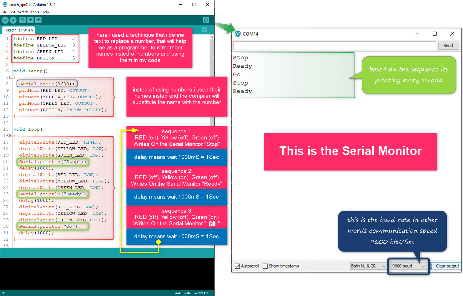
Result
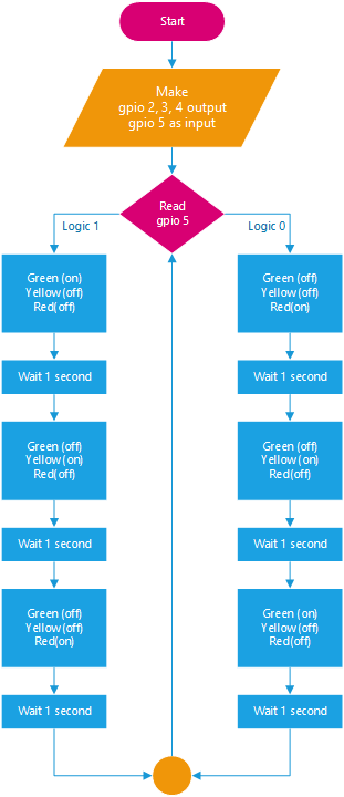
Traffic LED Lighting Order Based On Button Press
in this example I created two routines (procedures) one same the as previous example, and the other moves the light sequence the opposite way if the button is clicked
Flow Chart
Code
#define RED_LED     2
#define YELLOW_LED  3
#define GREEN_LED   4
#define BUTTON      5

void setup() {
  Serial.begin(9600);
  pinMode(RED_LED, OUTPUT);
  pinMode(YELLOW_LED, OUTPUT);
  pinMode(GREEN_LED, OUTPUT);
  pinMode(BUTTON, INPUT_PULLUP);
}

void loop() {

  if(digitalRead(BUTTON) == LOW) {
    fw_run_led();
  } else {
    bw_run_led();
  }

}

void fw_run_led() {
  digitalWrite(RED_LED, HIGH);
  digitalWrite(YELLOW_LED, LOW);
  digitalWrite(GREEN_LED, LOW);
  Serial.println("Stop");
  delay(1000);
  digitalWrite(RED_LED, LOW);
  digitalWrite(YELLOW_LED, HIGH);
  digitalWrite(GREEN_LED, LOW);
  Serial.println("Ready");
  delay(1000);
  digitalWrite(RED_LED, LOW);
  digitalWrite(YELLOW_LED, LOW);
  digitalWrite(GREEN_LED, HIGH);
  Serial.println("Go");
  delay(1000);
}

void bw_run_led() {
  digitalWrite(RED_LED, LOW);
  digitalWrite(YELLOW_LED, LOW);
  digitalWrite(GREEN_LED, HIGH);
  Serial.println("Stop");
  delay(1000);
  digitalWrite(RED_LED, LOW);
  digitalWrite(YELLOW_LED, HIGH);
  digitalWrite(GREEN_LED, LOW);
  Serial.println("Ready");
  delay(1000);
  digitalWrite(RED_LED, HIGH);
  digitalWrite(YELLOW_LED, LOW);
  digitalWrite(GREEN_LED, LOW);
  Serial.println("Go");
  delay(1000);
}
Result
Programming My Own ATTINEY84 Board
I have done this previously in electronic design week please reffer to the following link http://fabacademy.org/2020/labs/bahrain/students/ghassan-yousif/assignments/week07/#connecting-icsp-powering-up-the-circuit
Task 2 : Platform I/O plugin on Atom or Visual Studio Code
Task two can be found on the nest assignment since it include inputs so please click on the following Link