Computer Controlled Machining
This week we were suggested to test run out, alignment, speeds, feeds, and toolpaths for our machine for the group assignment. For the individual assignment, we had to make something "Big".
GETTING STARTED WITH CNC WOOD ROUTER
I googled and search for this machine and found this link gives the best detail about this machine.
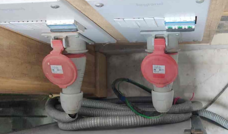
First we have to start from here to turn on the Machine. The left side switch is to give power supply to the machine and the right side switch is to give the power to the vacuum pump.
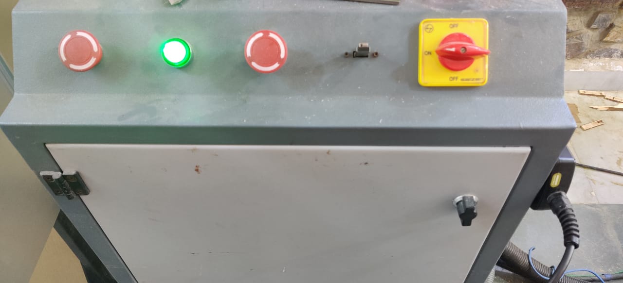
The front controls are shown here. The left-most emergency switch is to turn the spindle off. The rightmost switch is to turn the machine on. The middle emergency switch is to stop the machine altogether and this is the one we need to press in case of an emergency. To turn the machine on PRESS the green light switch. From right the second slot is USB slot.
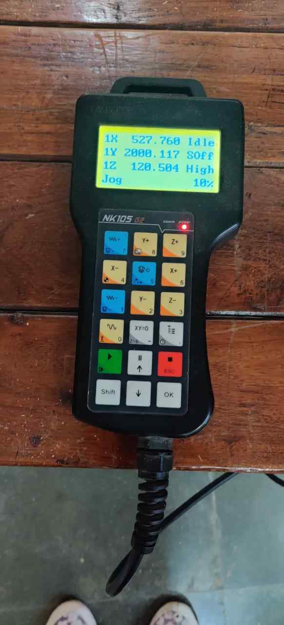
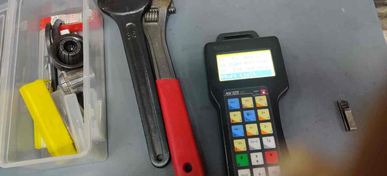
This is showing Teach pendant to control the CNC Wood Router and accessories like Collet, Drill, and Wrench to hold the workpiece using Clamps
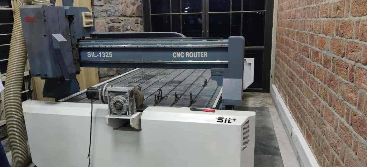
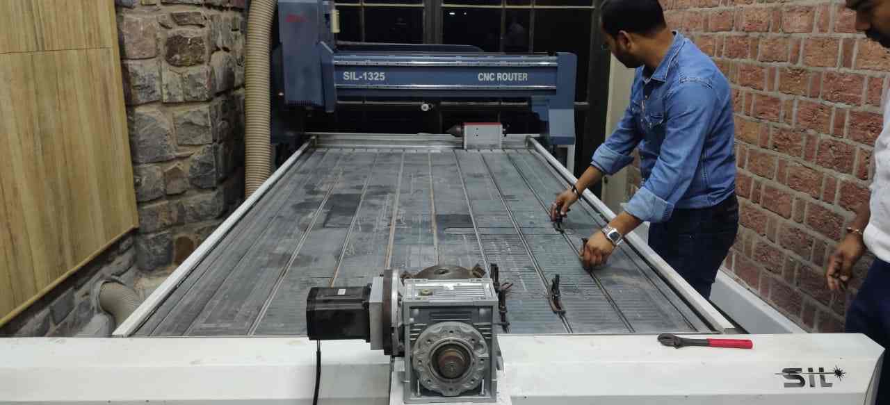
This is a big machine SIL 1325 CNC wood router fits for assignment "Make something Big"
Homing
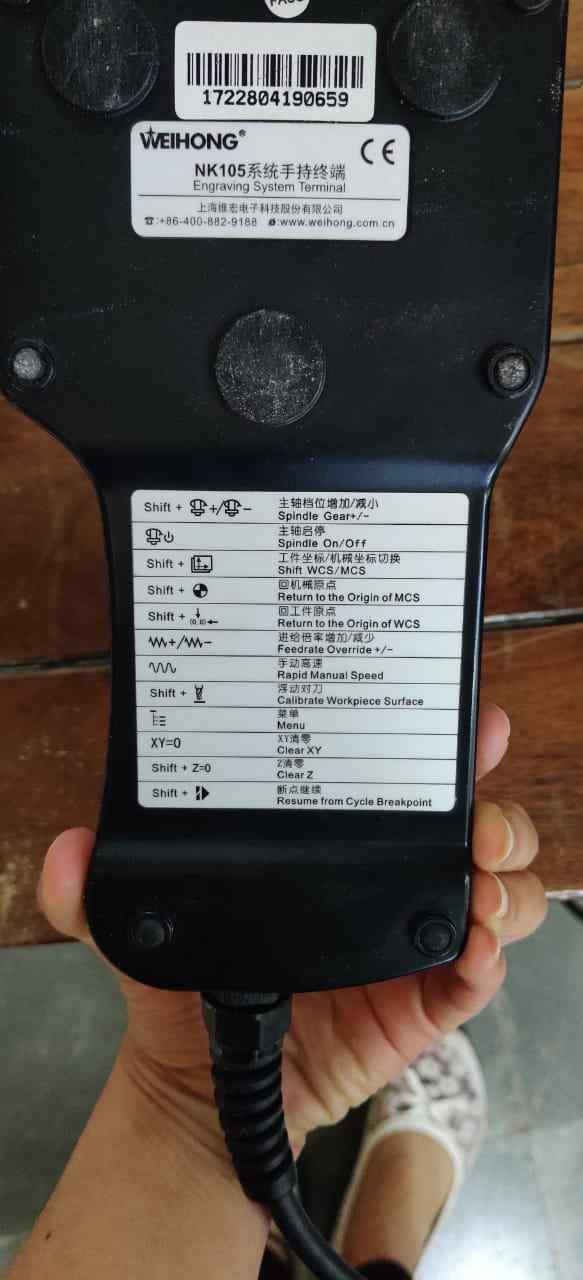
We press Shift and 4 together to bring the CNC router to home position ie return to the machine MCS(machine coordinate system). It is important to home the machine first through which the machine knows its reference points. After this we can manually bring the tool close to the bottom left corner by pressing the X and Y keys. Jog option is used for faster operation if required.Setting the origin
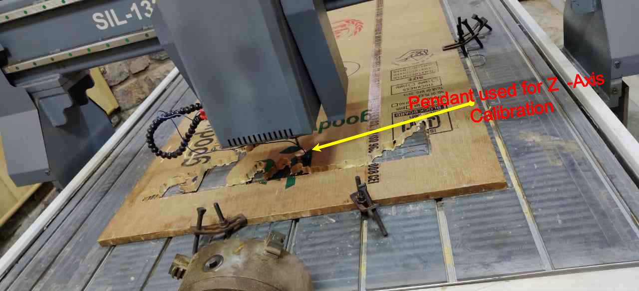
Next we have to set our origin for the workpiece. The origin is set on the bottom right corner as the reference. We set the button “XY=0” to set the origin for X and Y. Next we have to calibrate the Z-axis. We have to put the metal cylindrical block below the CNC bit and press Shift and 0 together for Z-axis Calibration. After calibration, we need to press “Z=0” to set up our Z position.When the tool touches the surface of the cylindrical pendant it automatically detects the z coordinate as 11mm because the height of the cylindrical pendant is 11mm and which is placed on CNC wood router bed so for that we take it as z- home position.
Our Instructor Rahul Gautam told us how to operate this machine.
One Test file was cut on it by our instructor Mr. Rahul Gautam
Group Assignment
In group assignment we decided to cut lines on different speed and feed rates and also cut a square of 50mm on outside, inside, and on profile.
The first step was to download Aspire as this is paid software and so we downloaded the crack version and installed Aspire 8.0 version. Then pulkit from our group made some lines on Aspire sketch tools and then after creating toolpath it is exported in CAM tech RMS(mm)(*.cnc). we just give tests run on different speeds to different lines. The step by step process has been shown in an individual assignment.
TEST CUT 1
These are the listed speed and Rpm setting on which the cuts take place:
- yellow--3S 50%
- Red--4S 50%
- White--5S 50%
- Blue--3S 40%
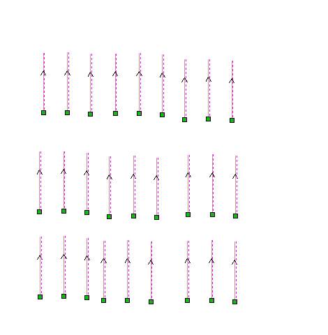
2D Toolpath on Aspire
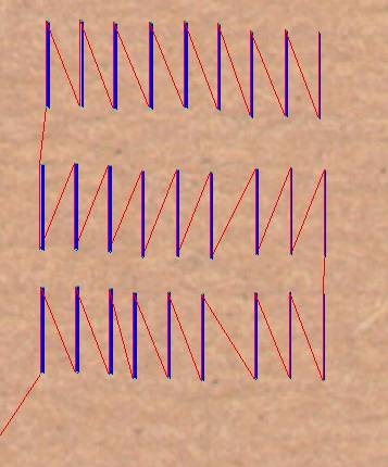
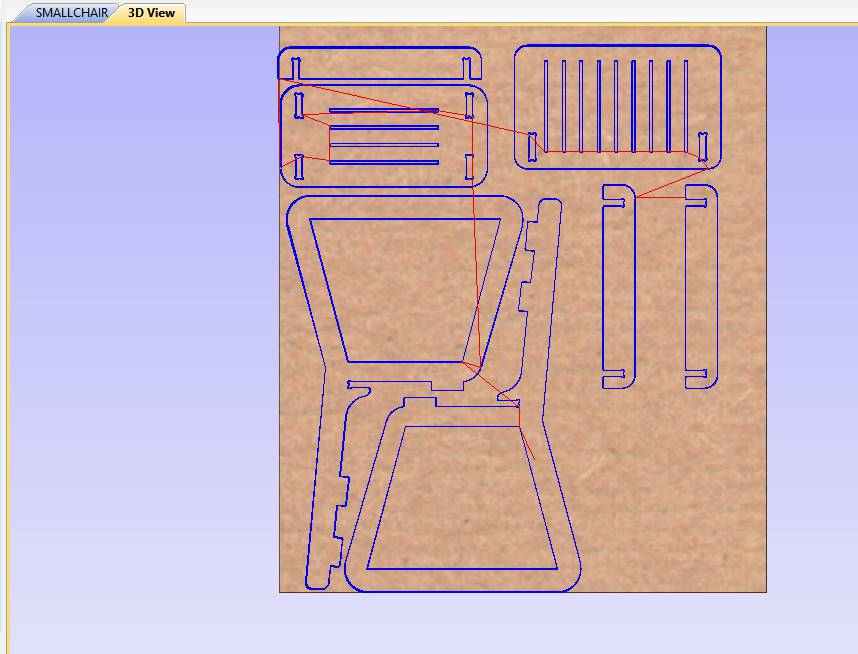
3D View of Toolpath on Aspire
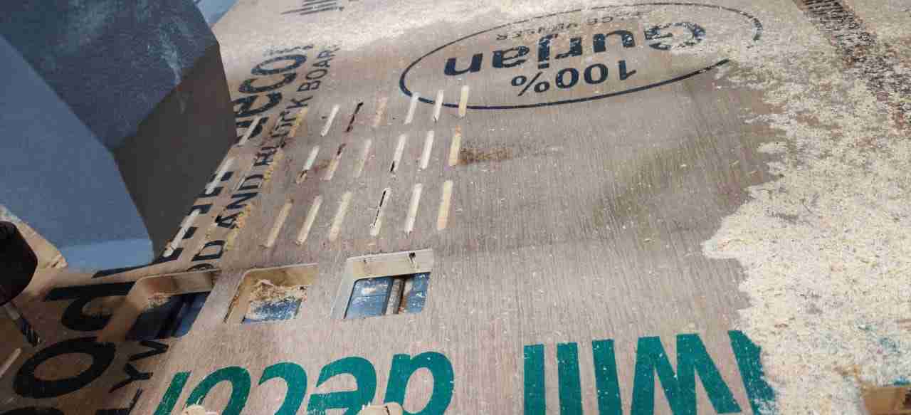
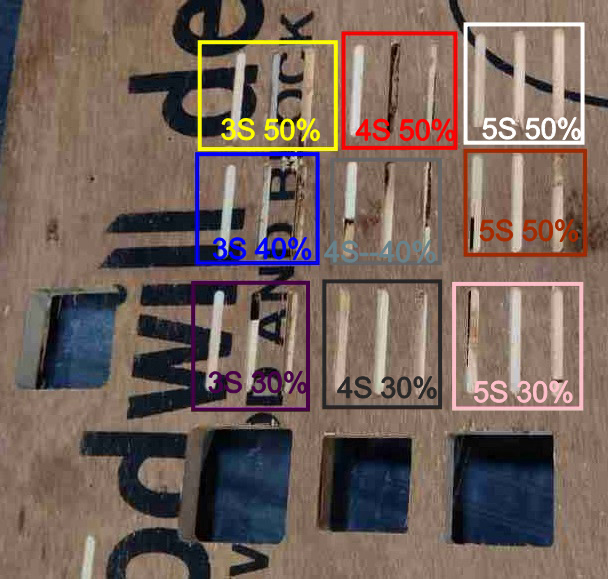
This test was done to check the surface finish at various speeds and rpm. So the best we get at 3s Speed and 30% rpm, at these parameters the noise is less and it is safer to work on this speed as at higher speed there will be a chance of an accident if tool bit break. This test was done to check the surface finish at various speeds and rpm.
Test Cut 2
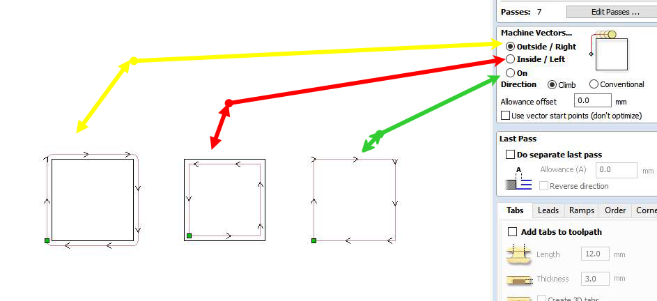
The Square blocks of 50mm dimensions have been cut in three machine vectors, on the periphery, outside the periphery, and inside the periphery means the tool moves on rectangle outside the rectangle and inside a rectangle. As the diameter of the tool was 6mm, in case of outside the 6mm extra material has removed. In case of inside the dimension of rectangular cross-section decrease by 6mm on both side and 50 mm square come out to be approximately 37 mm including kerf. We get the exact size in the outside profile.

These are toolpath in 3D-View
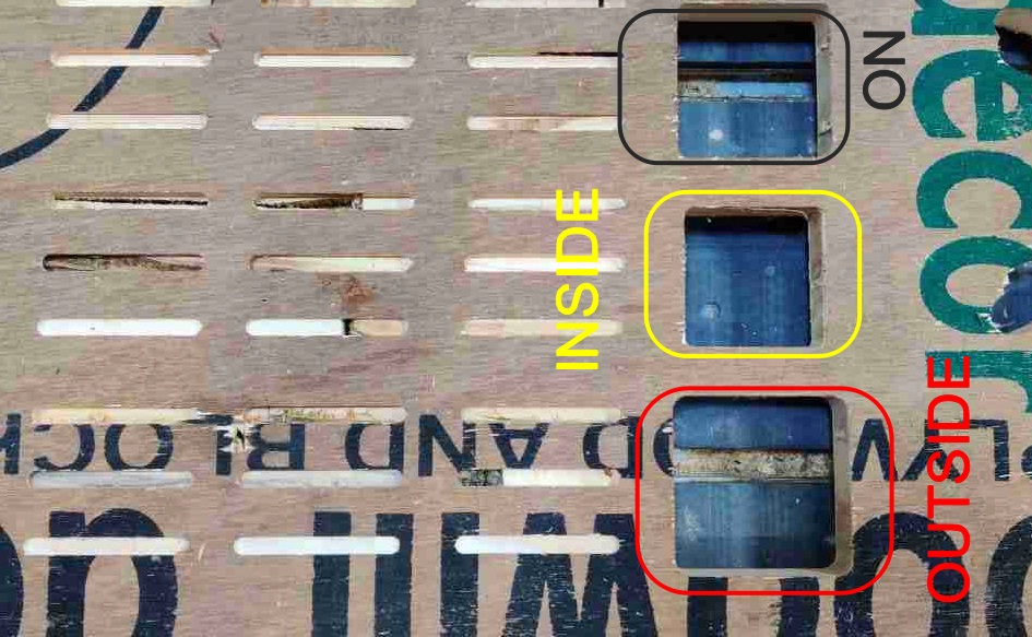
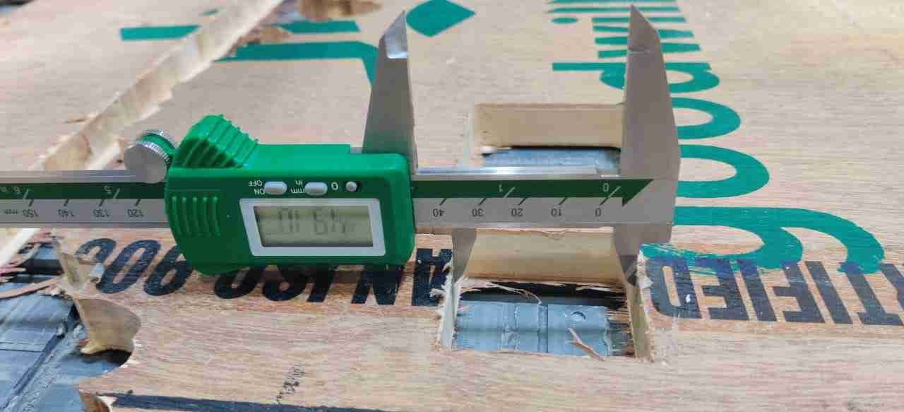
Actual Dimension came out to be for three configuration are:
- (i) The Rectangle for IN path came out to be 50x50mm exact and the inner portion of rectangle was 37.4mmx37.5mm.
- (ii) The Rectangle for OUT path which came out to be is 62.6mmx62mm and the inner rectangle is 50mmx50mm.
- (iii) The rectangle for ON path came out to be 55.5mmx56mm and the rectangle came out to be 46mmx46mm.
TEST CUT 3
In this test we want to check the joint fit in a particular slot. For the motion of tool inside of the slot and outside of the block. They both fit exactly into each other.
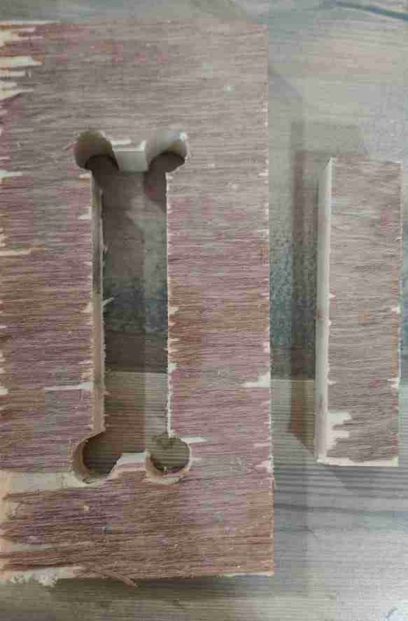
It is the rectangular block cut with a manual dogbone designed to aspire to check joint clearance.
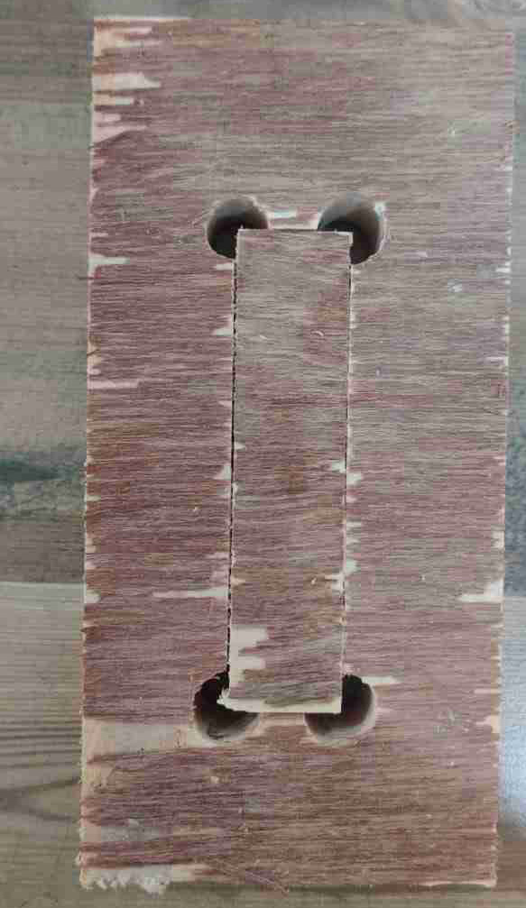
The rectangle block of exact dimensions fits into it.
Note: According to Test Cut 3 as with the help of dogbone and in 19mm thick wood can fits into 19mm slots when it cuts slots with inside tool motion and block with outside tool motion.
DESIGNING ON SOLID EDGE
I used Solid edge St-9 CAD tool for designing a chair.
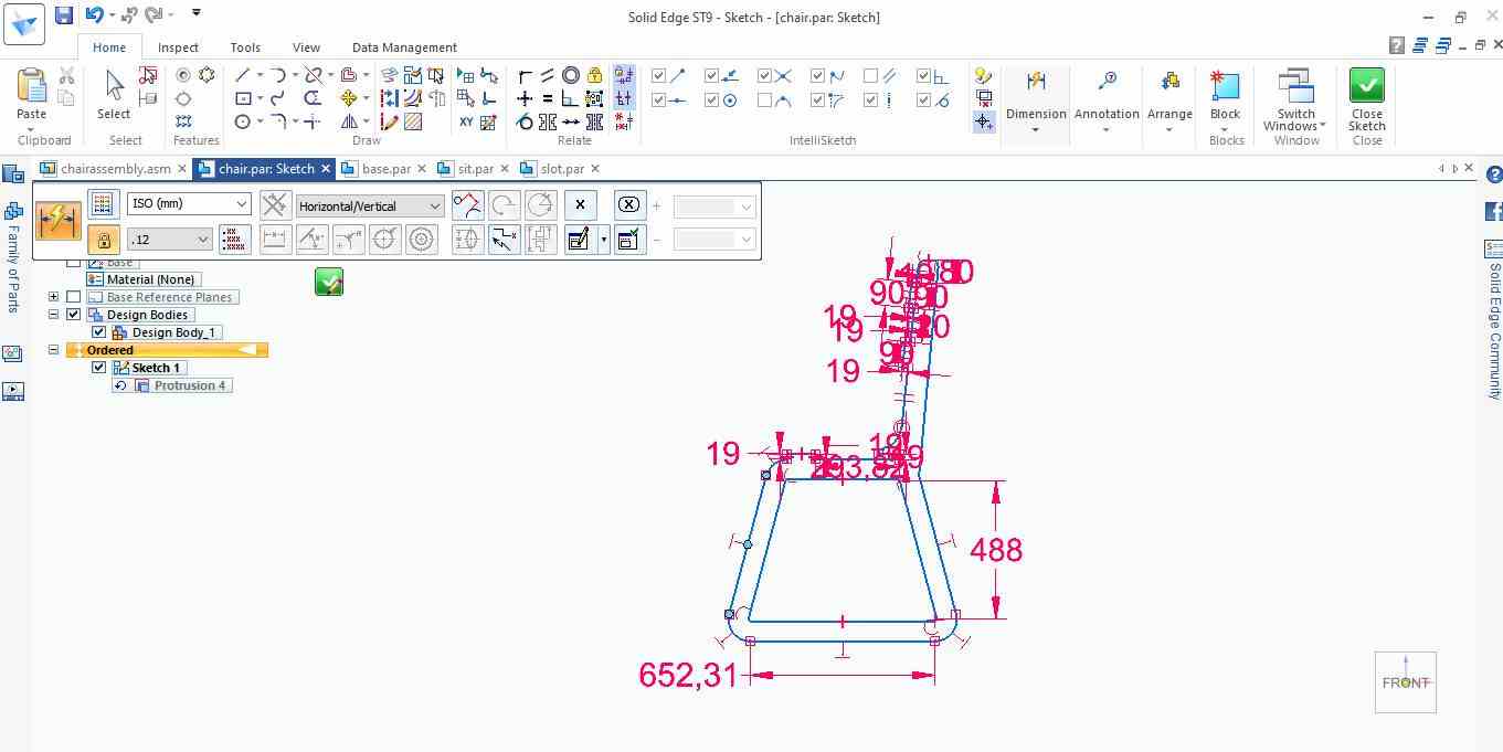
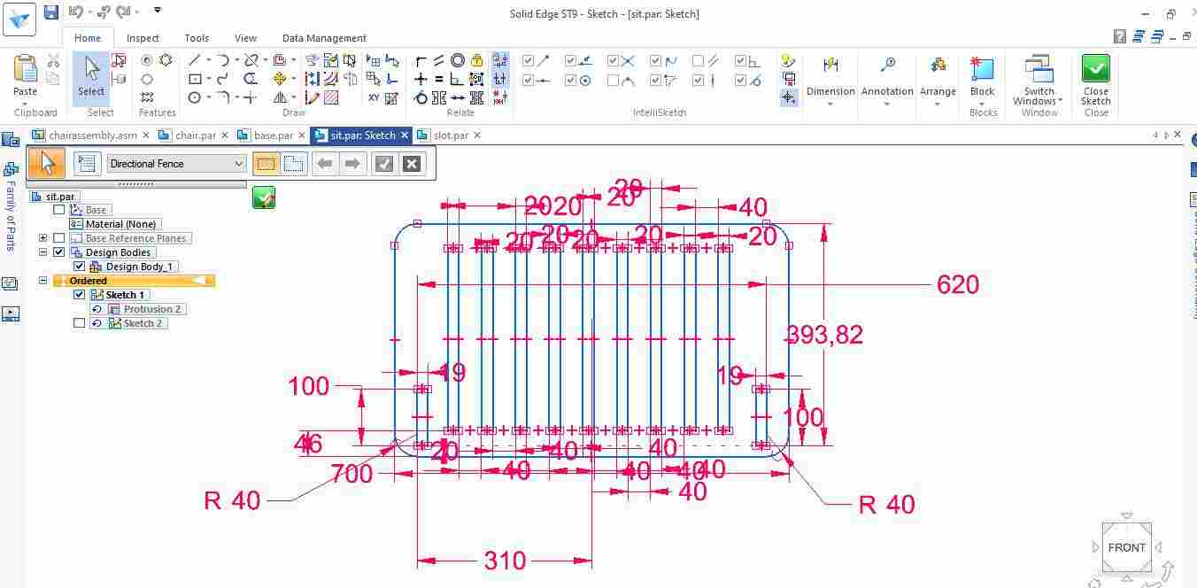
This is the sketch showing cross section of chair.
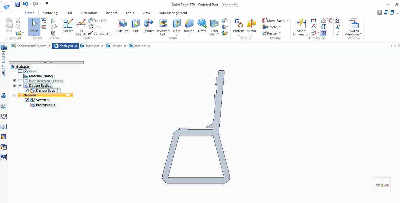
This is the image showing extrude command applied on it.
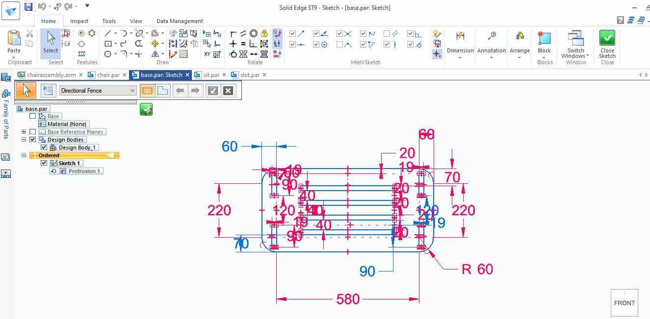
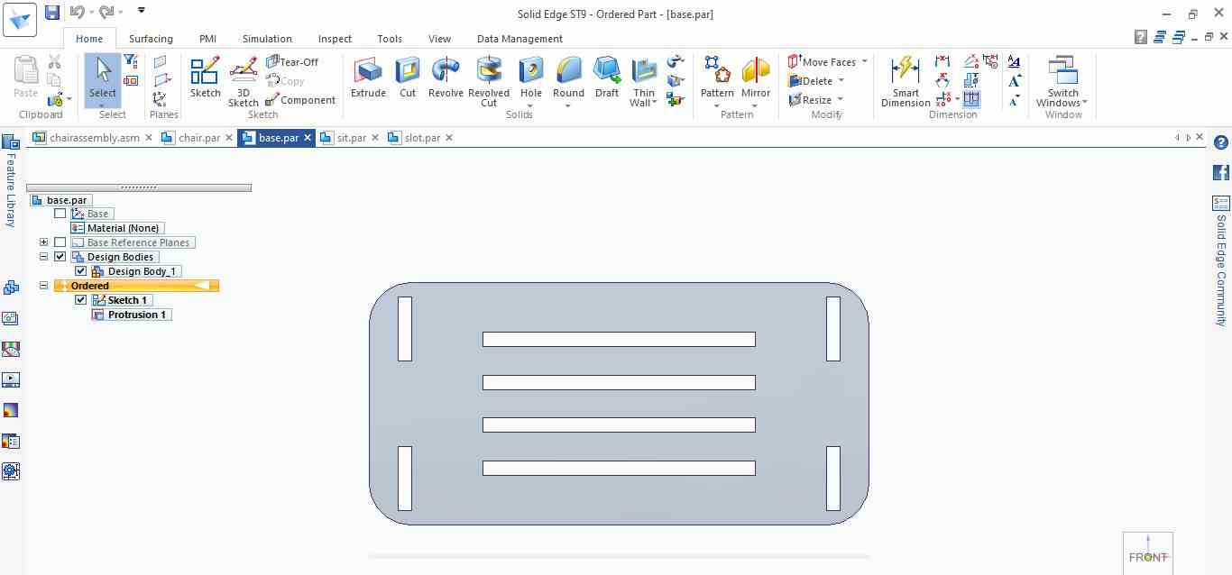
This is the part to support the back .
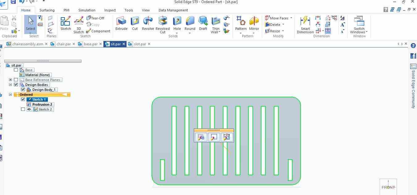
This part is designed to sit upon.
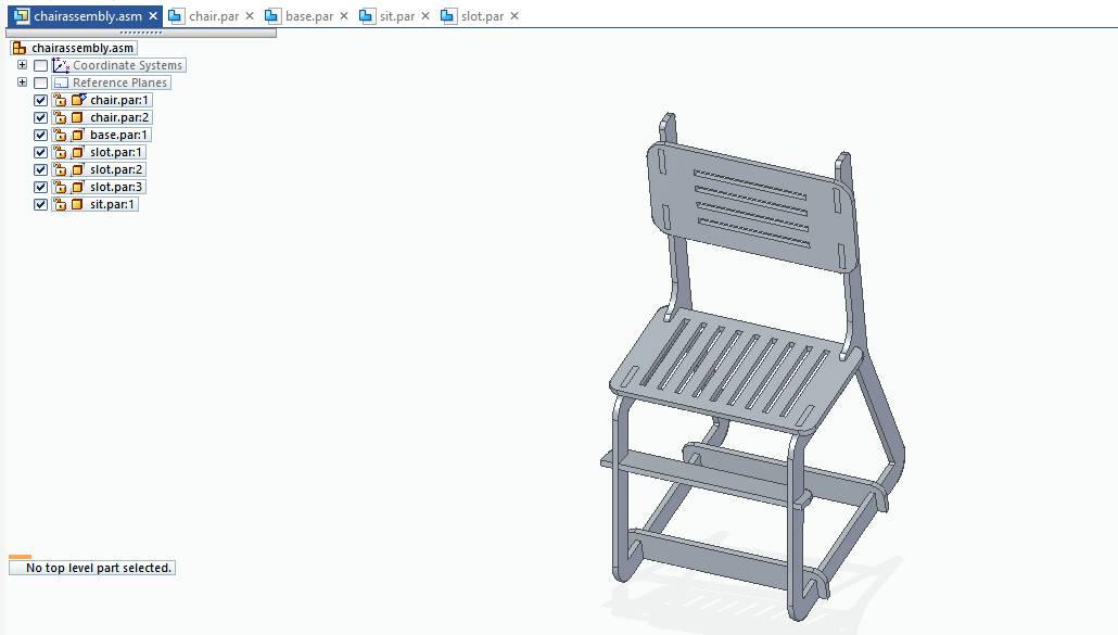
Here all the parts are assembled by using assembly constraints. This is the whole Assembly of Chair.
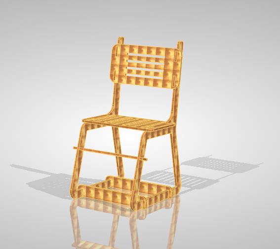
Some rendering on it.
Note:
While designing I dint need to give any clearance as I used the dogbone fillet on aspire itself and I gave 19mm width slot according to test cut 3.The only plyboard available with us was of 19mm.So the design was according to 19mm thickness.
Exporting DXF
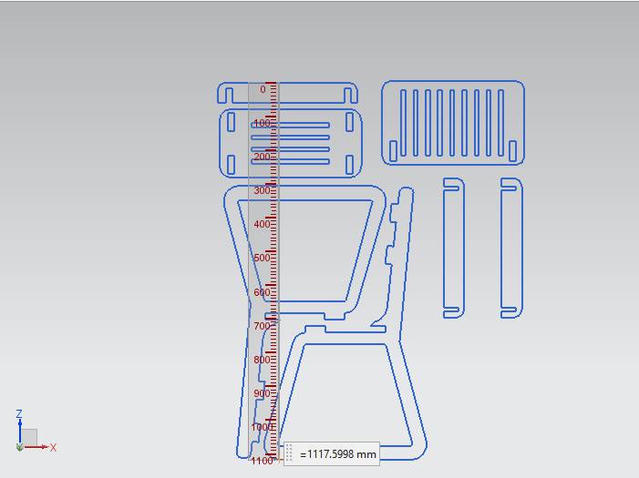
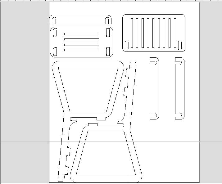
Its time to export the dxf , I add all th parts together in order to align them in a way that while cuting minimum amount of wastage will be there. So I exported it as .dxf file.
Prototype on Laser Cutter
Before going on Big machine it is necessary to check design by making a prototype on the Laser Cutting machine. So I used cardboard to cut the design. Settings were same , did in laser cutting week.
For this week kerf of cardboard is not that much important it fitted into slots of cardboard without considering it as cardboard is flexible enough.
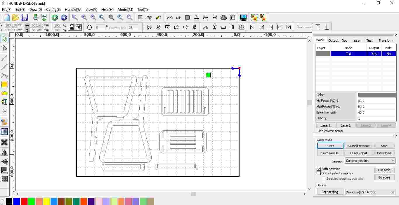
The setting were Max power : 60 , Min power : 60 , Speed ; 40%
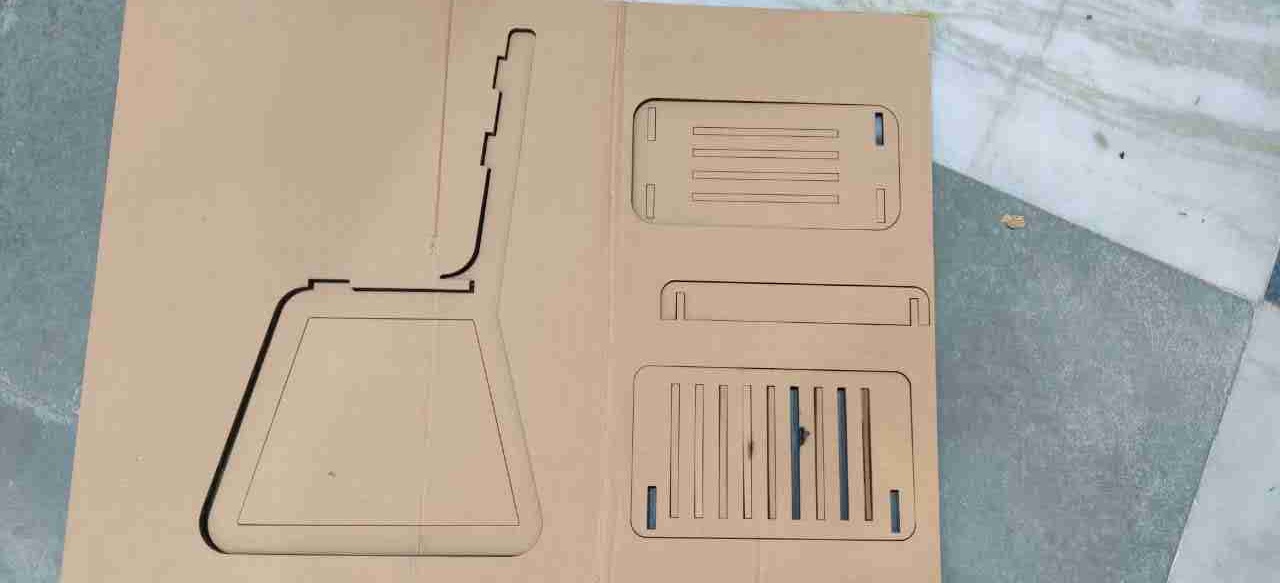
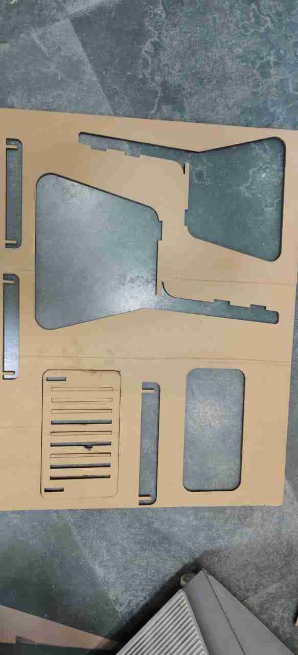
This is showing the prototype of chair on cardboard.
The prototype comes well the one thing I missed was while scaling the whole model in RD-works I reduced the size to get the slot size as exactly as my cardboard thickness is used. So I calculated like my actual slot size is 19mm and the cardboard I used was of 4mm thickness.So I need to scale down it 80 percent. One part I cut again due to limitation of cardboard as it burns in between for that I reduced the size to 70%. The leg of the chair at left is little looking larger but somehow fits in..
WORK ON ASPIRE
I tried trial version first of this software and as trial version does not give access to export the codes for machining. I went for a crack version of Aspire.
STEPS
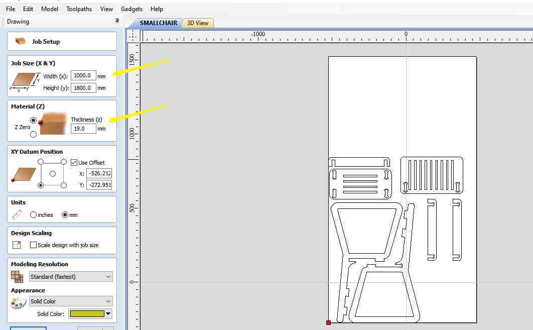
1. First Click on Job setup, so that the size of wood be specified in it. In my case, it was 1000mm*1800mm and thickness=19mm
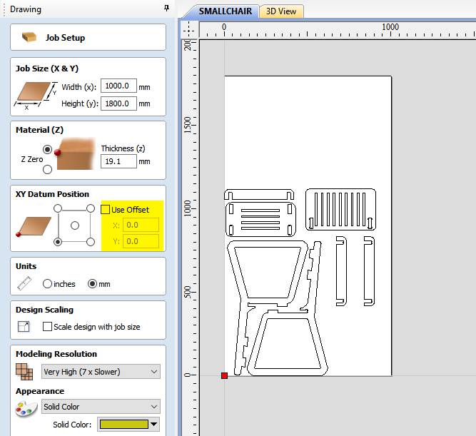
2. Select the datum, I select the bottom left corner like this the home position of my machine. And also select the offset as 0,0 otherwise the machine will start from that position only.
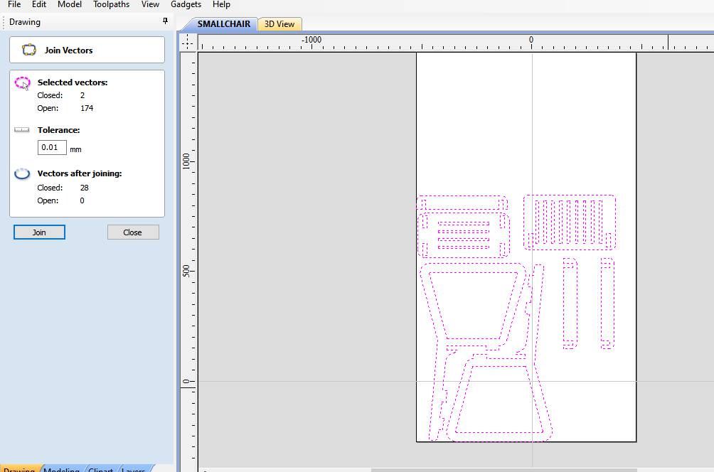
3. Next is to Join the vectors unless the tool path will not create for the profile.
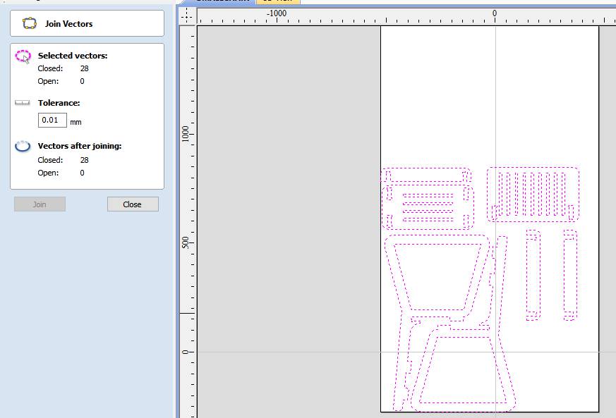
4. By selecting the whole profile, click on join vectors option. Click on Join to get zero open vectors. As well as by right click on profile delete the duplicate vectors.
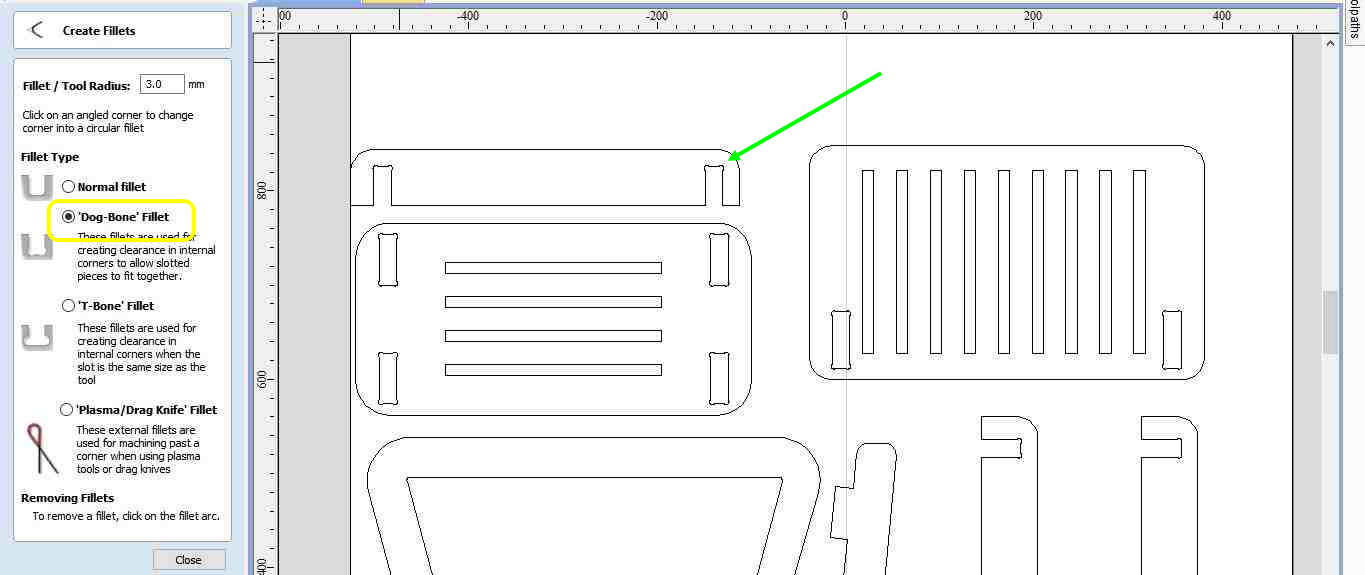
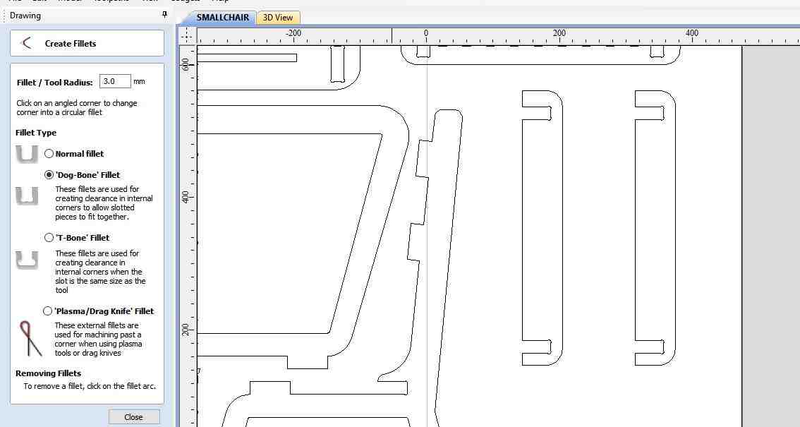
5. Dogbone option is there to create a fillet, It is necessary to provide dogbone as done earlier it gives the exact fit as tool dia volume cut outside corners.
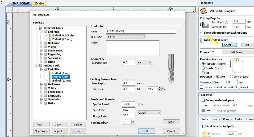
6. Now click on tool path, Give cutting depth, select tool. I select a 6mm endmill that was available in the fab lab.
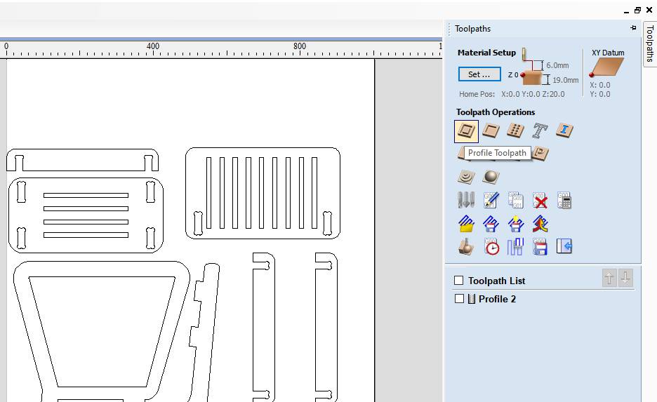
7. Click on toolpath Opertion.
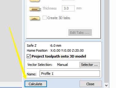
8. Click on calculate.
9. These blue lines showing the tool path generated.
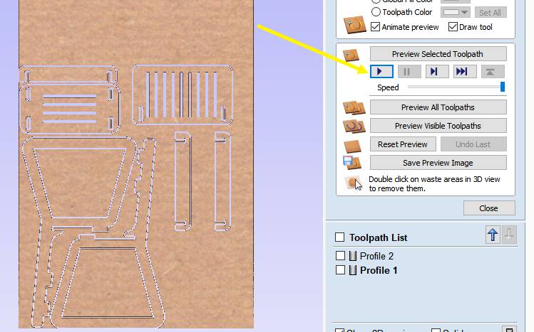
10. To preview how the tool will move and cut the workpiece, Click on the preview tool path.
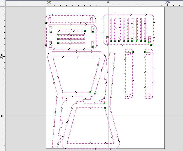
11. Profile of toolpath. Arrows show the direction of the motion of the tool.
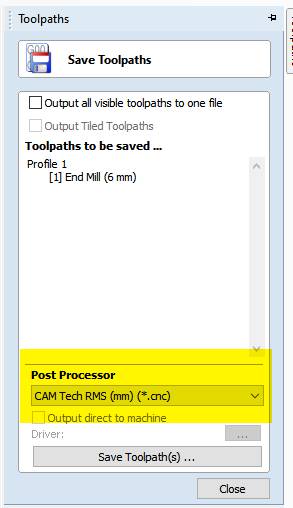
12. Last step to export the tool path in format, according to the CNC wood router. I exported in CAM tech RMS(mm)(*.cnc)
Cutting on CNC Wood Router:
After exporting the (.cnc) file save it into Pendrive and insert the Pendrive in the slot provided in the controller of Wood router. Clamp the workpiece in a way that it does not collide with the tool in between the motion of the tool.
The spped and feed were considered which we got in test cut 1 because of higher surface finish.
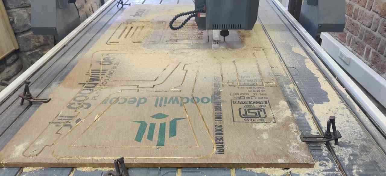
Set the machine origin in the same way as explained earlier and load the file and click ok to run the machine. Above is the image showing cutting in process.
At this feed the chances of misalignment of workpiece while cutting is higher so we chnage the feed from 30 to 20% which actualy increased the time of machining.But was safe to work on this setting.
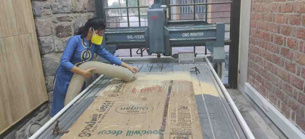
After the machining completed, it is necessary to clean the table and workpiece with a vacuum pump. In this image, I am doing the same.
Assembly
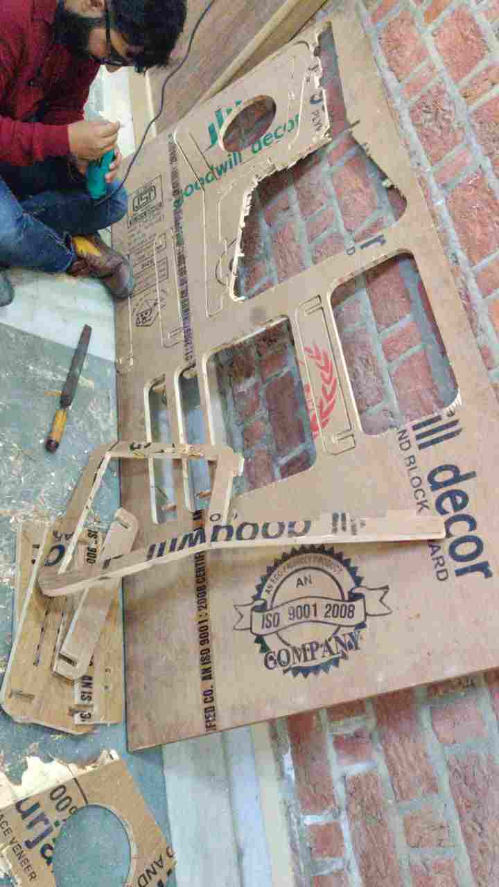
After cutting I got to know that the board thickness is not even, It is varying at one point to other and so the cut parts did not come easily. So my fab mate Pulkit help me to remove all the parts of the chair from the board.He also cut one circular part manually with a machine in between legs of my chair. We even use the drill to remove it.
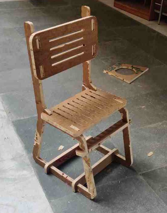
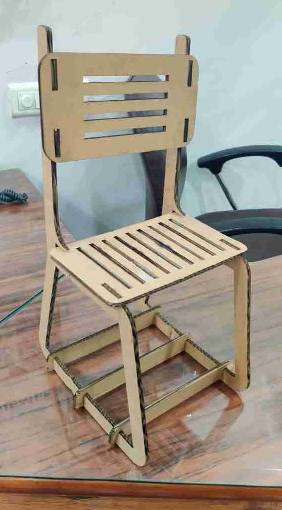
This is the assembled chair.
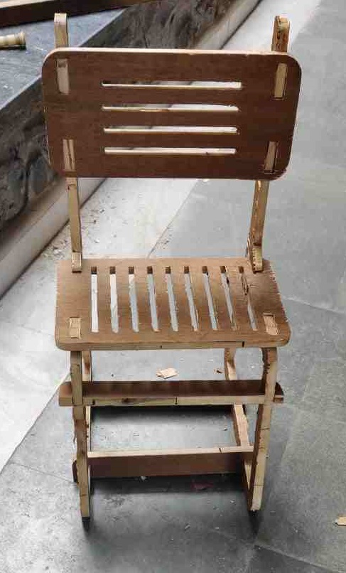
The results was so much satisfying.
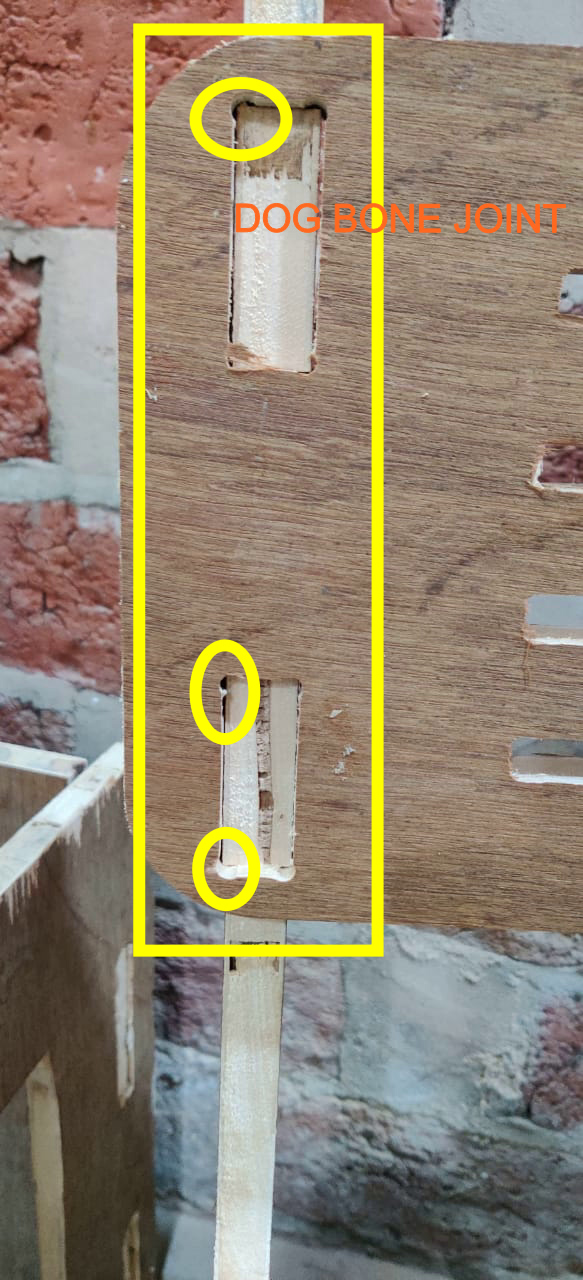
This is the dogbone joint of 3mm circle radius.
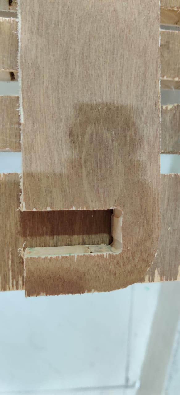
Dogbone Joint on attachment
As the wood used was plyboard and it wasnot that of good quality.Basically made of core of softwood stripes that are glued together.After cutting the inner layers tend to come out of outer layers which stack them together and When I fixed the plyboard in the slots I used hammer to fit into the slots,plyboard did not have that strength at some places it just collapse into pieces.I used fevicol and sawdust mixture to fix it.Rest it for a night to dry.
The resulted assembly could be better if wooden used will be plywood or Medium Density Board


This is me giving hero shot on chair.
Design Files
CNC WOOD ROUTER FILE
Experience and Isues Faced
While making chair on CNC wood router, I felt all of the time you have to be with CNC router as in my case the clamps become loose as when tool cuts the part and come out it exert force and if the clamping is not proper it made the whole sheet to move in the desired direction. The second thing was the uneven width of plywood made the depth of cut not to be proper at every point. So I manually remove till 4mm of material from the base where there was no clamping. As it lifts up there.