OUTPUT DEVICES
#Assignment
individual assignment:
group assignment:
What are Output Devices
Output devices in electronic systems transfer energy from the electrical energy that has been processed to another kind of energy, often light, sound or movement (kinetic). Output devices can be digital or analogue. Devices which perform an “Output” function are generally called Actuators
What is Servo Motor
A servo motor is an electrical device which can push or rotate an object with great precision. If you want to rotate and object at some specific angles or distance, then you use servo motor. It is just made up of simple motor which run through servo mechanism. If motor is used is DC powered then it is called DC servo motor, and if it is AC powered motor then it is called AC servo motor. We can get a very high torque servo motor in a small and light weight packages. Due to these features they are being used in many applications like toy car, RC helicopters and planes, Robotics, Machine etc.
Working principle of Servo Motors
A servo consists of a Motor (DC or AC), a potentiometer, gear assembly and a controlling circuit. First of all we use gear assembly to reduce RPM and to increase torque of motor. Say at initial position of servo motor shaft, the position of the potentiometer knob is such that there is no electrical signal generated at the output port of the potentiometer. Now an electrical signal is given to another input terminal of the error detector amplifier. Now difference between these two signals, one comes from potentiometer and another comes from other source, will be processed in feedback mechanism and output will be provided in term of error signal. This error signal acts as the input for motor and motor starts rotating. Now motor shaft is connected with potentiometer and as motor rotates so the potentiometer and it will generate a signal. So as the potentiometer’s angular position changes, its output feedback signal changes. After sometime the position of potentiometer reaches at a position that the output of potentiometer is same as external signal provided. At this condition, there will be no output signal from the amplifier to the motor input as there is no difference between external applied signal and the signal generated at potentiometer, and in this situation motor stops rotating.
Controlling Servo Motor:
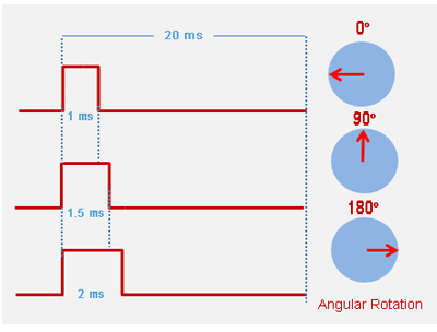
All motors have three wires coming out of them. Out of which two will be used for Supply (positive and negative) and one will be used for the signal that is to be sent from the MCU. Servo motor is controlled by PWM (Pulse with Modulation) which is provided by the control wires. There is a minimum pulse, a maximum pulse and a repetition rate. Servo motor can turn 90 degree from either direction form its neutral position. The servo motor expects to see a pulse every 20 milliseconds (ms) and the length of the pulse will determine how far the motor turns. For example, a 1.5ms pulse will make the motor turn to the 90° position, such as if pulse is shorter than 1.5ms shaft moves to 0° and if it is longer than 1.5ms than it will turn the servo to 180°. Servo motor works on PWM (Pulse width modulation) principle, means its angle of rotation is controlled by the duration of applied pulse to its Control PIN. Basically servo motor is made up of DC motor which is controlled by a variable resistor (potentiometer) and some gears. High speed force of DC motor is converted into torque by Gears. We know that WORK= FORCE X DISTANCE, in DC motor Force is less and distance (speed) is high and in Servo, force is High and distance is less. Potentiometer is connected to the output shaft of the Servo, to calculate the angle and stop the DC motor on required angle.
Source Servo Motor
programming for servoSERVO MOTOR WITH ATTINY 45
Due to COVID 19 we were supposed to do output device on Tinkercad as we dont have lab Access.Below are some the examples performed by me.
CODE
  void setup() {
  pinMode(PB1, OUTPUT);

}

void loop()
{
   // keep sending 0 position for about 400ms
for(int i = 0; i< 20; ++i) {
  digitalWrite(PB1, HIGH);
  delayMicroseconds(1000);
  digitalWrite(PB1, LOW);
  delay(19);
}

// keep sending second position for about 400ms
for(int i = 0; i< 20; ++i) {
  digitalWrite(PB1, HIGH);
  delayMicroseconds(2000);
  digitalWrite(PB1, LOW);
  delay(19);
}
}
SERVO MOTOR WITH LDR AND ARDUINO
CODE
  //include the servo library

  #include "Servo.h"

  //create a servo object called servo1
  Servo servo1;

  void setup() { // put your setup code here, to run once:

  // set the servo pin, pin 1, as an servo output pin
    servo1.attach(1); }

  void loop() { // put your main code here, to run repeatedly:

  int lightValue = analogRead(3);

  // map the light readings to the angle possible by the servo motor
    lightValue = map (lightValue, 0, 1023, 0, 180);

  // control the servo motor based on the light value read, adjust linearly by angles
    servo1.write (lightValue);
  }
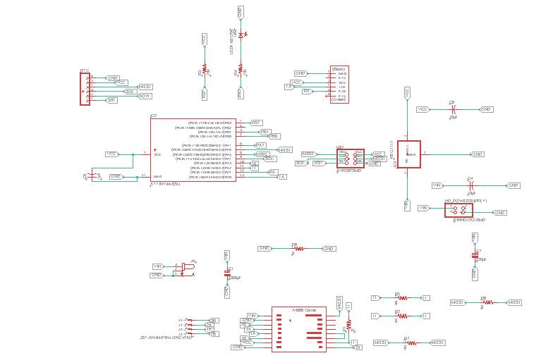
SERVO MOTOR WITH LDR AND ATTINY 45
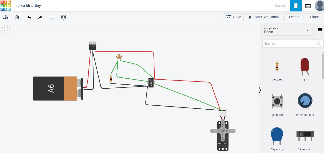
These are the connections which I made to connect LDR with Servo motor.In this way I can made my eagle schematic for both.
WHAT ARE NEOPIXEL LED
These are individually addressable LEDs all housed on a string that can be controlled from a single pin on a microcontroller. This means one pin can control all of the LEDs colors and which LEDs are on at any given time. When compared to a normal RGB LED you'll notice that we need 3 pins to control the RedGreen and Blue value and all LEDs have to remain on or off. So as you can see using individually addressable can help create some cool effects.
Source How neopixel work
Here you can find the library for arduino ide programming
NEOPIXEL WITH ATTINY 45
CODE
// NeoPixel Ring simple sketch (c) 2013 Shae Erisson
// released under the GPLv3 license to match the rest of the AdaFruit NeoPixel library
#include "Adafruit_NeoPixel.h"
#ifdef __AVR__
#include "avr/power.h"
#endif
// Which pin on the Arduino is connected to the NeoPixels?
// On a Trinket or Gemma we suggest changing this to 1
#define PIN 2
// How many NeoPixels are attached to the Arduino?
#define NUMPIXELS 6
// When we setup the NeoPixel library, we tell it how many pixels, and which pin to use to send signals.
// Note that for older NeoPixel strips you might need to change the third parameter--see the strandtest
// example for more information on possible values.
Adafruit_NeoPixel pixels = Adafruit_NeoPixel(NUMPIXELS, PIN, NEO_GRB + NEO_KHZ800);
int delayval = 500; // delay for half a second
void setup() {
// This is for Trinket 5V 16MHz, you can remove these three lines if you are not using a Trinket
#if defined (__AVR_ATtiny45__)
if (F_CPU == 16000000) clock_prescale_set(clock_div_1);
#endif
// End of trinket special code
pixels.begin(); // This initializes the NeoPixel library.
}
void loop() {
// For a set of NeoPixels the first NeoPixel is 0, second is 1, all the way up to the count of pixels minus one.
for(int i=0;i< NUMPIXELS;i++){
// pixels.Color takes RGB values, from 0,0,0 up to 255,255,255
pixels.setPixelColor(i, pixels.Color(0,150,0)); // Moderately bright green color.
pixels.setPixelColor(i, pixels.Color(225,225,0));
pixels.show(); // This sends the updated pixel color to the hardware.
delay(delayval); // Delay for a period of time (in milliseconds).
}
}
ARDUINO WITH HOBBY MOTOR
CODE
void setup(){
pinMode(6, OUTPUT);
pinMode(5, OUTPUT);
pinMode(4, OUTPUT);
pinMode(3, OUTPUT);
}
void loop (){
digitalWrite(6, HIGH);
digitalWrite(5, LOW);
digitalWrite(4, HIGH);
digitalWrite(3, LOW);
delay(1000);//1000ms=1 sec
}
ARDUINO WITH DC MOTOR
const int IN1 = 4;
const int IN2 = 7;
const int EN1 = 5;
void setup()

{
   pinMode(IN1,OUTPUT);

   pinMode(IN2,OUTPUT);
   pinMode(EN1,OUTPUT);
}
void loop()
{
    digitalWrite(IN1,HIGH);  // IN1 HIGH

    digitalWrite(IN2,LOW);  //  IN2 LOw

    digitalWrite(EN1,HIGH);  // Enable1 HIGH

    delay(10000);//wait for 10s

    //backward

    digitalWrite(IN1,LOW);  // IN1 Low

    digitalWrite(IN2,HIGH);  //IN2 HIGH

    digitalWrite(EN1,HIGH);  // Enable1 HIGH

    delay(3000);//wait for 3s
}
STEPPER MOTOR AS OUTPUT DEVICE
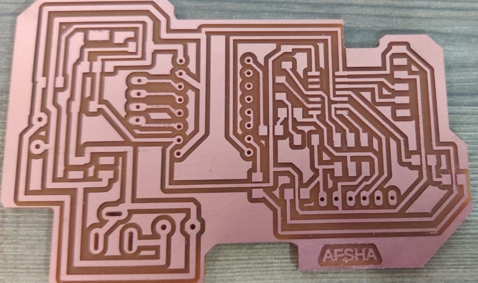
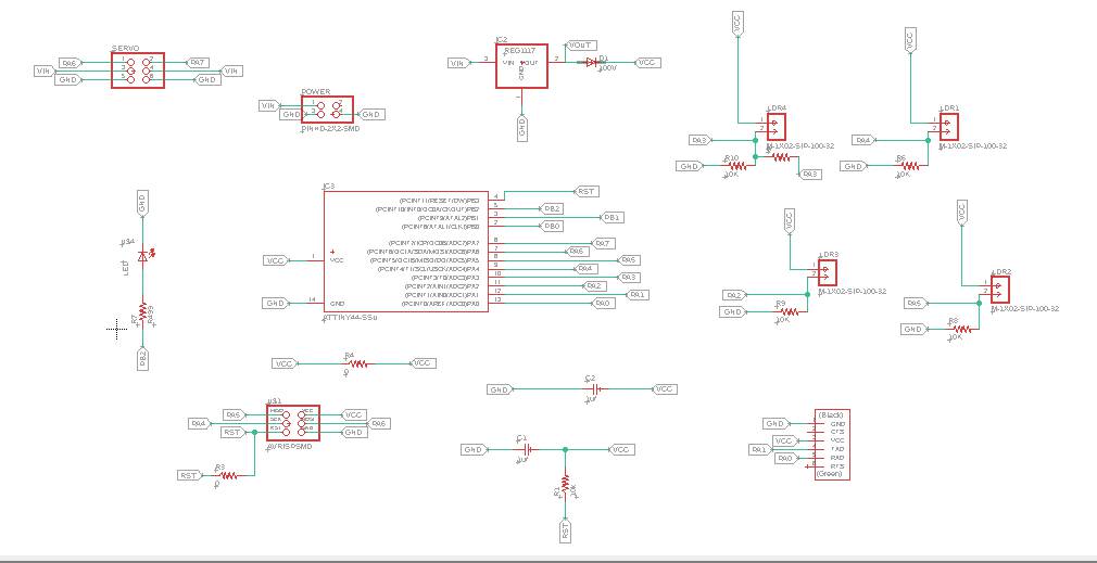
I used Attiny 44 to run stepper motor.PCB Design is as follows:
This is the schematic on Eagle.
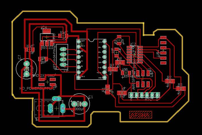
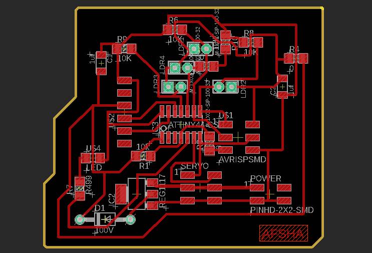
This is the board on Eagle
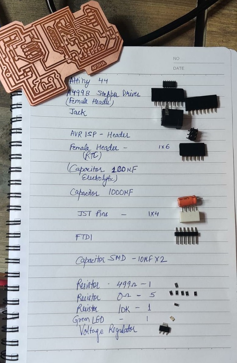
These is the list showing components.
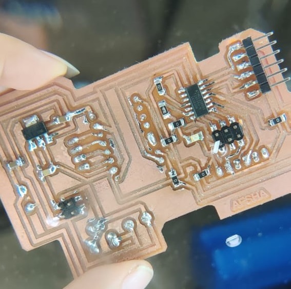
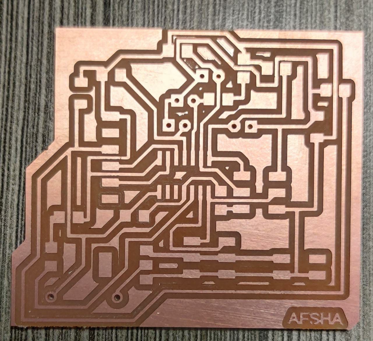
This is the PCB after Soldering.
Here is the video showing Stepper motor moving in clockwise and anticlockwise direction.
SERVO MOTOR AS OUTPUT DEVICE
This is the electronics design file in which I used Attiny 44 for rotating servo motor.I used pwm pins of Attiny 44 as output pins.
Soldering
Here you can see the glimpse of soldering:
This is the working of servo motor :
GROUP ASSIGNMENT
In group assignment we have to measure power of output device.So we decided to measure power consumption of DC Geared motor.
We Connected the Motor to a Variable power supply and observed the current drawn by the motor
Observations
It may be noticed that the current drawn by the motor @ 4 V is about 60mA, and the current drawn by motor @ 10.5 V is about 110mA. So the Power consumption is about :
- Using formula P=VI
- Here P = Power
- >V = voltage
- I = Current
- P = 0.06 * 4 = 0.24 Watt
- P = 0.11 * 10.5 =1.15 Watt
- So the power consumed by motor at No load ranges from 0.24 Watts - 1.1 Watts
Conclusion
Both my output devices Servo Motor and Stepper Motor worked properly.But for final Project, I switched to ATmega 328p.