Computer controlled Machining
This week assignment is about Computer-Aided Manufacturing. In this week I have to explore Laser cutting machine and vinyl plotter. This week I had to design a parametric press-fit kit, and laser cut it.
Getting started with Vinyl Plotter
What is Vinyl Cutter
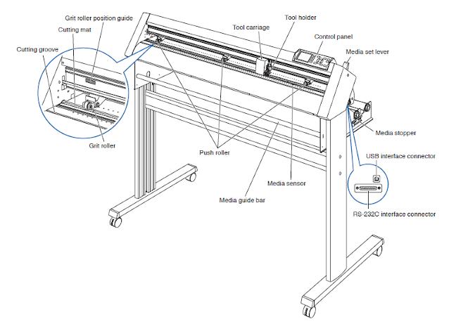
A vinyl cutter is a type of computer-controlled machine. Like a printer controls a nozzle, the computer controls the movement of a sharp blade over the surface of the material. This blade is used to cut out shapes and letters from sheets of thin self-adhesive plastic (vinyl).(Sourece--Wiki)The machine we are using for vinyl cutter is Graphtec-CE-6000 (vinyl cutter).
Vinyl Cutting Workflow
Below are the steps to be followed for operating the machine
- 1. Switch on button of the machine that is on the left back side
- 2. The roll is provided to the machine from the back side where there is a provision of mounting the cylinder on vinyll role.
- 3. Insert the Vinyl sheet parallel to the base of the machine
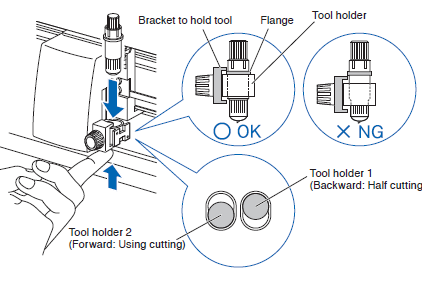
- 4. Rotate the Blade and it should be 0.2 mm outside the blade holder or you can test print some shapes available on the machine interface itself.
- 5. It is therefore required to test print the shapes using different forces and speed at a particular blade length to find out the appropriate characteristic of the machine on which we can work.
- 6. Export the design and send it to the machine using the compatible software which in my case is GRAPHTEC STUDIO.
Setting Parameter and Test Cut
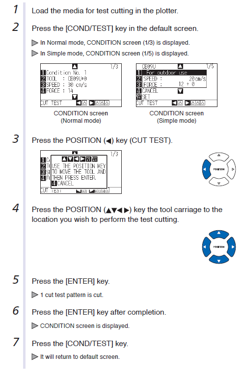

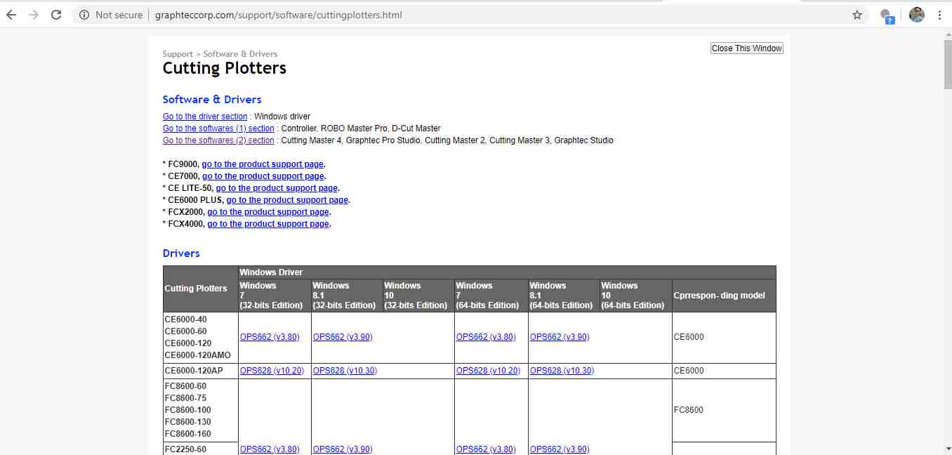
First I downloaded the Graphtec software from this website.
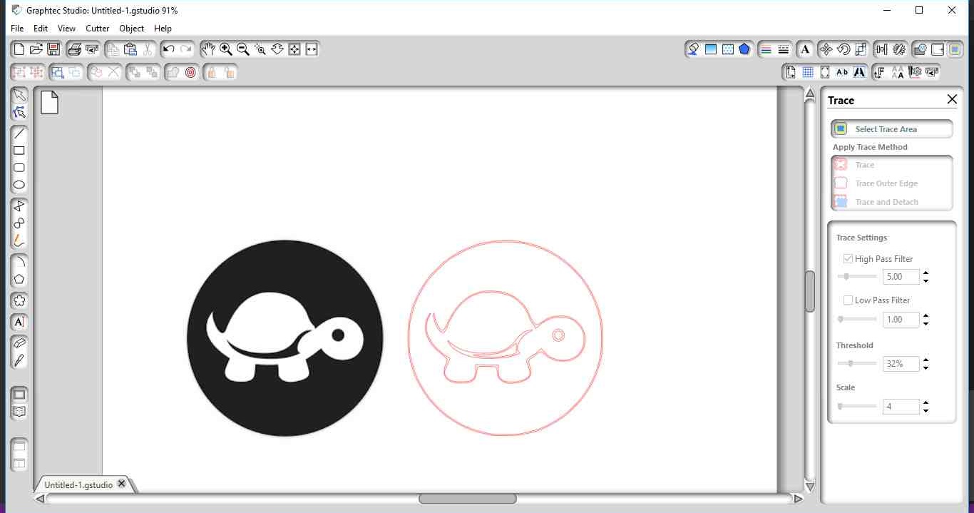
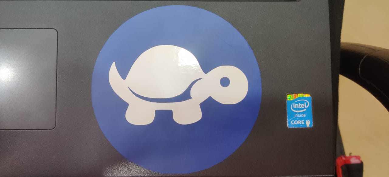
This is the image which I downloaded to go for cutting.

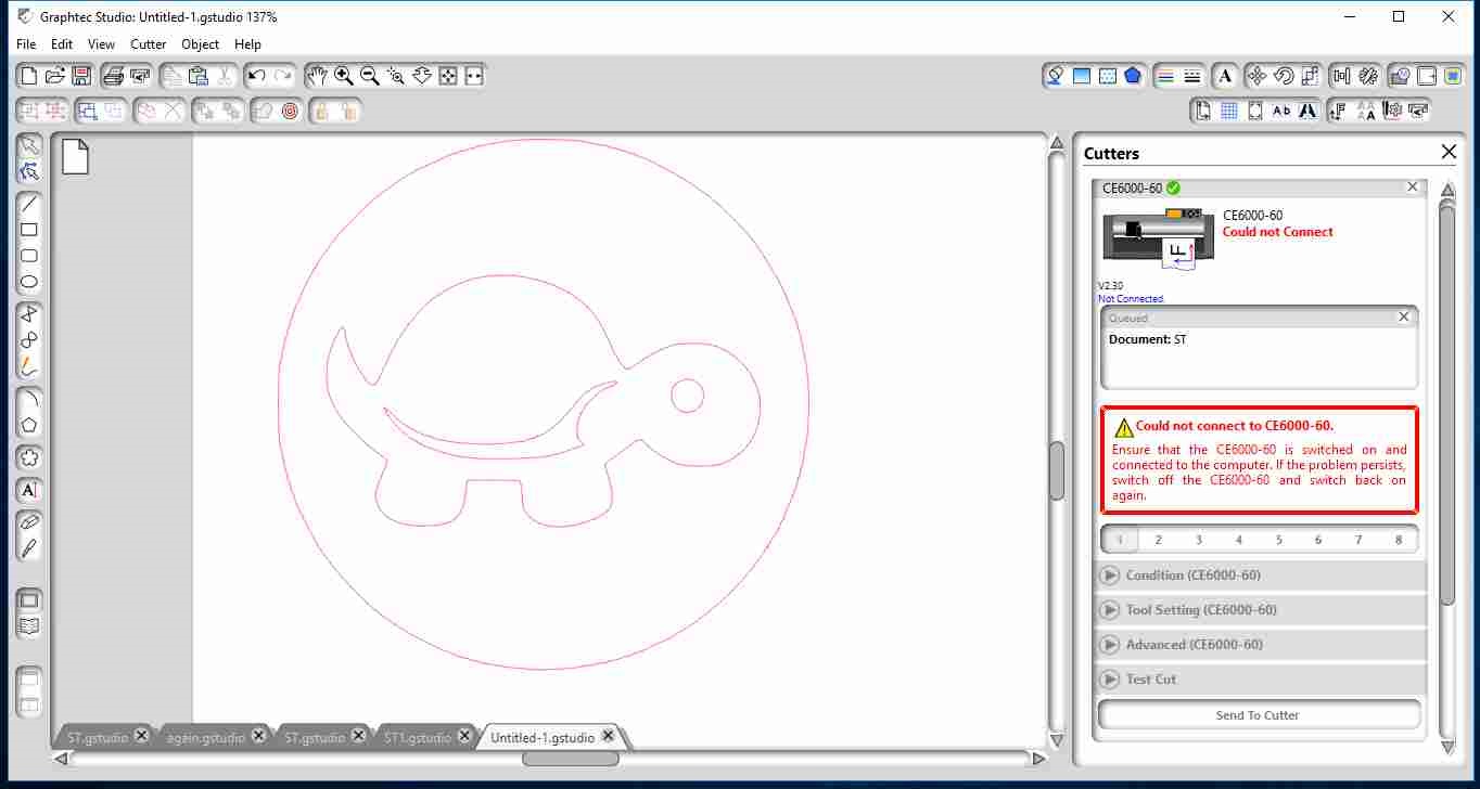
Then I imported it into graphtec studio software.Select the Trace Area option and the area which you want to trace.
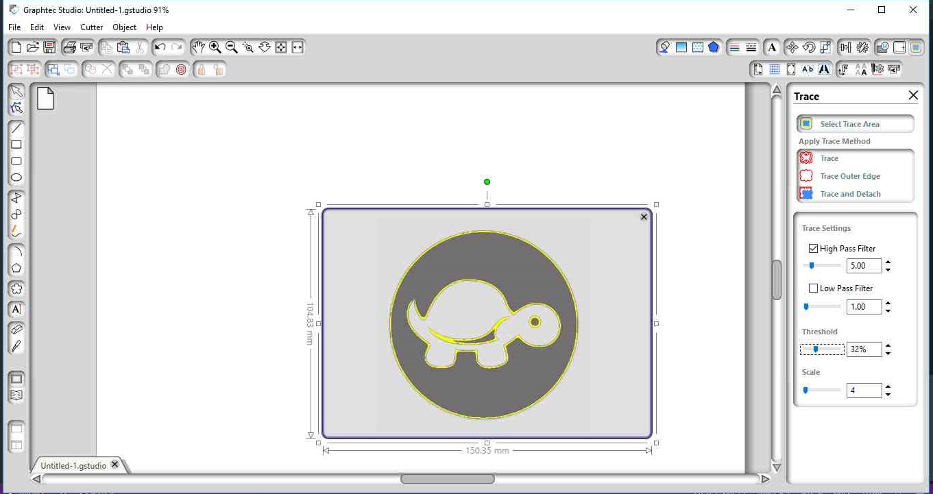
As I trace the image I got to know it is showing two boundaries of turtle.
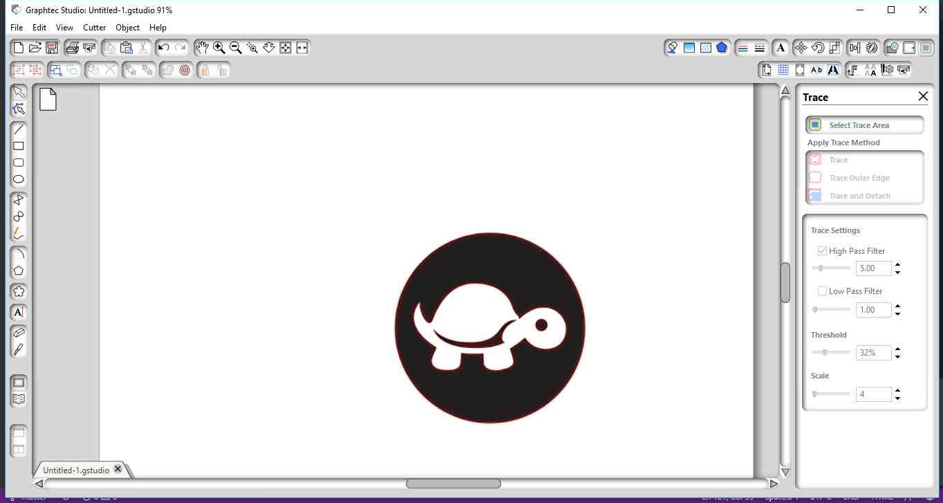
Then by selecting the image I edit the points through edit point option which is at the left corner of software.I clicked on one of the tail corner point and break that point and joint it with other.
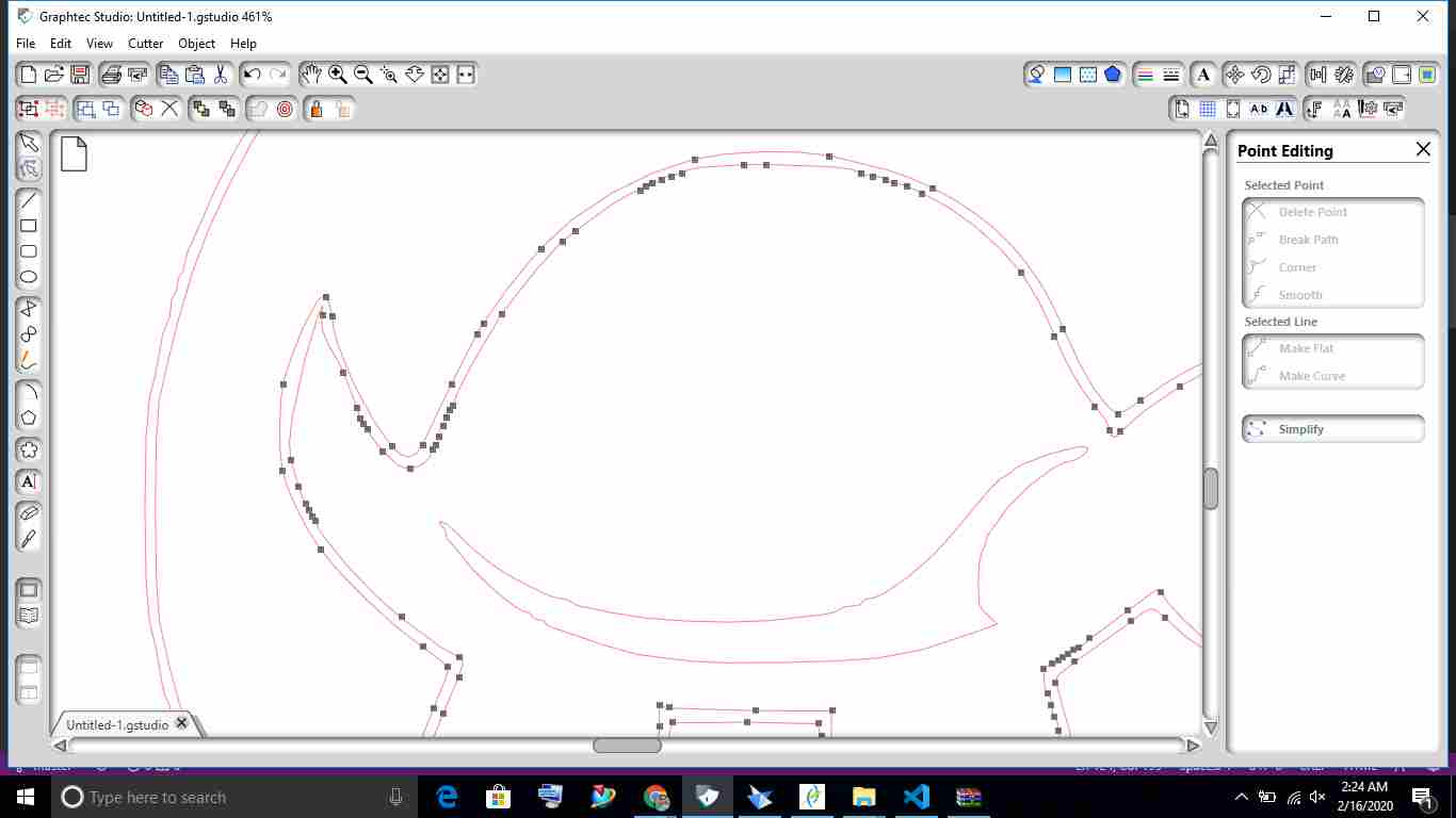
After right cicking on image I also release the path by selecting release compound path.
Then I select the second path and deleted it . The tool position is important for cutting of paper.I set the tool by following step:
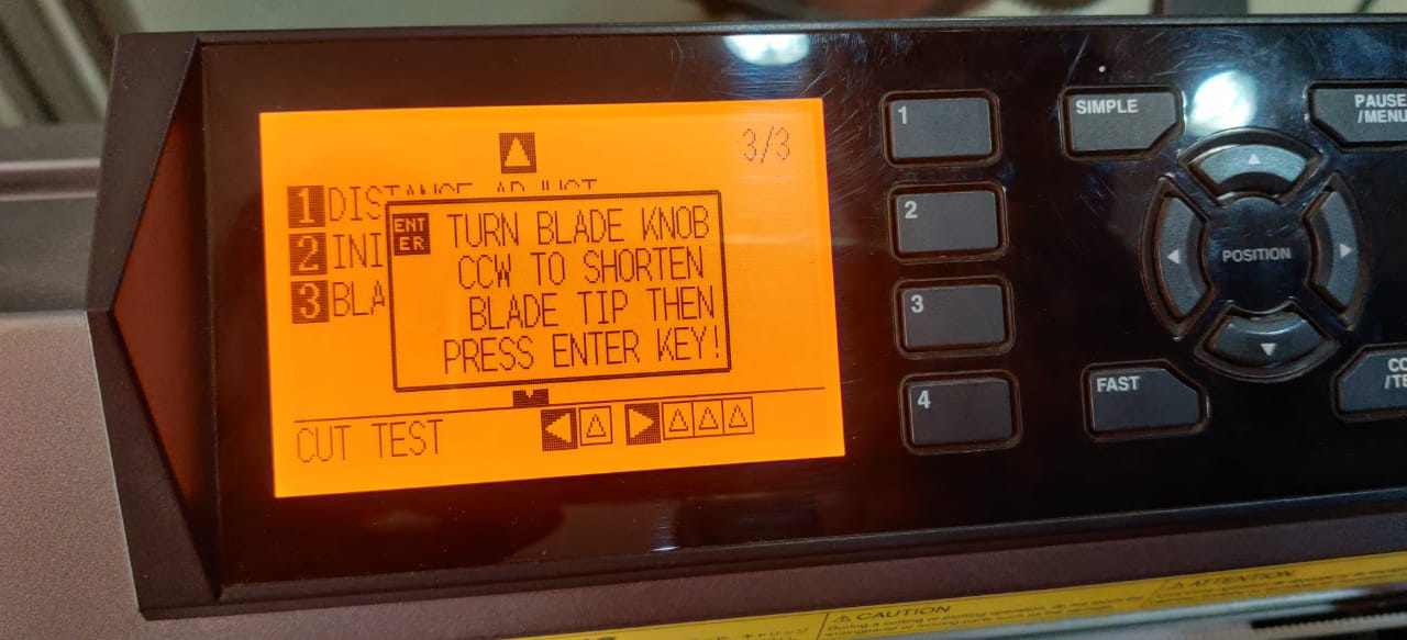
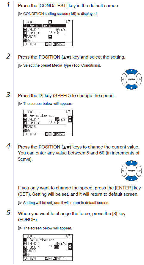
First I do the test cut,the test cut is okay.
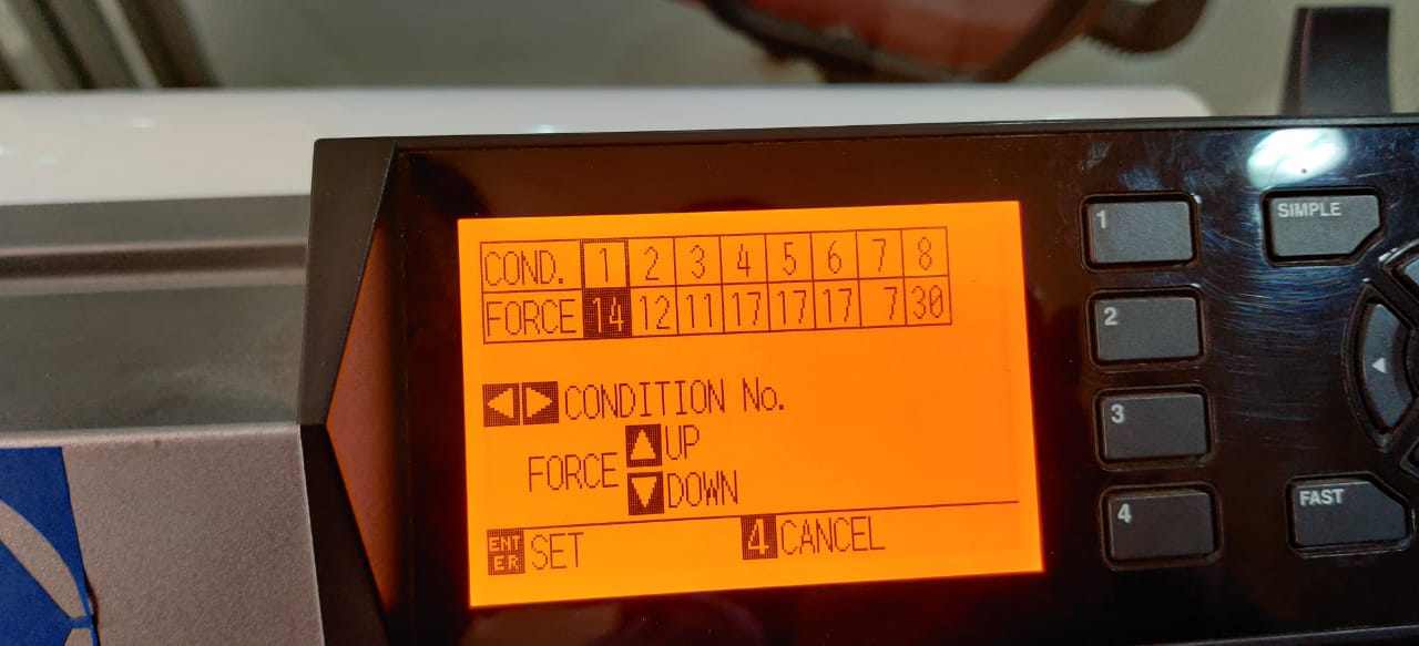
As I want to cut the body of turtle with white color and background with black color. Due to unavailability of black color sticker. I go with blue color. After sending command to cutter.I cut down the body with white color with force setting 14.
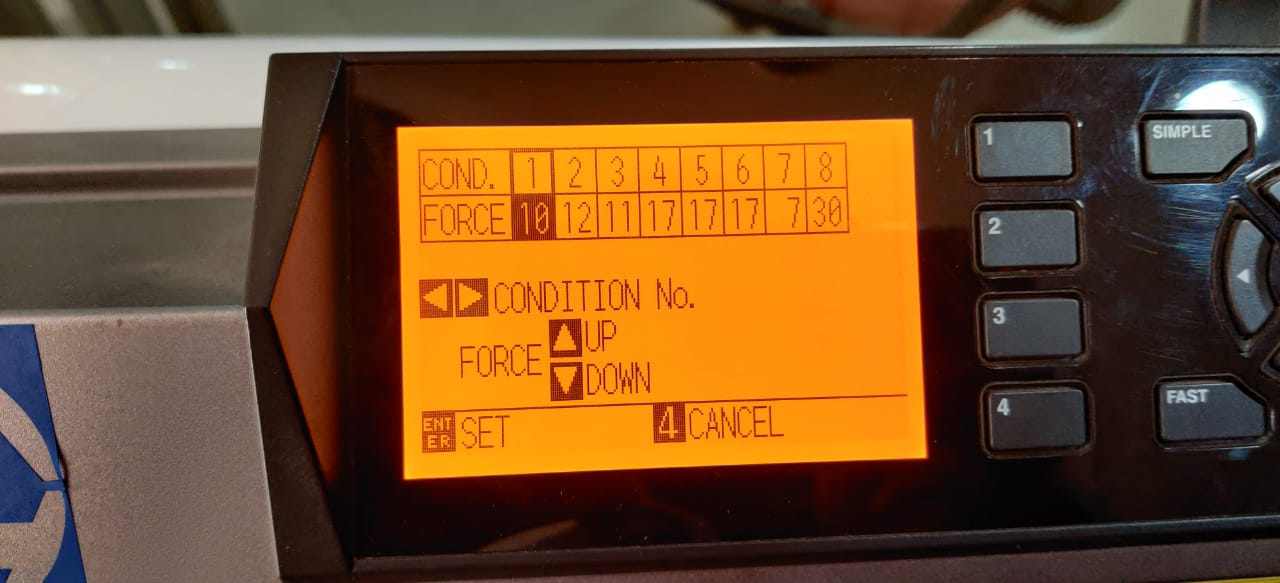
For blue I have to reset the force 10 as the thickness of blue is less. I forgot to take the image of that.
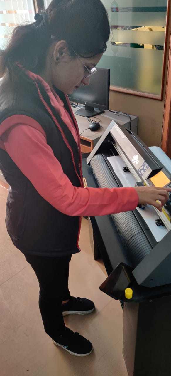
This is me while working on Vinyl plotter.
After weeding that is the process of removing the unwanted vinyl from your cut design.I removed the sticker from vinyl sheet to transfer tape and from transfer tape to my laptop. The results are below:
Sticker Designed on Inkscape
Step 1
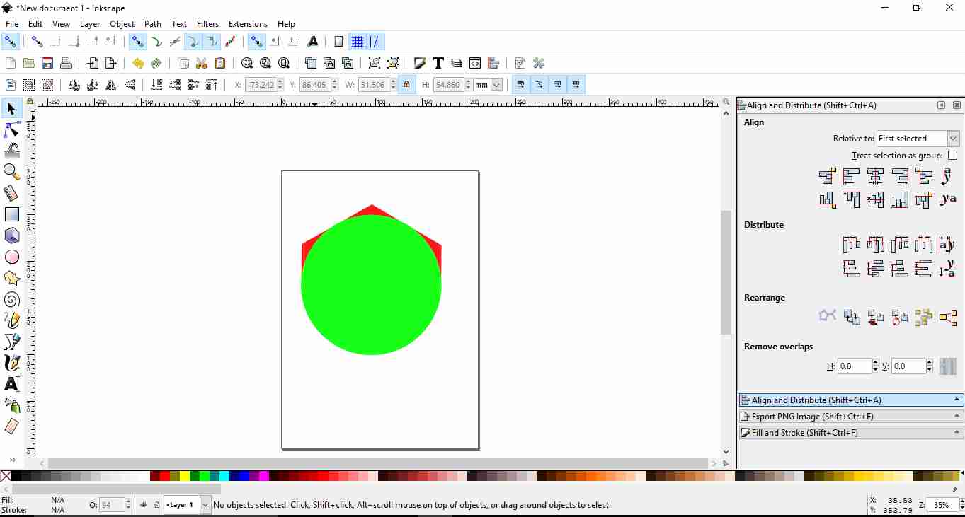
This is the first step in which I made one Hexagon by clicking on Polygon option in left bar corner and then i fill 6 in No of sides.
Step 2
By holding shift and control key.the hexagon made just vertical as required and copied the width on top bar Then I select circle and paste that width in circle width.
Step 3
I aligned circle horizontally and vertically on Hexagon by choosing option Align and Distribute. and then by right clicking on circle i duplicate it.
Step 4
As circle fits Hexagon I select in Path option,first I select Difference and then Break apart so the lower portion got deattached.
Step 5
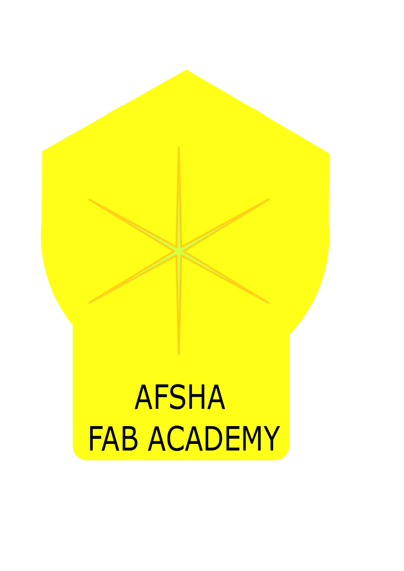
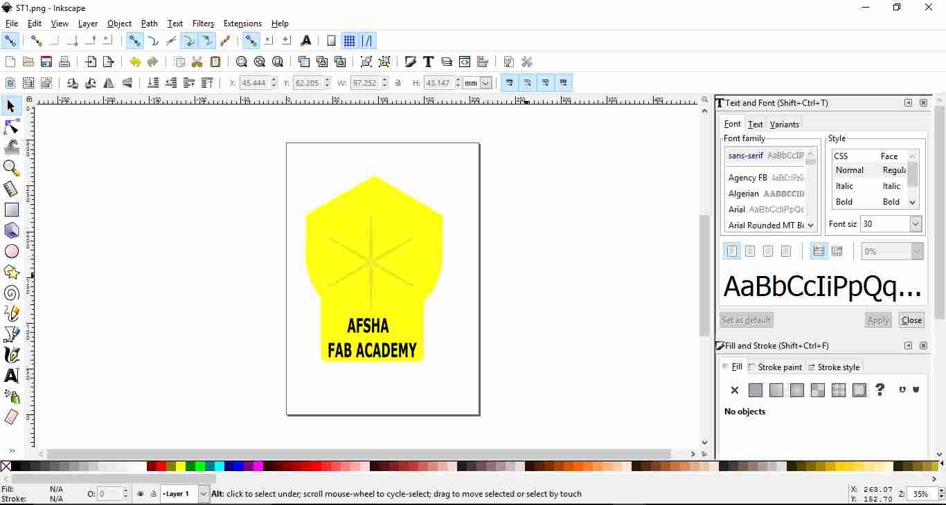
To enter text i select "A" and wrote text AFSHA FABACADEMY and made one rectangle and fill it with background-color and adjusted it.Also used Star command in between.
Step 6
Exported it as PNG and save the file.
Step 6
Then I imported the file in Graphtec studio.After tracing the image I got two outline but they are not connected as in first charset I right click on image and select Release Compound path and selected it and deleted the second outline
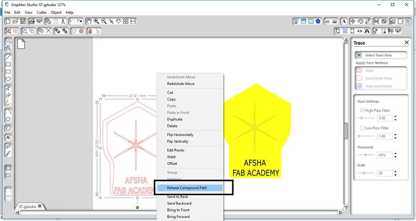
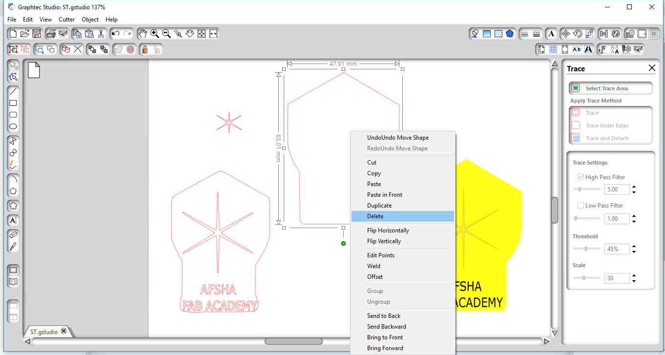
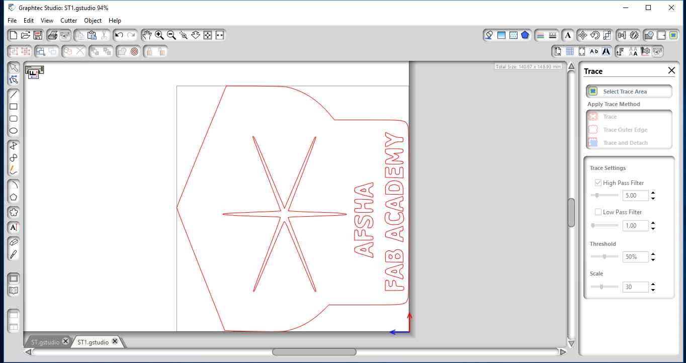
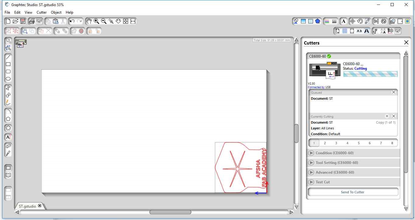
Now it is ready to send to cutter at High Pass Filter-5,low Pass Filter-1 and Threshold-50 .
Step 7
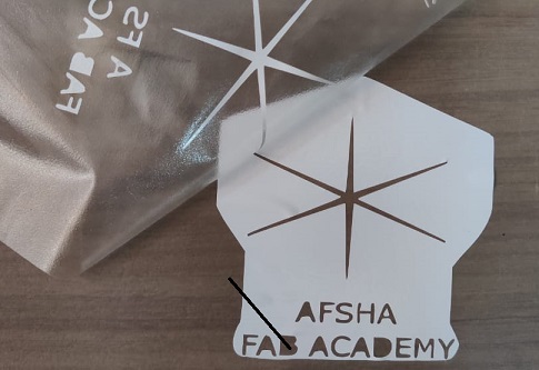
After cutting on Vinyl cutter,this is the image of transfer tape after the sticker transfer on it.
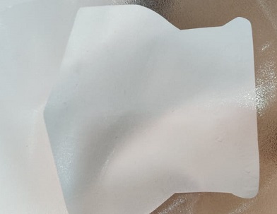
As the text is small the sticker alphabet didnt stick properly on it.
Step 8
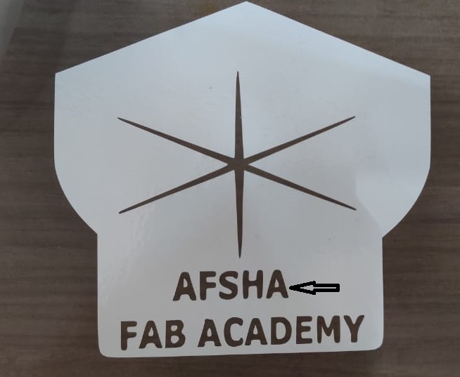
I edit the image again and bold the alphabet like this.
Step 9
This is the final sticker which I made from PNG, designed on Inkscape. With better font and visibility.
Sticker File
Getting started with Laser cutter
What is a laser cutter?
Laser cutter is type of CNC (Computer Numerical Controlled) with a lasser beam. The active laser medium (laser gain/amplification medium) is a gas discharge which is air- or water-cooled, depending on the power being applied. The filling gas within the discharge tube consists of around 10–20% carbon dioxide (CO2), around 10–20% nitrogen (N2), a few percent hydrogen (H2) and/or xenon (Xe) (usually only used in a sealed tube), and the remainder of the gas mixture helium (He). The specific proportions vary according to the particular laser.(source--wiki)KERF
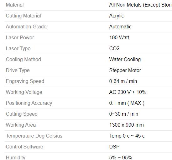
The laser burns away a portion of material when it cuts through. This is known as the laser Kerf and ranges from 0.08mm – 1mm depending on the material type and other conditional factors.The machine we have in AKGEC fablab is SIL CO2 100 watt Laser Cutting machine. The specification of the machines are as follows:
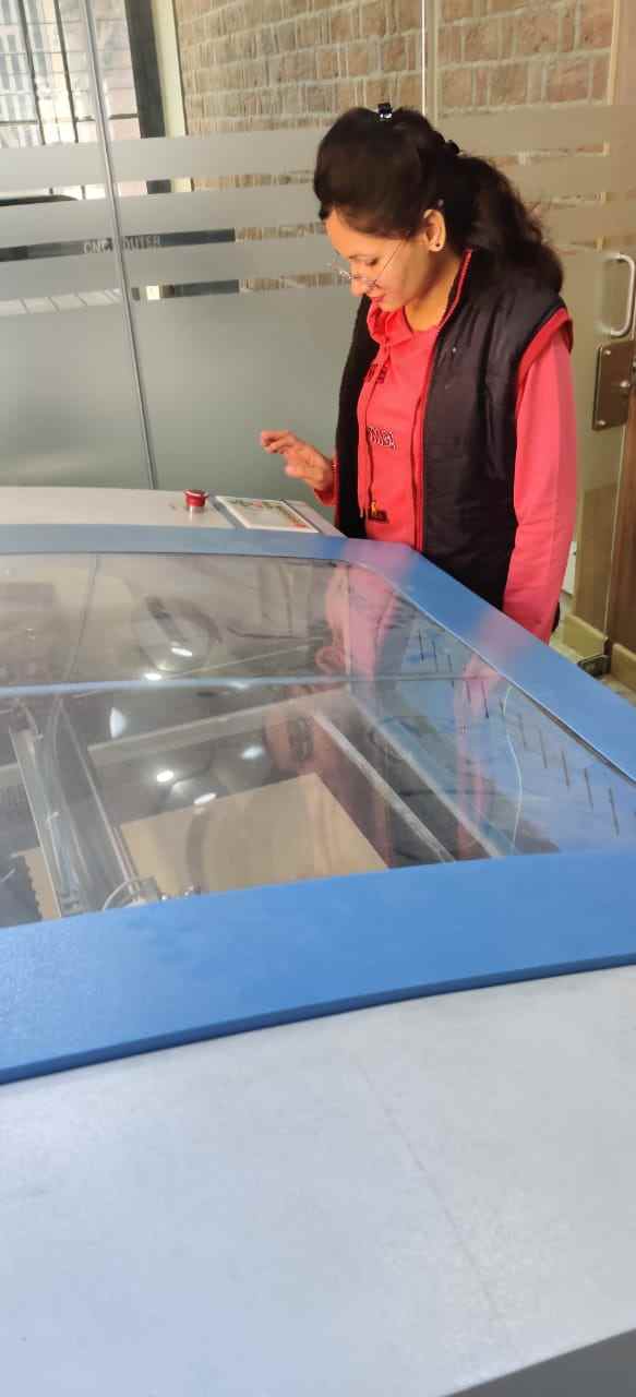
This is me while working on Laser cutting machine:
To operate the machine:
- 1. Power on the switch.
- 2. Switch on the chiller.
- 3. Then set the material on Laser Cutter Bed
- 4. Now there are four red color button at bottom corner of maachine.(Laser, Pointer, Exhaust ,Lamp)
- 5. Turn on Pointer, Exhaust , Lamp first.
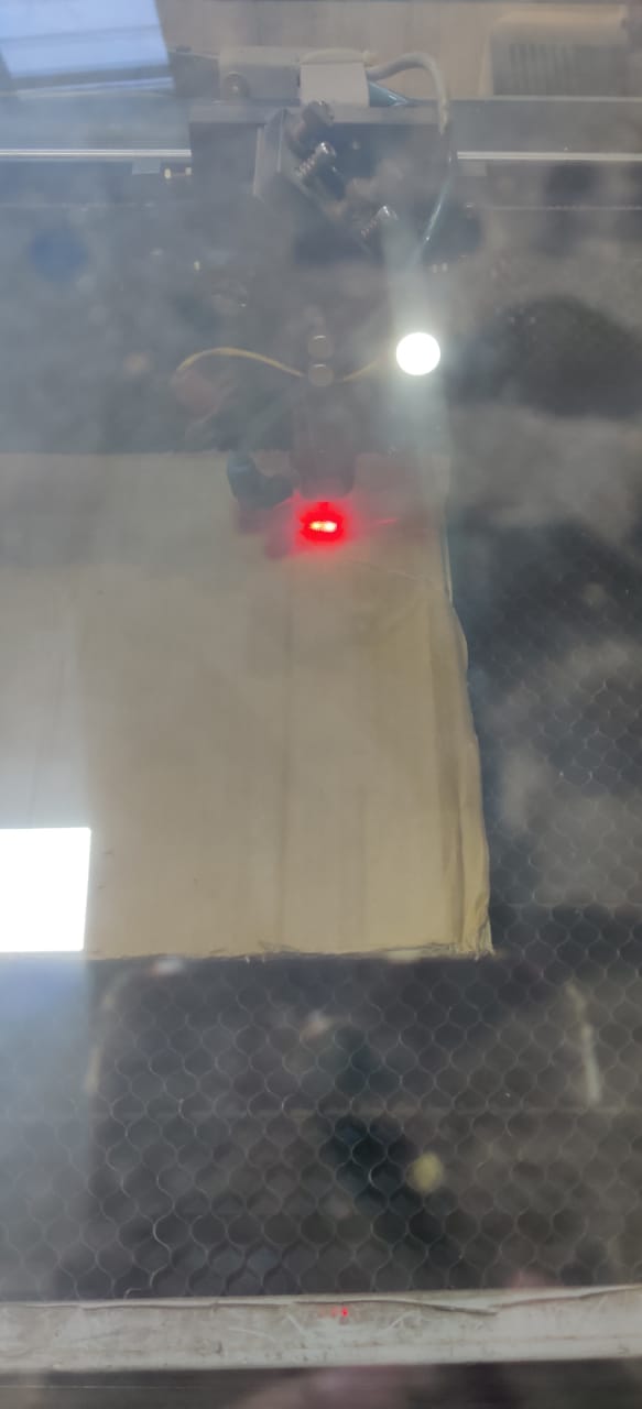
- 6. Focus the pointer by clicking Z up and down button on control panel .
- 7. Connect USB or Cable to laptop in oreder to give comman to laser cut.
- 8. We have to ON the laser button while the output command is given to cutting machine.
Safety Measures while working on machine
- 1. Never leave the laser cutter unattended.
- 2. Only cut materials approved by your instructor.
- 3. Keep the lid closed at all times, unless loading material while the laser is turned off.
- 4. Clean up debris in the laser cutter.
- 5. Identify the fire extinguisher and fire blanket.
For group assignment we decided to cut the 50mm square and calculated the error ie KERF on various power and speed setting as shown in image. The Software used is RD Works which is open source software.Here is a link to download the software .
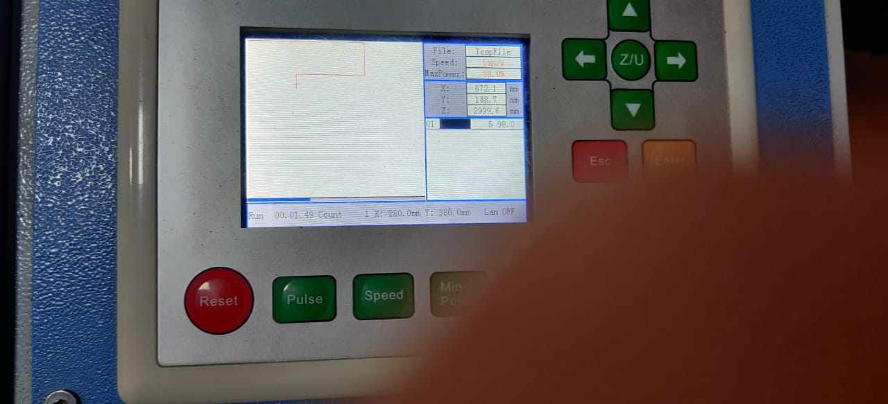
Procedure in RD works :
- 1. Import the .dxf format file into software.
- 2. Set the speed and power for cutting,according to material used.
- 3. Connect the usb cable to laptop having software.
- 4. click on Start. Note : Install the driver in laptop while installing RD Works by connecting USB cable of laser cutter.
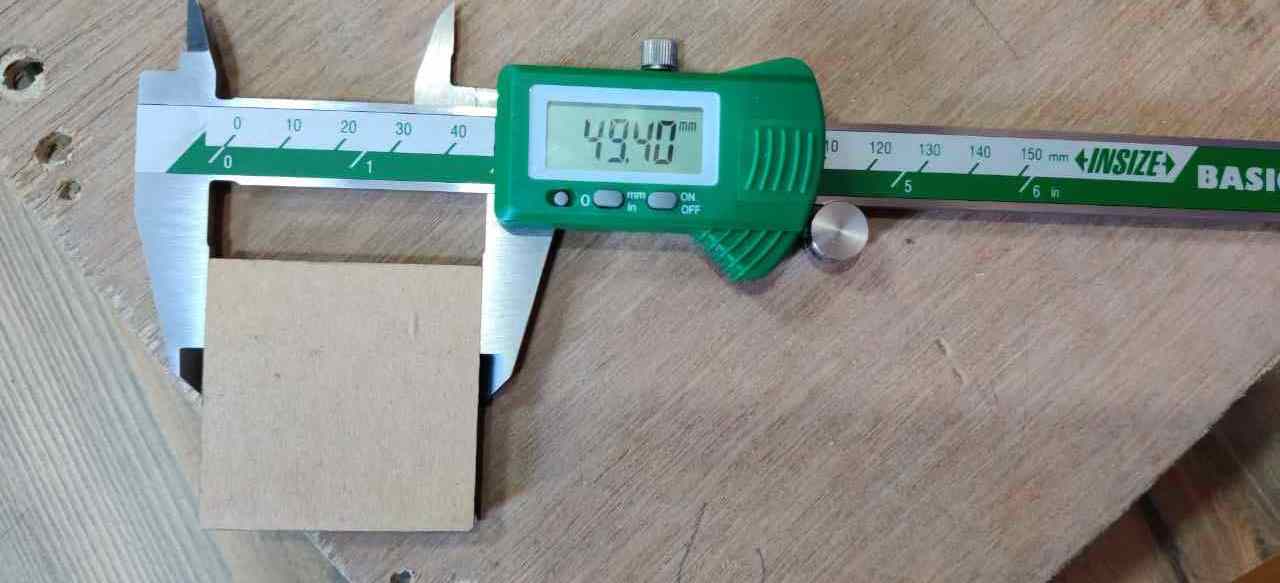
This is the Digital Vernier Calliper showing Kerf on 50 mm Square shape cardboard.So Kerf is calculated by substracting the actual dimension to the dimension came after laser cutting. In this case Kerf=(50mm-49.40mm)=0.6mm and it varies with speed and power configuration.
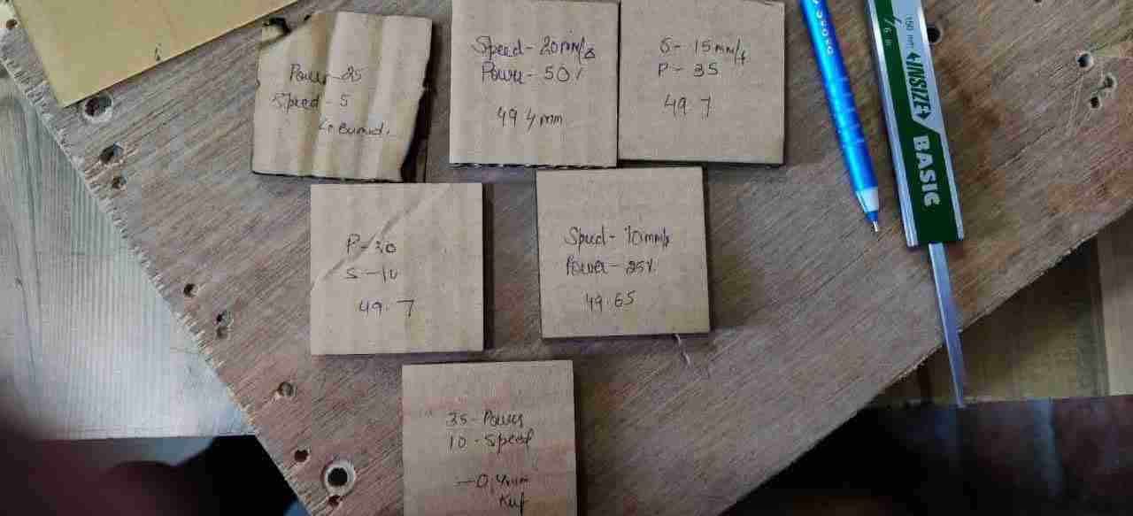
Firstly we dit it on cardboard of 4mm.Here is the list of Kerf for various parameters
Speed 15mm/sec and Power 35% Kerf=0.3mm
Speed 10mm/sec and Power 30% Kerf= 0.3mm
Speed 10mm/sec and Power 25% Kerf=0.35
Speed 10mm/sec and Power 35% Kerf= 0.4mm
Speed 20mm/sec and Power 50% Kerf=0.6mm which is max
After experimenting with power and speed setting I engrave my name on my own diary by setting 10% power and 100mm/sec speed
CUT AND ENGRAVING TEST
In group assignment we decided to go for varying power and speed setting for engraving 10mm square and cut 20mm radius cicle on 3mm Acrylic sheet. Below are the results: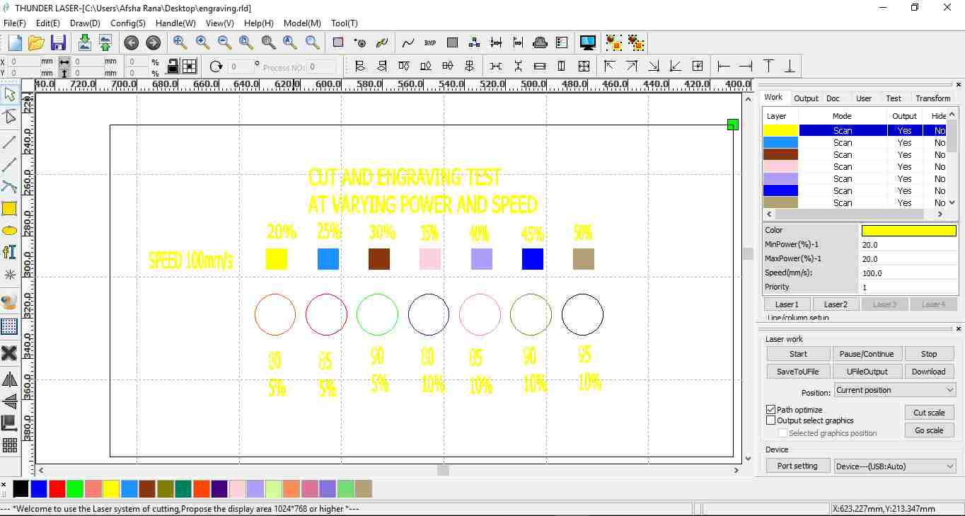
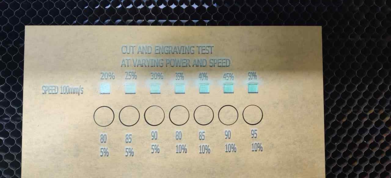
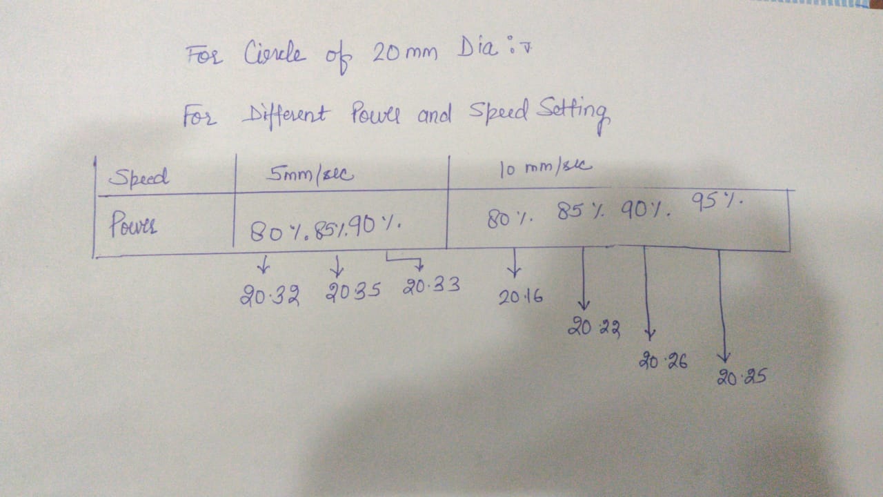
From the test we got outer slots come out to be like the detail in above image and the minimum kerf is in case of Power=80% and Speed=10mm/sec which is 0.16mm
CUT AND ENGRAVING TEST File
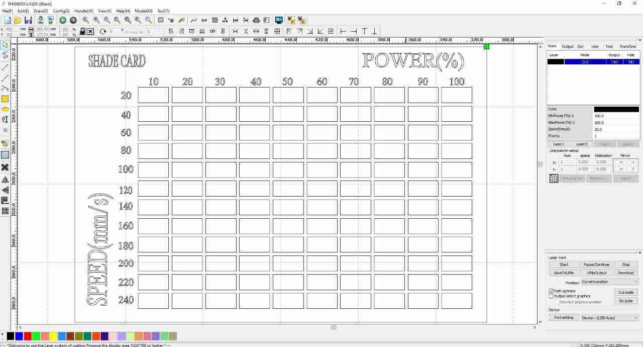
SHADE CARD
We also test one shape card on 3mm transparent Acrylic Sheet
The image is showing the Design on RD works software
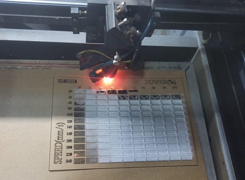
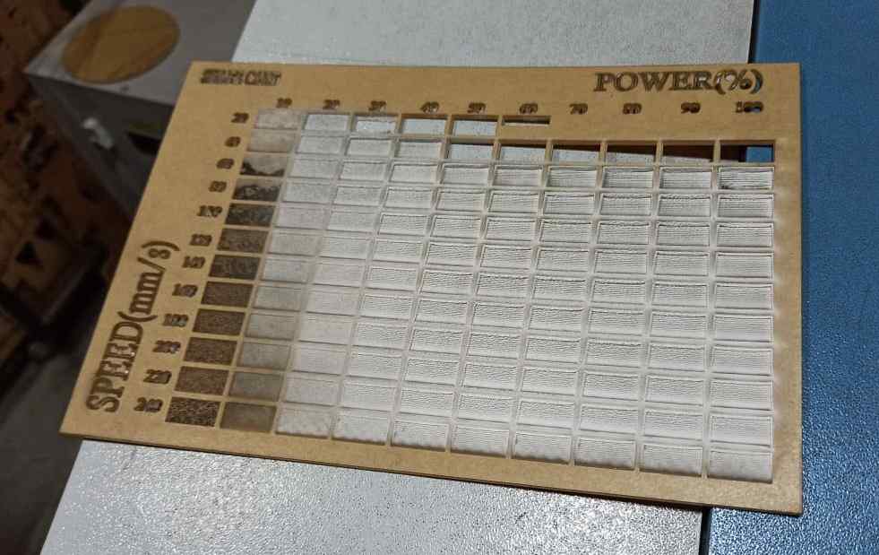
The shade card is showing the engraving on sheet for different power and speed:
SHADE CARD File
Conclusion
As the power increases with less speed setting,the depth increases for engraving. The depth of engraving is less at more speed and increasing power setting.Parametric Kit
What is parametric Design
Parametric means that the model is managed by parameters which include dimensions,thickness etc.
NX is parametric feature based tool as if we want to make a model, it can be controlled by parameter,dimension and geometric constraint.
I used NX-11 for the design. First the circular cross section having slot is made.
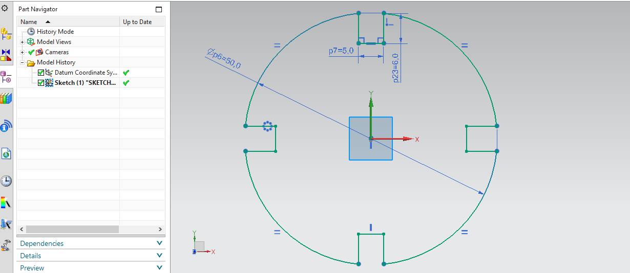
It is showing circular dia 50mm with slot width 5mm.
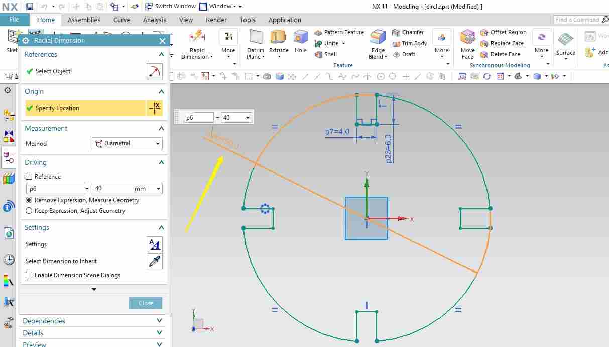
Now the circular cross section dimension changed to 40mm.
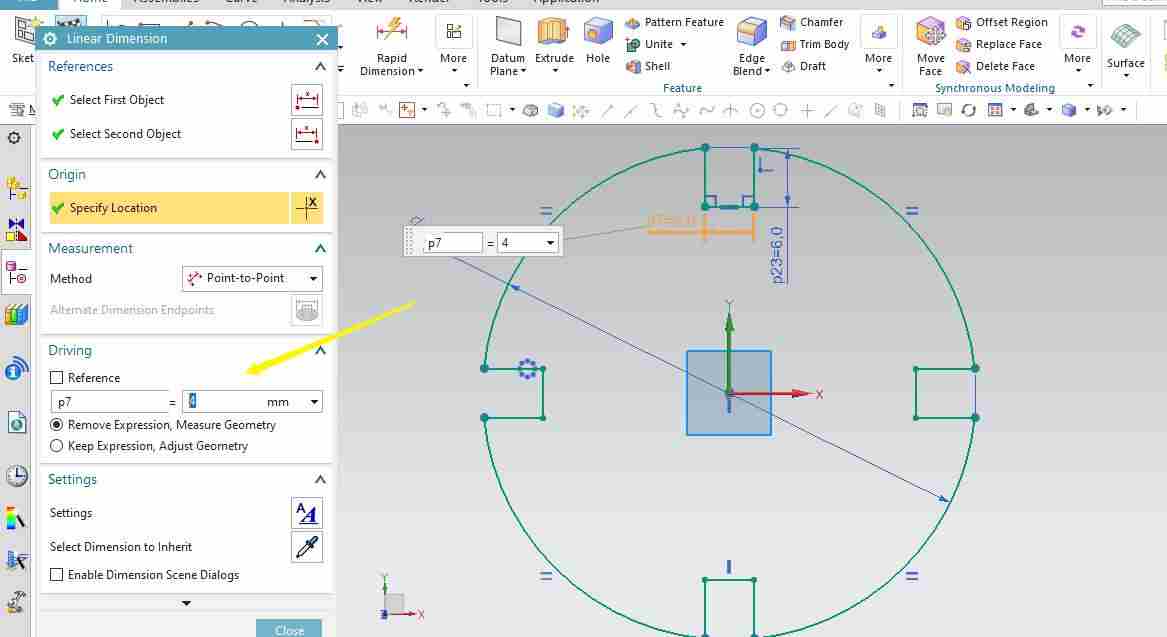
It is showing by double clicking on slot dimension, it has been changed to 4mm.
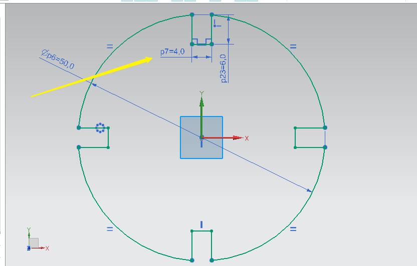
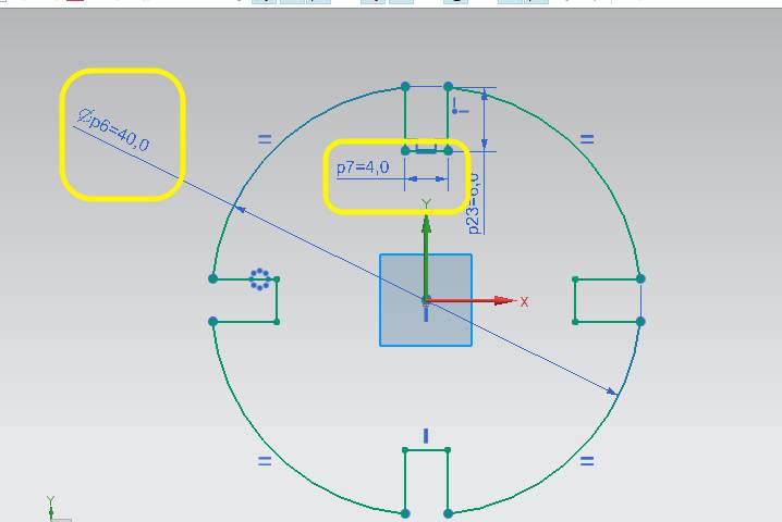
This is showing parameteric design as if I want to change the slots dimension of my design, change in one dimension slot will change the others too accordingly.
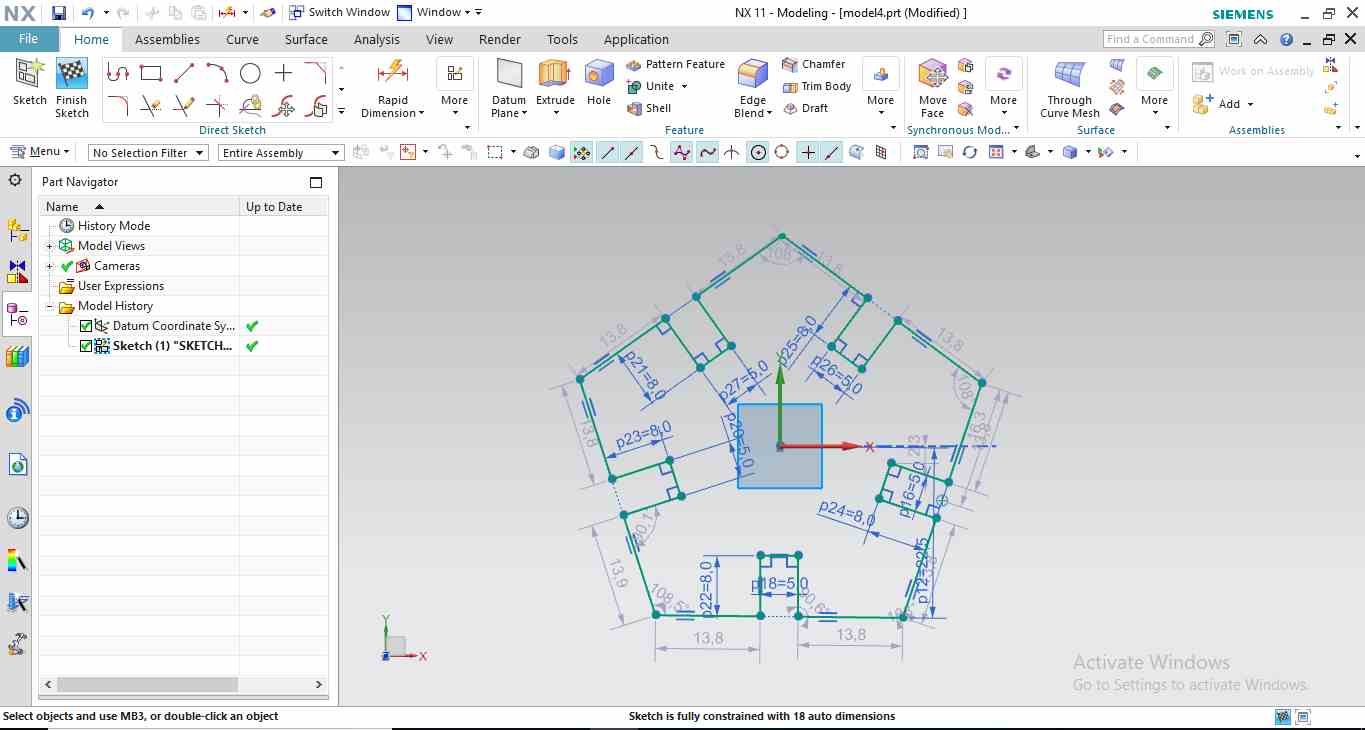
Below is the image showing pentagon having slots on NX-11 using Sketch command,use polygon command in draaw group.
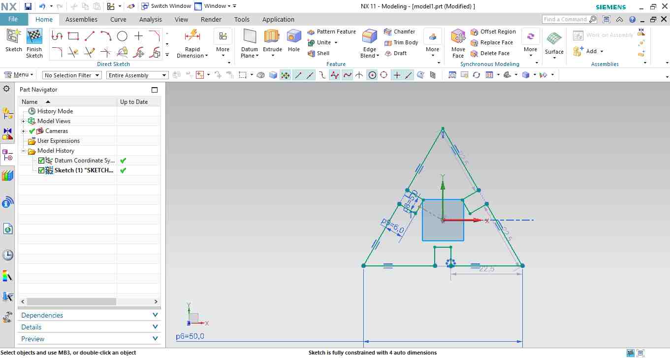
then I made triangular shape with slot.
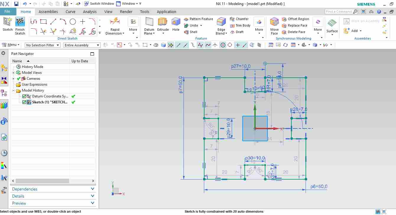
The last shape is rectangle
I Used same setting of power and speed for all the shapes.
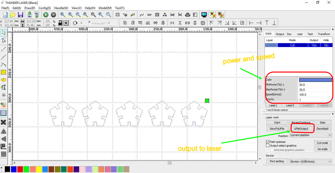
I tried to make "HUT" shape kit on cutting parameter :
- Maximum Power =35
- Minimum Power =35
- Speed=15 mm/sec
- Kerf as calculated for cardboard at Power=35 and Speed = 15mm/sec was 0.3mm
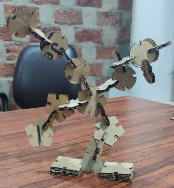
So I made the slots of 4.7mm in order to get 5mm slots in actual but when I tested this cardboard its quality is different it fits in 5mm slot perfectly as well.
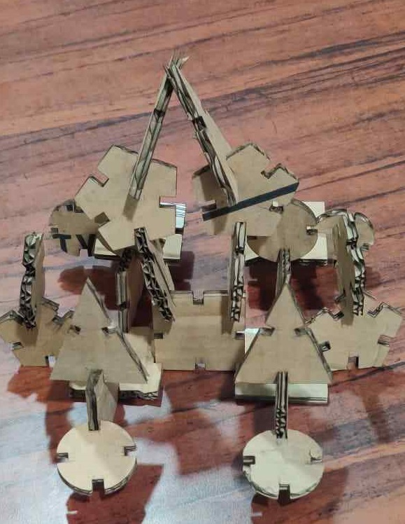
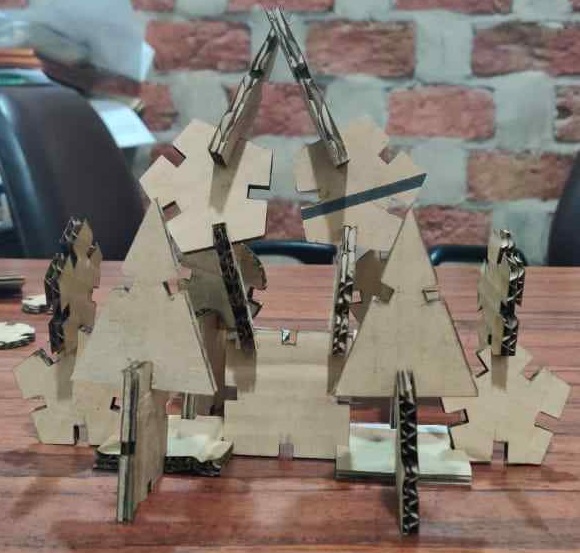
I tried to make "TREE" shape kit on cutting parameter :
- Maximum Power =35
- Minimum Power =35
- Speed=15 mm/sec
- Kerf as calculated for cardboard at Power=35 and Speed = 15mm/sec was 0.3mm
So I made the slots of 4.7mm in order to get 5mm slots in actual but when I tested this cardboard its quality is different it fits in 5mm slot perfectly as well.
Parametric lego Kit File
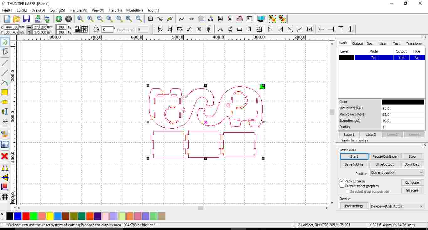
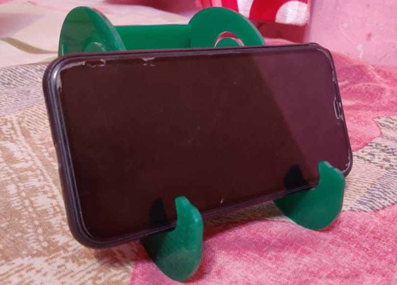
Press Fit Kit on Laser Cutter
The kit which I cut on green color acrylic sheet is having 3mm thickness As I already tested the parameter for 3mm acrylic sheet. So I go for cutting parameter:- Speed =30mm/sec
- Maximum Power =80 %
- Minimum Power =80 %
- Kerf= 0.4mm
Design was made in order that 0.4 mm less dimension was taken where slots was there.
Below are the images: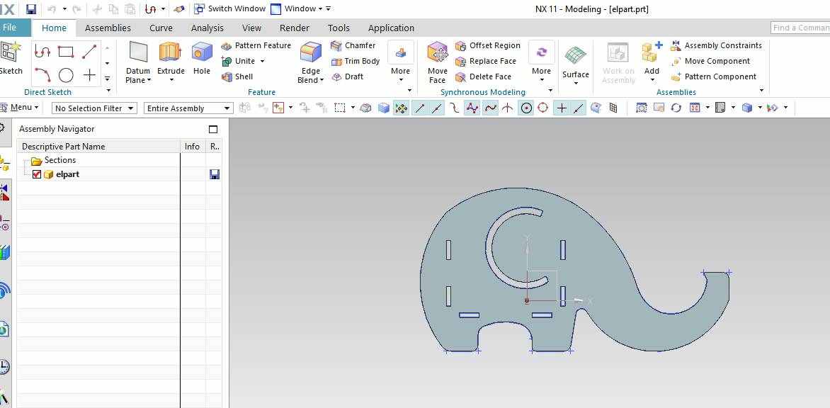
Design of side support on NX.
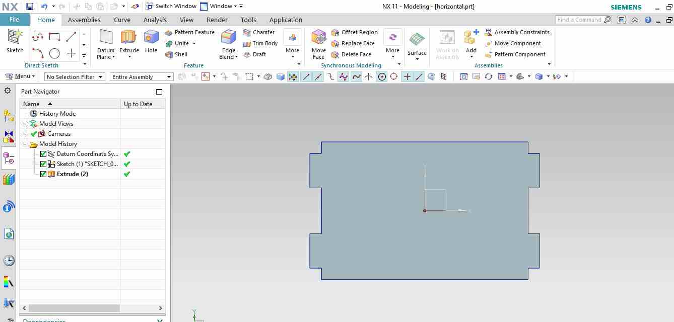
Design of horizontal support.
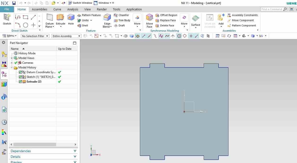
Design of vertical support.
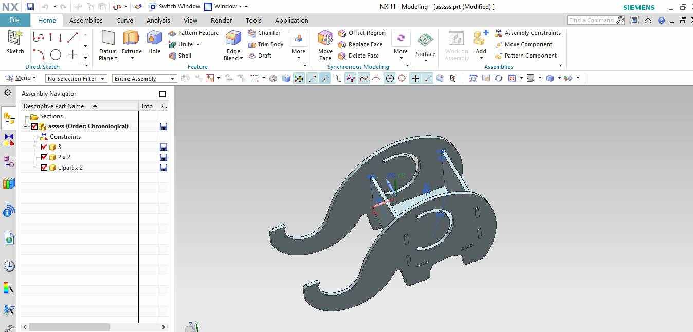
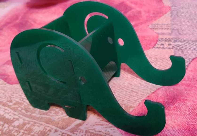
Assembly on NX
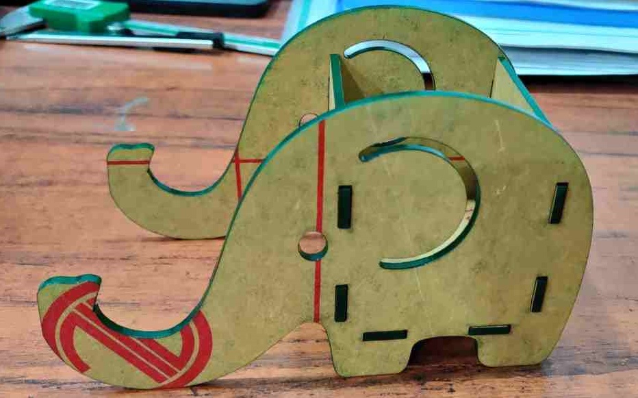
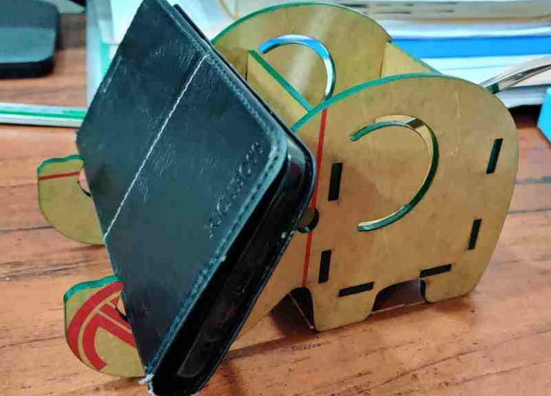
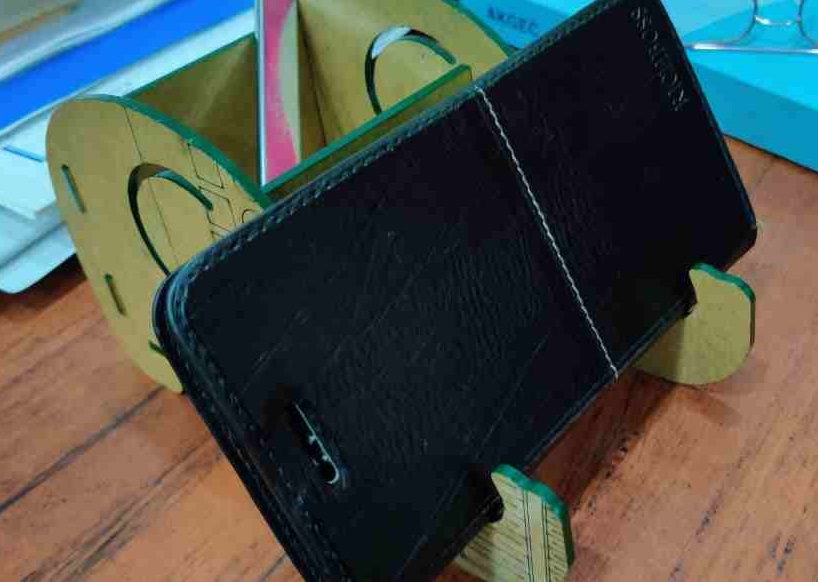
After removing paper from acrylic sheet
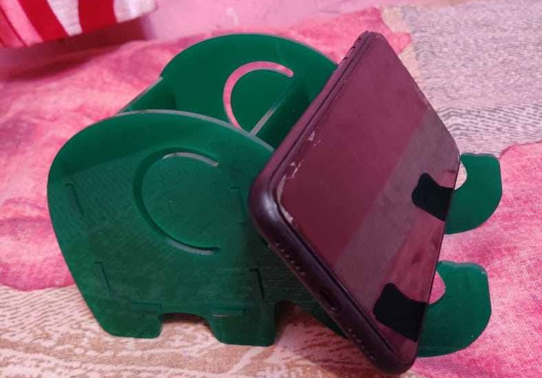
The pen and phone stand is ready.
Press Fit Kit File
All Files can be downloaded from