Input Device
- Individual Assignment:
- measure something: add a sensor to a microcontroller board.
- that you have designed and read it.
- Group Assignment:
- probe an input device's analog levels and digital signals.
Sensors
A sensor is a device that detects changes and events in a physical stimulus and provides a corresponding output signal that can be measured and/or recorded. Here, the output signal can be any measurable signal and is generally an electrical quantity.
Analog Sensors
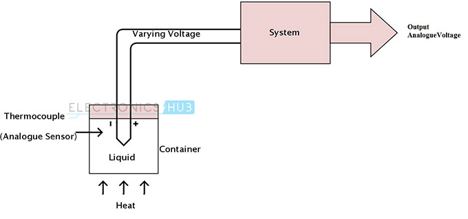
An analog sensor produces continuously varying output signals over a range of values. Usually the output signal is voltage and this output signal is proportional to the measurand. The quantity that is being measured like speed, temperature, pressure, strain, etc. are all continuous in nature and hence they are analogue quantities A thermocouple or a thermometer is an analog sensor. The following setup is used to measure the temperature of the liquid in the container using a thermocouple.
Digital Sensors
A digital sensor produces discrete digital signals. The output of a digital sensor has only two states, namely ‘ON’ and ‘OFF’. ON is logic 1 and OFF is logic 0. A push button switch is the best example of a digital sensor. In this case, the switch has only two possible states: either it is ON when pushed or it is OFF when released or not pushed. The following setup uses a light sensor to measure the speed and produces a digital signal.
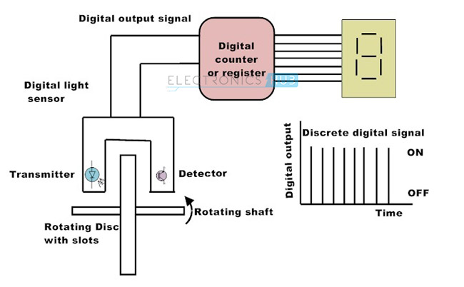
In the above setup, the rotating disc is connected to the shaft of a motor and has number of transparent slots. The light sensor captures the presence or absence of the light and sends logic 1 or logic 0 signal accordingly to the counter. The counter displays the speed of the disc. The accuracy can be increased by increasing the transparent slots on the disc as it allows more counts over the same amount of time.
Actuators
Actuators are devices that work opposite to sensors. A sensor converts a physical event into an electrical signal, whereas an actuator converts electrical signal into a physical event. When sensors are used at input of a system, actuators are used to perform output function in a system as they control an external device.
Transducers
Transducers are the devices that convert energy in one form into another form. Generally the energy is in the form of a signal. Transducer is a term collectively used for both sensors and actuators.
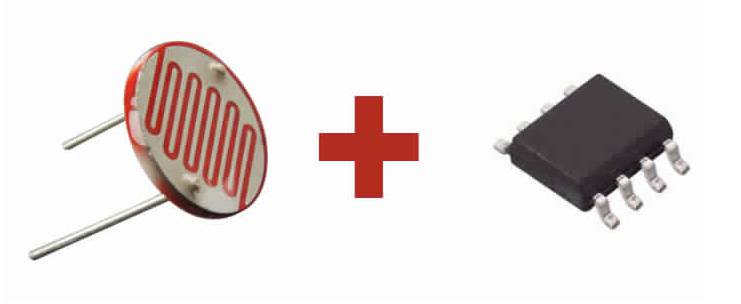
Source :For this assignment a board was developed which is responsible for capturing an analog signal by means of the LDR sensor by which we can perceive variations of light. To accomplish this, an attiny 45 with a pin with analog input will be used to capture the voltage variation of the sensor.
Components
- Attiny 45
- LDR
- Resistance 10k
- Resistance 220 ohm
- LED
Light Dependent Resistor
The Light Dependent Resistor (LDR) is just another special type of Resistor and hence has no polarity. Meaning they can be connected in any direction. They are breadboard friendly and can be easily used on a perf board also. The symbol for LDR is just as similar to Resistor but adds to inward arrows . The arrows indicate the light signals. A photoresistor or LDR (Light Dependent Resistor), as the name suggests will change it resistance based on the light around it. That is when the resistor is placed in a dark room it will have a resistance of few Mega ohms and as we gradually impose light over the sensor its resistance will start to decrease from Mega Ohms to few Ohms.
LDR Features
- 1. Can be used to sense Light
- 2. Easy to use on Breadboard or Perf Board
- 3. Easy to use with Microcontrollers or even with normal Digital/Analog IC
- 4. Small, cheap and easily available
- 5. Available in PG5 ,PG5-MP, PG12, PG12-MP, PG20 and PG20-MP series
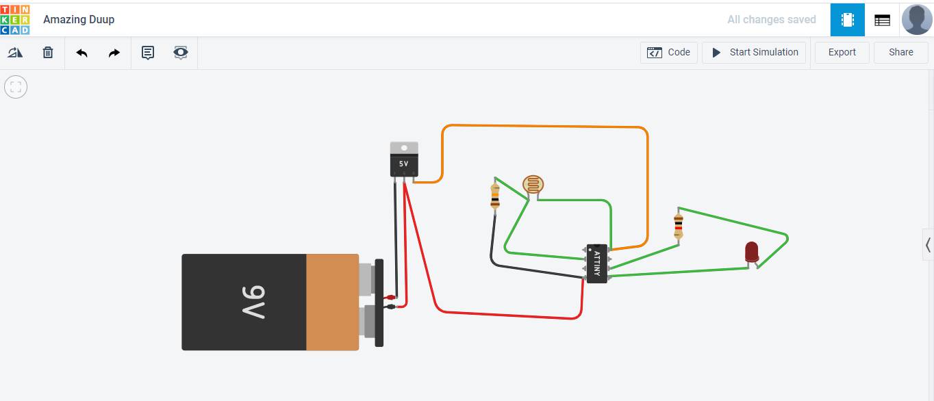
In the datasheet we can find the information on all the pins that the micorcontroller has and if they are analog or digital in this compose we have 3 analog and 6 digital. to be able to control the LDR sensor with the microcontroller we will need an analog pin and to be able to verify this we will use a led connected to a digital pin which will turn on and off based on the light capture of the LDR.
Simulation on Tinker Cad
LDR SENSOR
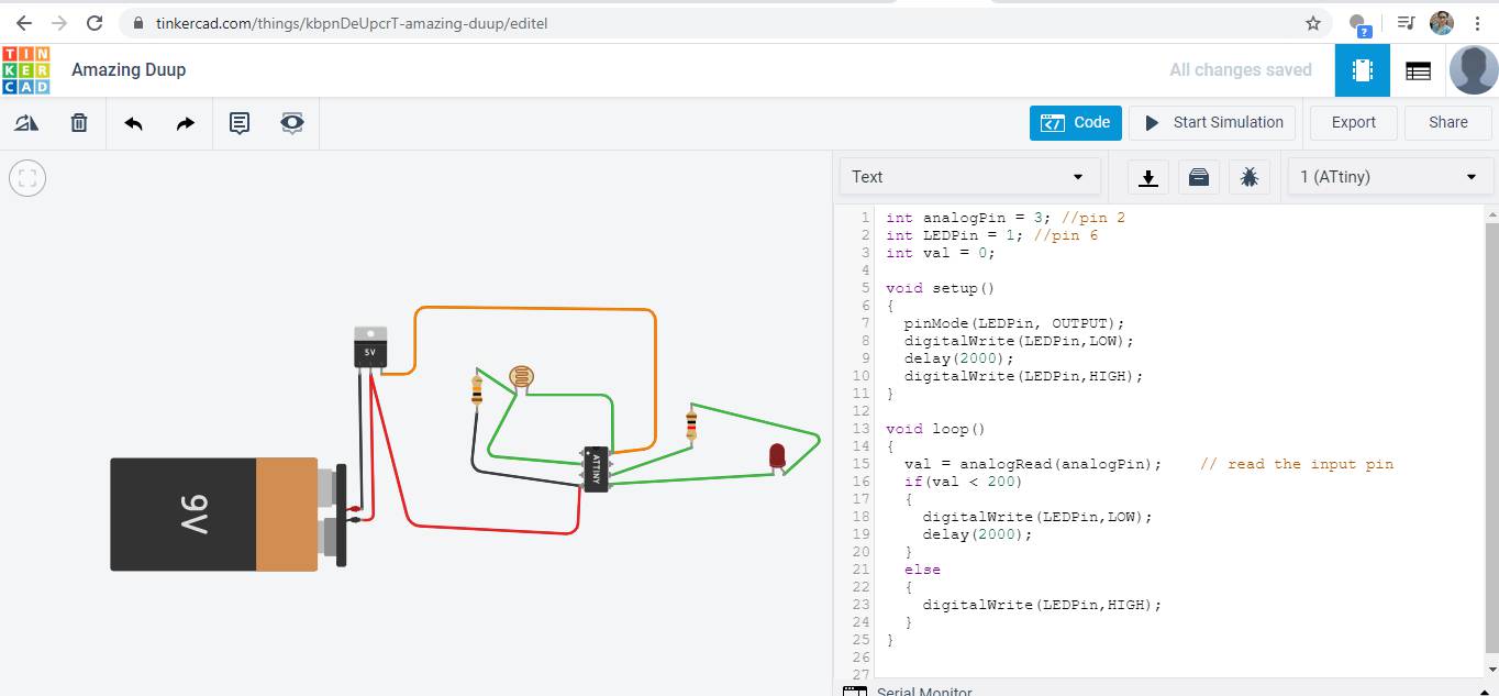
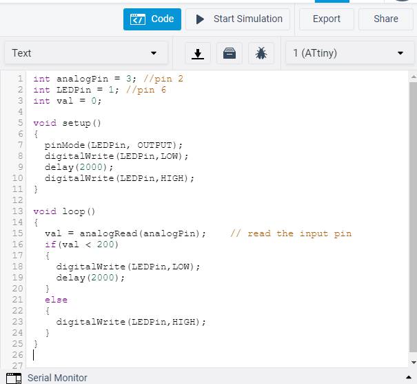
  int analogPin = 3; //pin 2
  int LEDPin = 1; //pin 6
  int val = 0;

  void setup()
  {
    pinMode(LEDPin, OUTPUT);
    digitalWrite(LEDPin,LOW);
    delay(2000);
    digitalWrite(LEDPin,HIGH);
  }

  void loop()
  {
    val = analogRead(analogPin);    // read the input pin
    if(val < 200)
    {
      digitalWrite(LEDPin,LOW);
      delay(2000);
    }
    else
    {
      digitalWrite(LEDPin,HIGH);
    }
  }
Heree is the video for same.
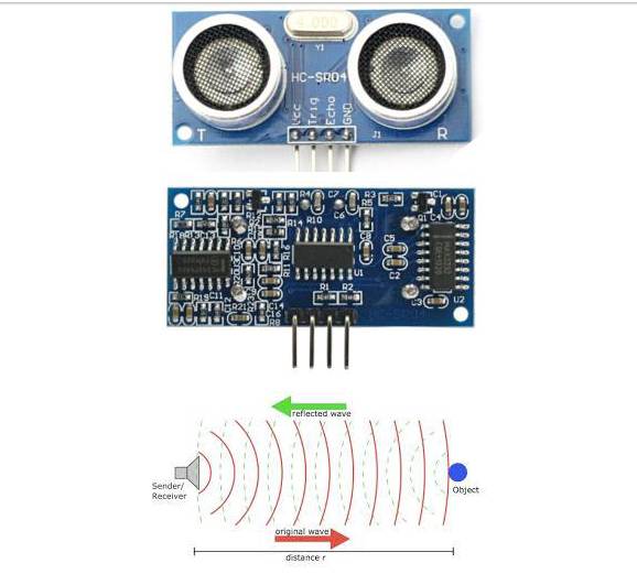
Ultrasonic Sensor
The HC-SR04 ultrasonic sensor uses SONAR to determine the distance of an object just like the bats do. It offers excellent non-contact range detection with high accuracy and stable readings in an easy-to-use package from 2 cm to 400 cm or 1” to 13 feet.
The operation is not affected by sunlight or black material, although acoustically, soft materials like cloth can be difficult to detect. It comes complete with ultrasonic transmitter and receiver module.Technical Specifications
- Power Supply − +5V DC
- Quiescent Current − less than 2mA
- Working Current − 15mA
- Effectual Angle − less than 15°
- Ranging Distance − 2cm – 400 cm/1″ – 13ft
- >Resolution − 0.3 cm Measuring Angle − 30 degree
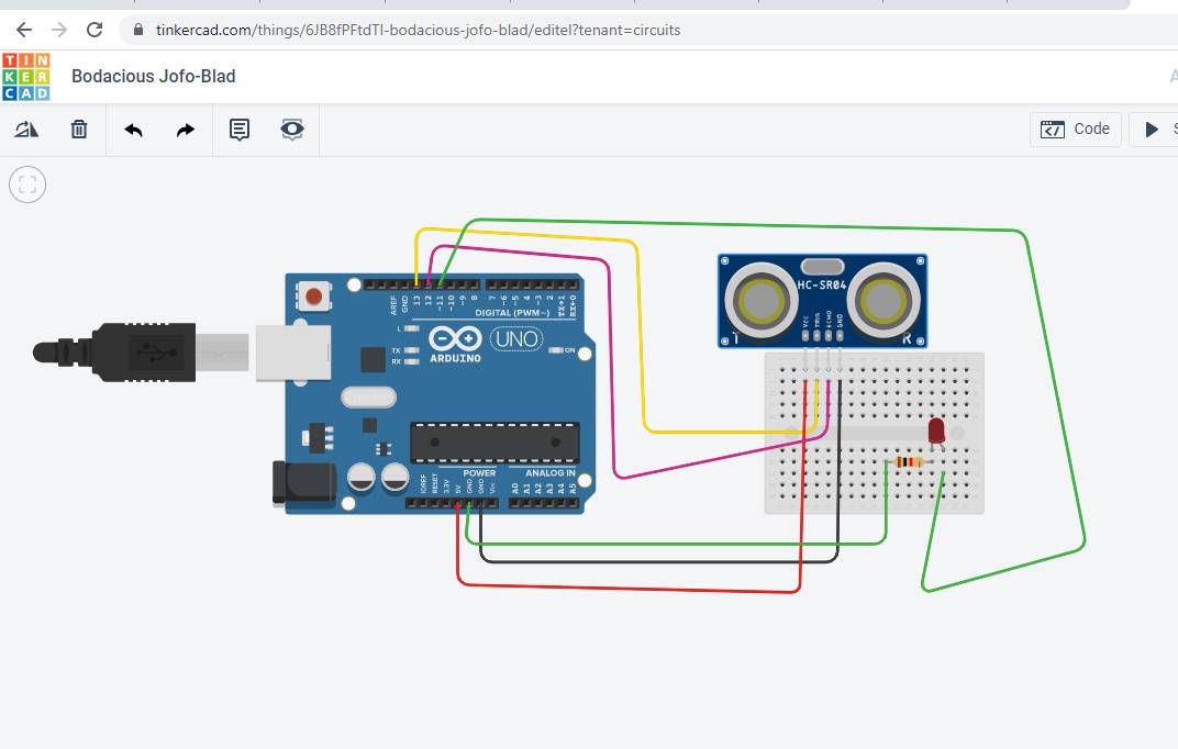
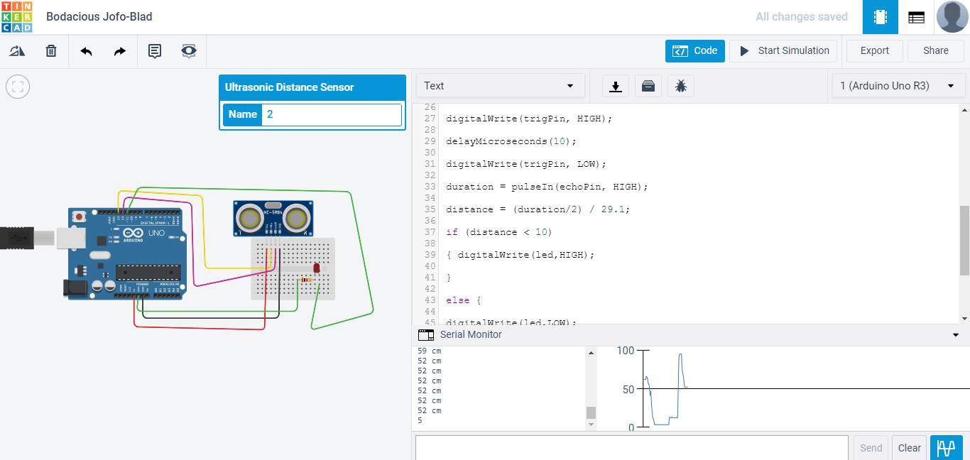
I tried simulation on Arduino with Ultrasonic Sensor
#define trigPin 13

    #define echoPin 12
    #define led 11
    void setup()
    { Serial.begin (9600);
    pinMode(trigPin, OUTPUT);
    pinMode(echoPin, INPUT);
    pinMode(led, OUTPUT);
    }

    void loop()
    { long duration, distance;
    digitalWrite(trigPin, LOW);
    delayMicroseconds(2);
    digitalWrite(trigPin, HIGH);
    delayMicroseconds(10);
    digitalWrite(trigPin, LOW);
    duration = pulseIn(echoPin, HIGH);
    distance = (duration/2) / 29.1;
    if (distance < 10)
    { digitalWrite(led,HIGH);
    }
    else {
    digitalWrite(led,LOW);
    }
    Serial.print(distance);
    Serial.println(" cm");
    delay(500);
    }
Working on Attiny 45
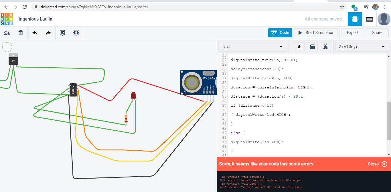
As Attiny does not have serial communication abilities.So i edit the code and remove timing and serial communication protocal.Now it showed the led.
#define trigPin 2
#define echoPin 1
#define led 3
void setup()
{
pinMode(trigPin, OUTPUT);
pinMode(echoPin, INPUT);
pinMode(led, OUTPUT);
}
void loop()
{ long duration, distance;
digitalWrite(trigPin, LOW);
delayMicroseconds(2);
digitalWrite(trigPin, HIGH);
delayMicroseconds(10);
digitalWrite(trigPin, LOW);
duration = pulseIn(echoPin, HIGH);
distance = (duration/2) / 29.1;
if (distance < 10)
{ digitalWrite(led,HIGH);
}
else {
digitalWrite(led,LOW);
}
delay(500);
}
Design on Eagle for LDR sensor
Procedure is same as the Electronic design week.I refferedThese are the initial design which I made first and milled it also but there are so many missing connection was there.
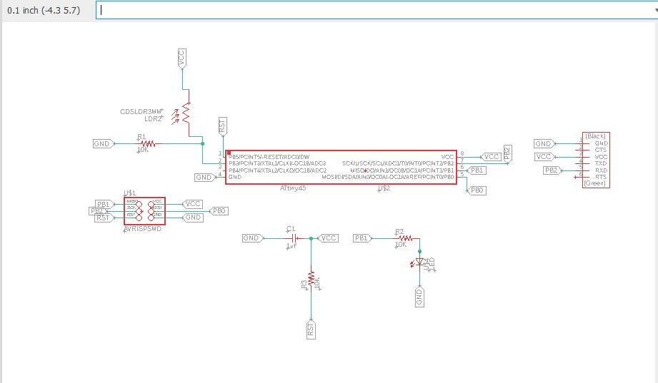
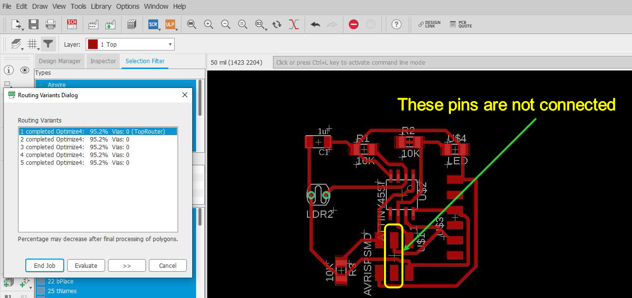
In schematic I connected both the pins but in board they does not come out, While giving labelling it is important to check they are connected or not by using ERC command.So in this case MOSI and SCK are not connected thats why I was not able to program it.
Final Board on ATmega 328p
As we have to complete final project first ,I started work on final project Electronics Design and then I used Attiny 44 for LDR as input and Servo Motor as output.The schematic and Board for this You can check in Week 12 Output Devices as with this board , I dint work on input devices.
I also design this board on Attiny 44 but when I uploaded the whole program of 4 LDR inputs and 2 servo motor. The memory of attiny was almost full.I also cant see the data of serial monitor with that then I moved to Atmega 328P.
Here you can see the Schematic of ATmega328p.
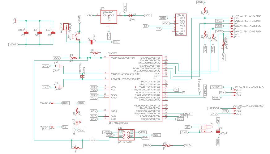

As per shatshakit I implement my design on it.For burning bootloder I gave 16 MHz oscillator and two 22uf capacitors and also pins for AVRISP(MISO MOSI RST GND VCC SCK).After Voltage Regulator, I gave diode so that current does not come back again to it.
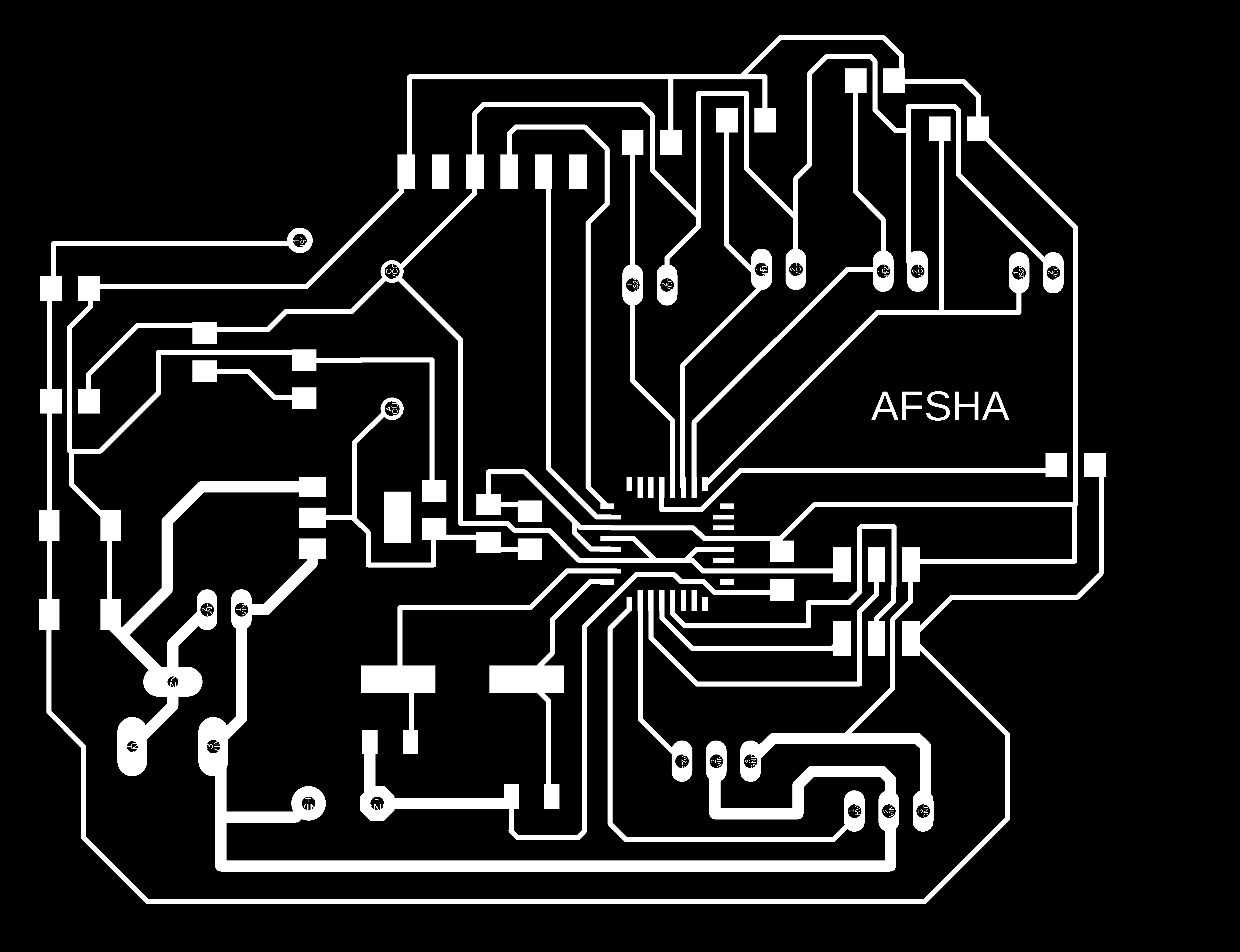
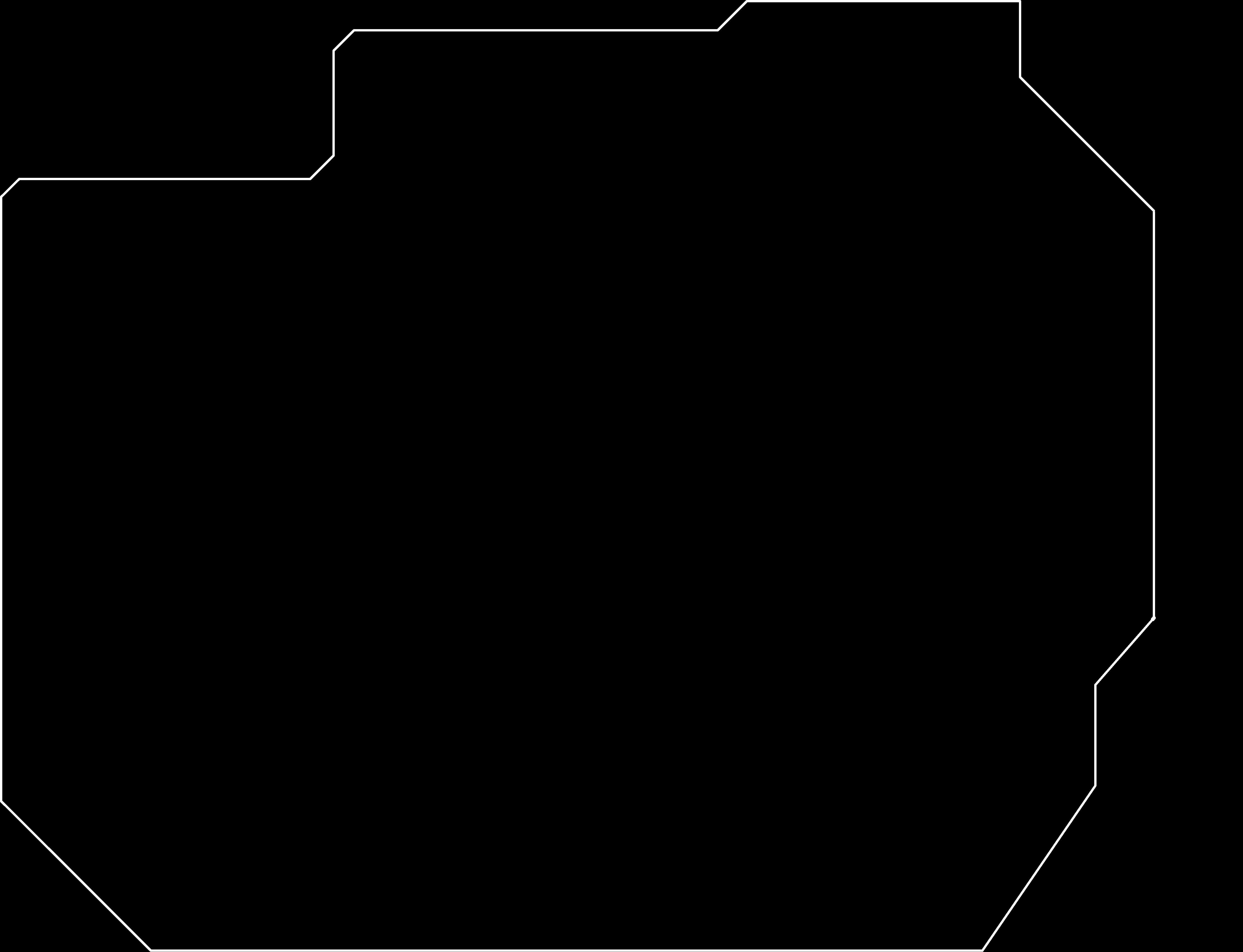
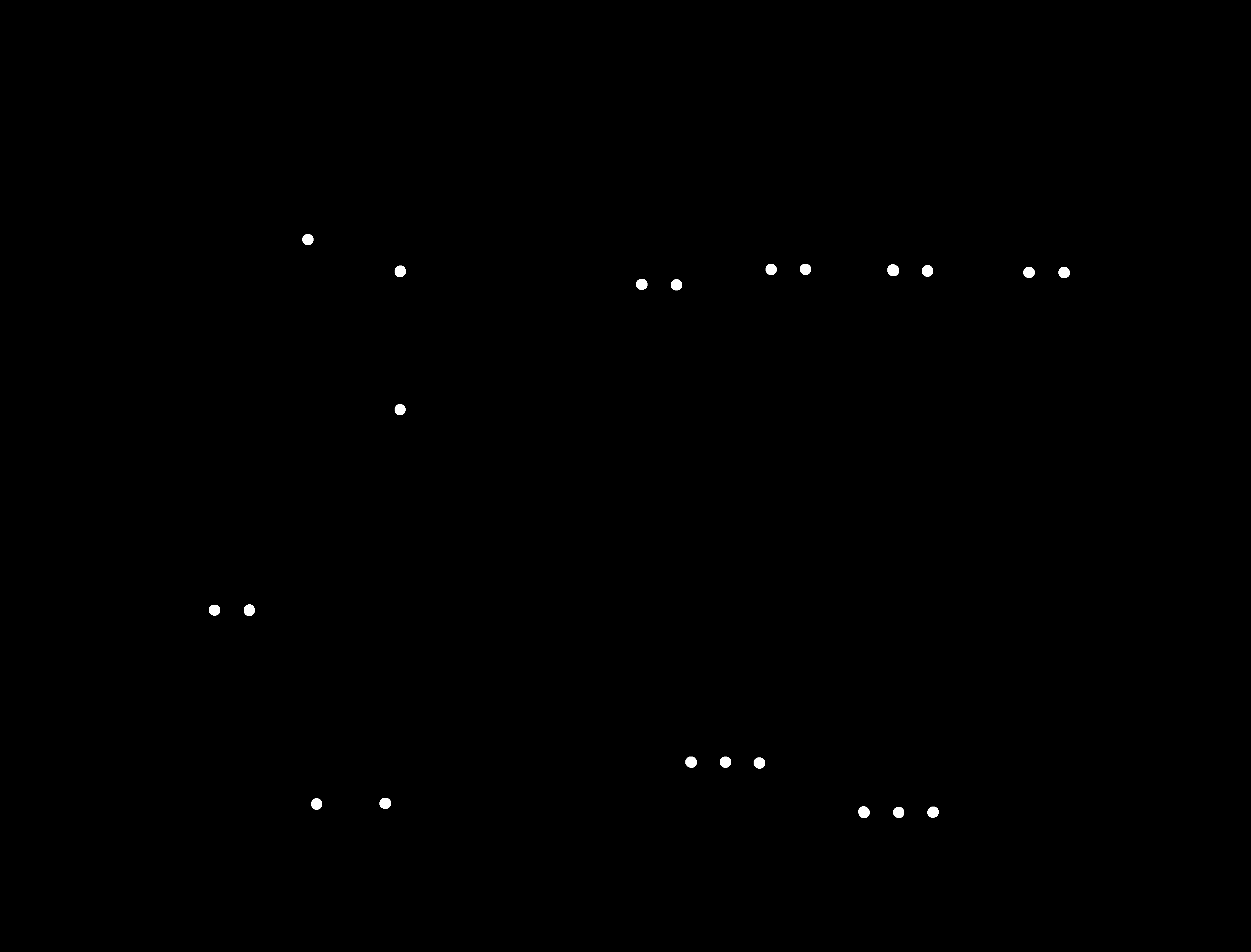

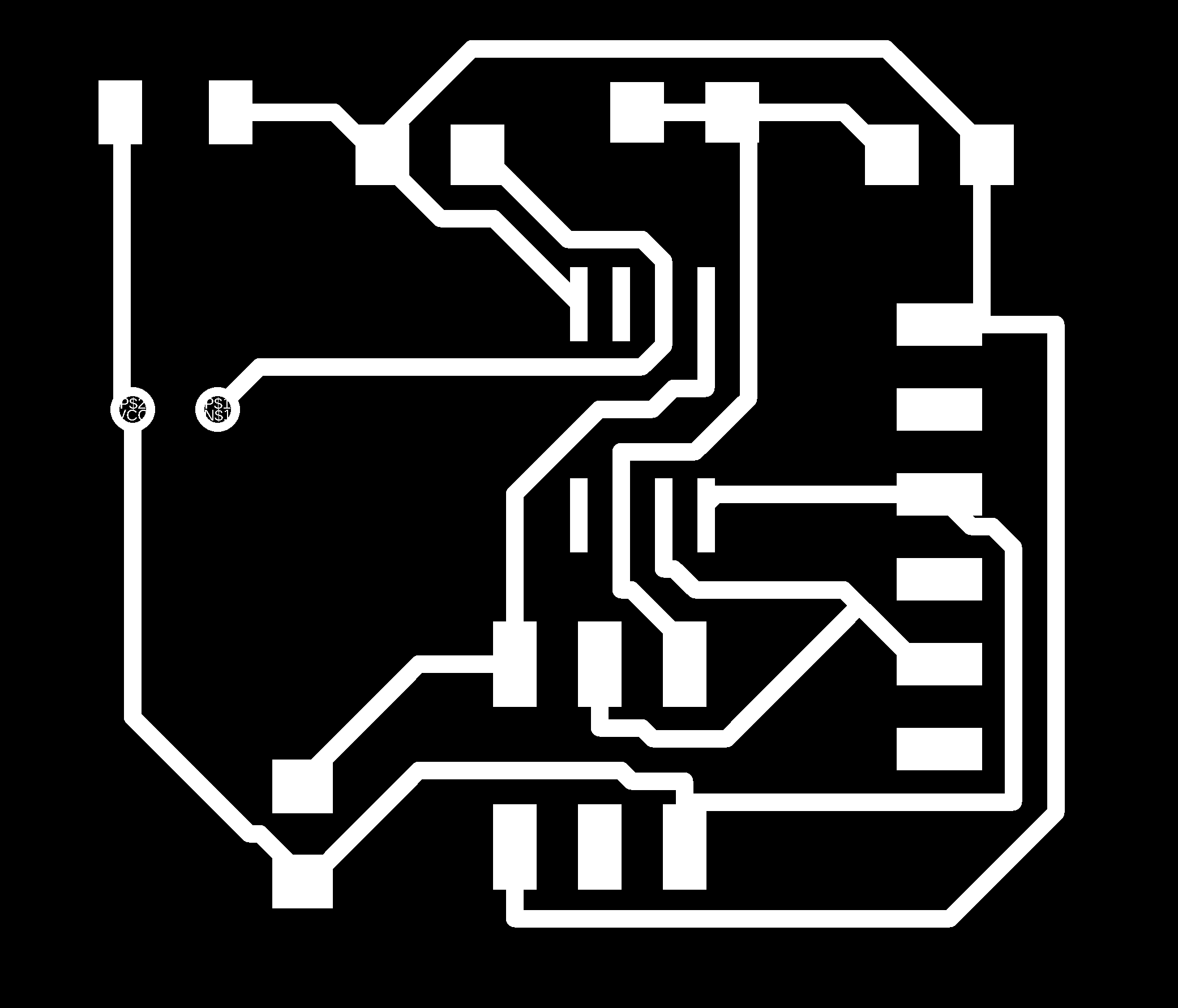
These are the PNG traces exported to go to milling process.
PCB MILLING
The process for PCB Milling was explained in Electronic Production week.
Here is the Video showing Milling of Final Baord PCB.
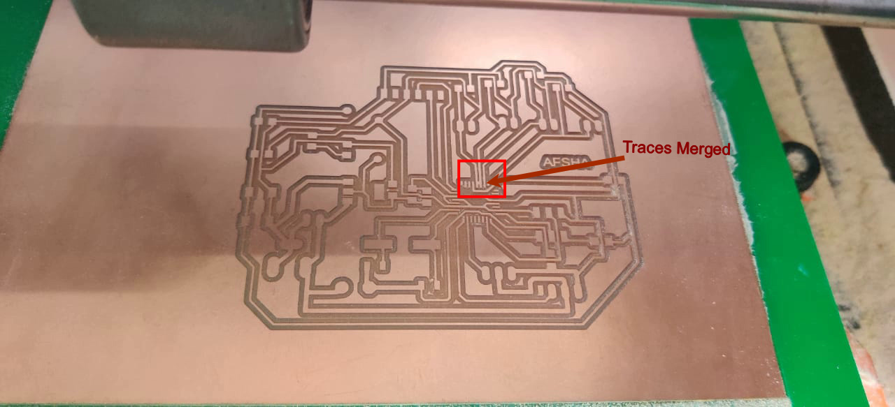
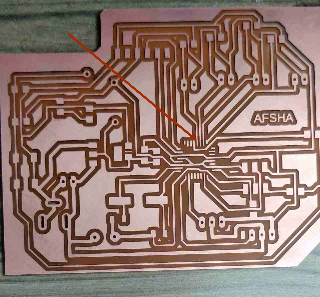
After Milling this is the PCB for Servo Motor and LDR.Everything come out fine except at one point on Atmega traces got shot.I used knife to cut the shot traces.
Soldering
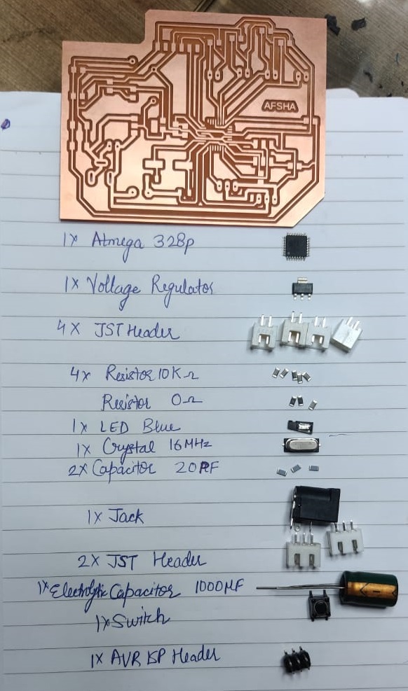
For soldering, I collect all the components and write it down.Below is the Image showing all the components.
Here is the video for soldering
After soldering the PCB is here.
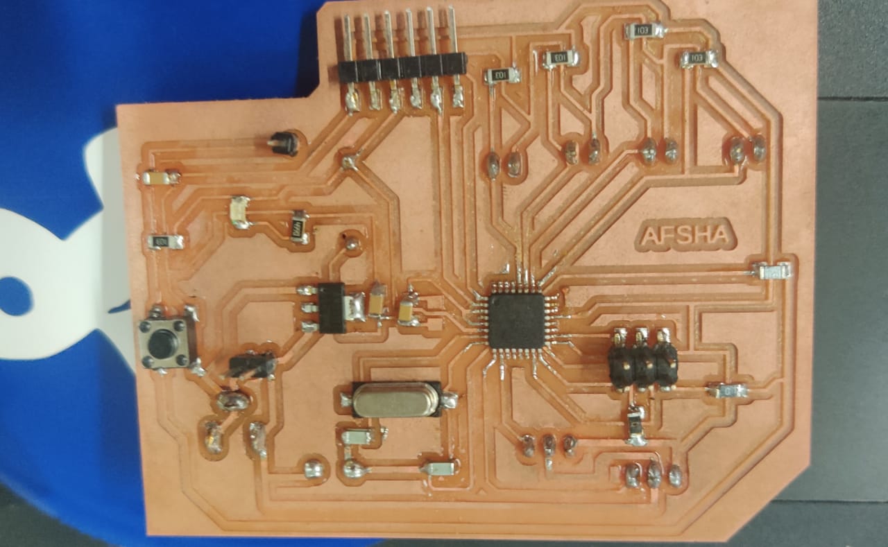
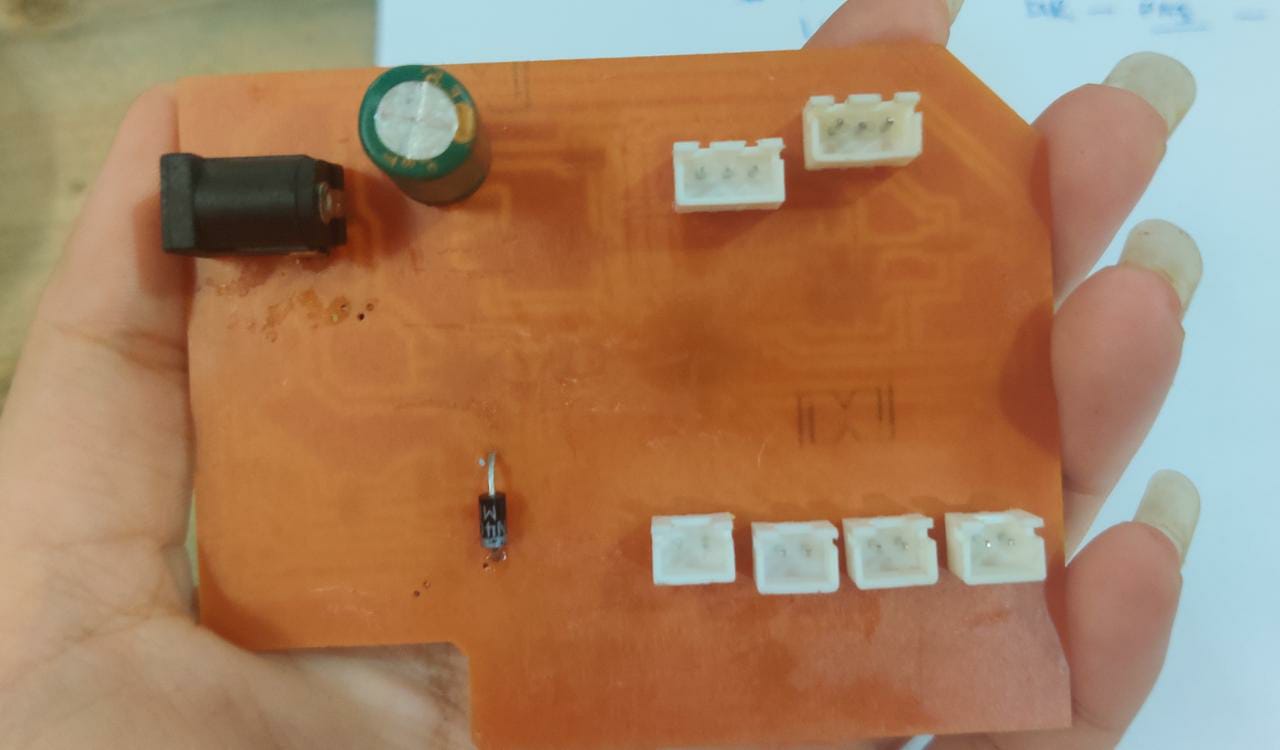
This is the backside of PCB.
LDR DATA ON SERIAL MONITOR
I used FTDI to TTL convertor for Serial Communication and connected RX,TX and GND of ATmega FTDI which I used 3 and 4 pin to TX and RX GND of convertor.Programm to See data on Serial Monitor
  #include "SoftwareSerial.h"
    #define RX   4   //TX pin of ATmega
    #define TX    3  //RX pin of ATmega
    SoftwareSerial mySerial(4,3);  //RX, TX

    int sensorPin = A5; // select the input pin for LDR

    int sensorValue = 0; // variable to store the value coming from the sensor
    void setup() {
      mySerial.begin(9600); //sets serial port for communication
    }
    void loop() {
      sensorValue = analogRead(sensorPin); // read the value from the sensor
      mySerial.println(sensorValue); //prints the values coming from the sensor on the screen

      delay(1000);
    }
Description of DS3231 Real Time Clock
The DS3231 is a low-cost, extremely accurate I2C real-time clock (RTC) with an integrated temperaturecompensated crystal oscillator (TCXO) and crystal. The device incorporates a battery input, and maintains accurate timekeeping when main power to the device is interrupted. The integration of the crystal resonator enhances the long-term accuracy of the device as well as reduces the piece-part count in a manufacturing line. The DS3231 is available in commercial and industrial temperature ranges, and is offered in a 16-pin, 300-mil SO package.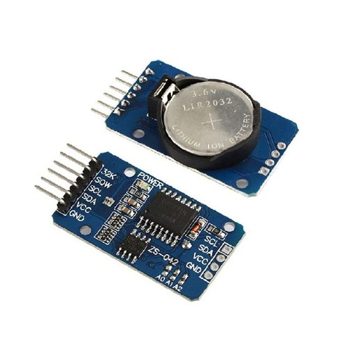
For this I have used SDA and SCL ie A4 and A5 pin of ATmega for I2C communication.
In case of Attiny 44 it does not support library for ds3231 RTC, I was not able to program pcb of Attiny44.
Programm to See data on Serial Monitor
  #include "Wire.h"
    #include "RTClib.h"
    #include "SoftwareSerial.h"
    #define RX   4   //TX pin of ATmega
    #define TX    3  //RX pin of ATmega
    SoftwareSerial mySerial(4,3);  //RX, TX

    RTC_DS3231 rtc;

    char daysOfTheWeek[7][12] = {"Sunday", "Monday", "Tuesday", "Wednesday", "Thursday", "Friday", "Saturday"};

    void setup ()
    {
      mySerial.begin(9600);
      delay(3000); // wait for console opening

      if (! rtc.begin()) {
        mySerial.println("Couldn't find RTC");
        while (1);
      }

      if (rtc.lostPower()) {
        mySerial.println("RTC lost power, lets set the time!");

      // Comment out below lines once you set the date & time.
        // Following line sets the RTC to the date & time this sketch was compiled
        rtc.adjust(DateTime(F(__DATE__), F(__TIME__)));

        // Following line sets the RTC with an explicit date & time
        // for example to set January 27 2017 at 12:56 you would call:
        // rtc.adjust(DateTime(2017, 1, 27, 12, 56, 0));
      }
    }

    void loop ()
    {
        DateTime now = rtc.now();

        mySerial.println("Current Date & Time: ");
        mySerial.print(now.year(), DEC);
        mySerial.print('/');
        mySerial.print(now.month(), DEC);
        mySerial.print('/');
        mySerial.print(now.day(), DEC);
        mySerial.print(" (");
        mySerial.print(daysOfTheWeek[now.dayOfTheWeek()]);
        mySerial.print(") ");
        mySerial.print(now.hour(), DEC);
        mySerial.print(':');
        mySerial.print(now.minute(), DEC);
        mySerial.print(':');
        mySerial.print(now.second(), DEC);
        mySerial.println();

        mySerial.println("Unix Time: ");
        mySerial.print("elapsed ");
        mySerial.print(now.unixtime());
        mySerial.print(" seconds/");
        mySerial.print(now.unixtime() / 86400L);
        mySerial.println(" days since 1/1/1970");

        // calculate a date which is 7 days & 30 seconds into the future
        DateTime future (now + TimeSpan(7,0,0,30));

        mySerial.println("Future Date & Time (Now + 7days & 30s): ");
        mySerial.print(future.year(), DEC);
        mySerial.print('/');
        mySerial.print(future.month(), DEC);
        mySerial.print('/');
        mySerial.print(future.day(), DEC);
        mySerial.print(' ');
        mySerial.print(future.hour(), DEC);
        mySerial.print(':');
        mySerial.print(future.minute(), DEC);
        mySerial.print(':');
        mySerial.print(future.second(), DEC);
        mySerial.println();

        mySerial.println();
        delay(1000);
    }
Group Assignment
Measuring Analog Signal:
We measured the analog signal by connecting both the probe of oscilloscope to Gnd and Vcc pin of dc motor and rotated the shaft manually. The motor is generally consisdered as the output device but if we give rotation to motor manually then an induced voltage can be seen on the oscilloscope. Since the construction of the motor and generator are similar so we used motor as the input device.
Measuring Digital Signal:
We uploaded Blink code on the UNO board and we observed the pulse signal.Above are the results for the same.

