Networking and Communication
##ASSIGNMENT
>>>>individual assignment:
design, build, and connect wired or wireless node(s) with network or bus addresses
>>>>group assignment:
send a message between two projects
I2C Protocol
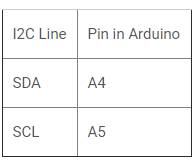
I2C stands for inter integrated circuit. I2C requires only two wires connecting all peripherals to microcontroller.I2C requires two wires SDA (serial data line) and SCL (serial clock line) to carry information between devices. It is a master to slave communication protocol. Each slave has a unique address. Master device sends the address of the target slave device and read/write flag. The address is match any slave device that device is ON, remaining slave devices are disable mode. Once the address is match communication proceed between master and that slave device and transmitting and receiving the data.
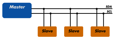
Source: Sparkfun
SPI Protocol
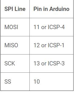
SPI stands for serial peripheral interface. It is one of the serial communication protocol developed by Motorola. Some times SPI protocol is also called a 4-wire protocol. It requires four wires MOSI, MISO, SS, and SCLK.SPI protocol used to communicate the master and slave devices. The master first configures the clock using a frequency. The master then selects the particular slave device for communication by pulling the chip select button. That particular device is selected and starts the communication between master and that particular slave. The master select only one slave at a time. It is full duplex communication protocol. Not limited to 8 bit words in the case of bit transferring.

Source: Electronicshub
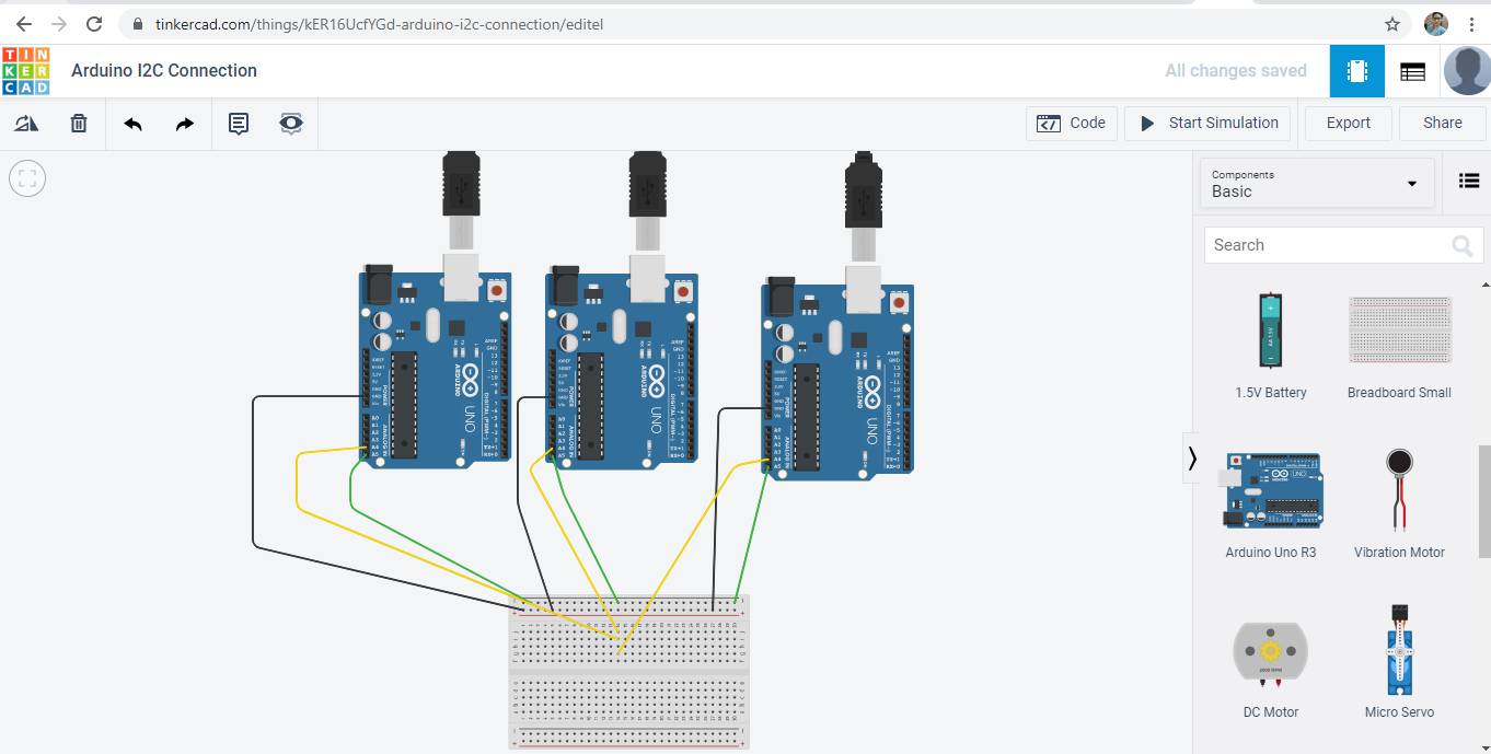
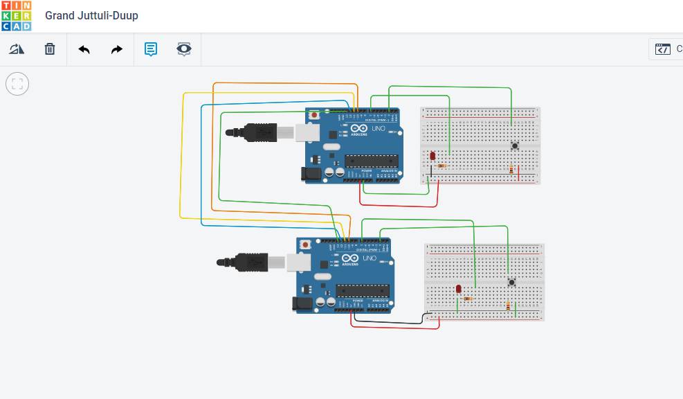
Communication of Arduino with two other Arduino board
I followed this tutorial for this wired communication. I connected three arduino using I2C communication protocal, in which A4 A5 and GND of arduino is connected to breadboard as SDA(yellow) and SCL(green).
Code for Master:
    #include "Wire.h"

        void setup()
        {
          Wire.begin();
        }

        void loop()
        {
          Wire.beginTransmission(1);
          Wire.write('H');
          Wire.endTransmission();

          delay(500);

          Wire.beginTransmission(1);
          Wire.write('L');
          Wire.endTransmission();

          delay(500);

          Wire.beginTransmission(2);
          Wire.write('H');
          Wire.endTransmission();

          delay(500);

          Wire.beginTransmission(2);
          Wire.write('L');
          Wire.endTransmission();

          delay(500);
        }
Code for Slave 1
    #include "Wire.h"

        const byte slaveId = 1;

        void setup()
        {
          Wire.begin(slaveId);
          Wire.onReceive(receiveEvent);

          pinMode(13,OUTPUT);
          digitalWrite(13,LOW);
        }

        void loop()
        {
        }

        void receiveEvent(int howMany)
        {
          char inChar;

          while(Wire.available() > 0)
          {
            inChar = Wire.read();

            if (inChar == 'H')
            {
              digitalWrite(13, HIGH);
            }
            else if (inChar == 'L')
            {
              digitalWrite(13, LOW);
            }
          }
        }
Code for Slave 2
    #include "Wire.h"

        const byte slaveId = 2;

        void setup()
        {
          Wire.begin(slaveId);
          Wire.onReceive(receiveEvent);

          pinMode(13,OUTPUT);
          digitalWrite(13,LOW);
        }

        void loop()
        {
        }

        void receiveEvent(int howMany)
        {
          char inChar;

          while(Wire.available() > 0)
          {
            inChar = Wire.read();

            if (inChar == 'H')
            {
              digitalWrite(13, HIGH);
            }
            else if (inChar == 'L')
            {
              digitalWrite(13, LOW);
            }
          }
        }
#include "Wire.h"
const byte slaveId = 1;
void setup()
{
Wire.begin(slaveId);
Wire.onReceive(receiveEvent);
pinMode(13,OUTPUT);
digitalWrite(13,LOW);
}
void loop()
{
}
void receiveEvent(int howMany)
{
char inChar;
while(Wire.available() > 0)
{
inChar = Wire.read();
if (inChar == 'H')
{
digitalWrite(13, HIGH);
}
else if (inChar == 'L')
{
digitalWrite(13, LOW);
}
}
}
#include "Wire.h"
const byte slaveId = 2;
void setup()
{
Wire.begin(slaveId);
Wire.onReceive(receiveEvent);
pinMode(13,OUTPUT);
digitalWrite(13,LOW);
}
void loop()
{
}
void receiveEvent(int howMany)
{
char inChar;
while(Wire.available() > 0)
{
inChar = Wire.read();
if (inChar == 'H')
{
digitalWrite(13, HIGH);
}
else if (inChar == 'L')
{
digitalWrite(13, LOW);
}
}
}
I referred the code from that tutorial only.
SPI COMMUNICATION WITH TWO ARDUINO
A SPI has a master/Slave communication by using four lines. A SPI can have only one master and can have multiple slaves. A master is usually a microcontroller and the slaves can be a microcontroller, sensors, ADC, DAC, LCD etc.
I used this tutrial from Circuit digest for SPI communication.
In this circuit led of master Arduino board blink when we button on slave is pressed
Code for MASTER
#include "SPI.h"
  #define LED 7
  #define ipbutton 2
  int buttonvalue;
  int x;
  void setup (void)

  {
    Serial.begin(115200);                   //Starts Serial Communication at Baud Rate 115200

    pinMode(ipbutton,INPUT);                //Sets pin 2 as input
    pinMode(LED,OUTPUT);                    //Sets pin 7 as Output

    SPI.begin();                            //Begins the SPI commnuication
    SPI.setClockDivider(SPI_CLOCK_DIV8);    //Sets clock for SPI communication at 8 (16/8=2Mhz)
    digitalWrite(SS,HIGH);                  // Setting SlaveSelect as HIGH (So master doesnt connnect with slave)
  }

  void loop(void)
  {
    byte Mastersend,Mastereceive;

    buttonvalue = digitalRead(ipbutton);   //Reads the status of the pin 2

    if(buttonvalue == HIGH)                //Logic for Setting x value (To be sent to slave) depending upon input from pin 2
    {
      x = 1;
    }
    else
    {
      x = 0;
    }

    digitalWrite(SS, LOW);                  //Starts communication with Slave connected to master

    Mastersend = x;
    Mastereceive=SPI.transfer(Mastersend); //Send the mastersend value to slave also receives value from slave

    if(Mastereceive == 1)                   //Logic for setting the LED output depending upon value received from slave
    {
      digitalWrite(LED,HIGH);              //Sets pin 7 HIGH
      Serial.println("Master LED ON");
    }
    else
    {
     digitalWrite(LED,LOW);               //Sets pin 7 LOW
     Serial.println("Master LED OFF");
    }
    delay(1000);
  }
Code for SLAVE
    #include "SPI.h"
      #define LEDpin 7
      #define buttonpin 2
      volatile boolean received;
      volatile byte Slavereceived,Slavesend;
      int buttonvalue;
      int x;
      void setup()

      {
        Serial.begin(115200);

        pinMode(buttonpin,INPUT);               // Setting pin 2 as INPUT
        pinMode(LEDpin,OUTPUT);                 // Setting pin 7 as OUTPUT
        pinMode(MISO,OUTPUT);                   //Sets MISO as OUTPUT (Have to Send data to Master IN

        SPCR |= _BV(SPE);                       //Turn on SPI in Slave Mode
        received = false;

        SPI.attachInterrupt();                  //Interuupt ON is set for SPI commnucation

      }

      ISR (SPI_STC_vect)                        //Inerrrput routine function
      {
        Slavereceived = SPDR;         // Value received from master if store in variable slavereceived
        received = true;                        //Sets received as True
      }

      void loop()
      { if(received)                            //Logic to SET LED ON OR OFF depending upon the value recerived from master
         {
            if (Slavereceived==1)
            {
              digitalWrite(LEDpin,HIGH);         //Sets pin 7 as HIGH LED ON
              Serial.println("Slave LED ON");
            }else
            {
              digitalWrite(LEDpin,LOW);          //Sets pin 7 as LOW LED OFF
              Serial.println("Slave LED OFF");
            }

            buttonvalue = digitalRead(buttonpin);  // Reads the status of the pin 2

            if (buttonvalue == HIGH)               //Logic to set the value of x to send to master
            {
              x=1;

            }else
            {
              x=0;
            }

        Slavesend=x;
        SPDR = Slavesend;                           //Sends the x value to master via SPDR
        delay(1000);
      }
      }
I referred the code from Circuitdigest tutorial only.
Work After Lockdown
As performed above the simulation of master arduino and two arduino. I tried it on Arduino board and you can see the video in which with the help of master, LED is blinking on two slave Arduino board.The process of I2C communication explained above.
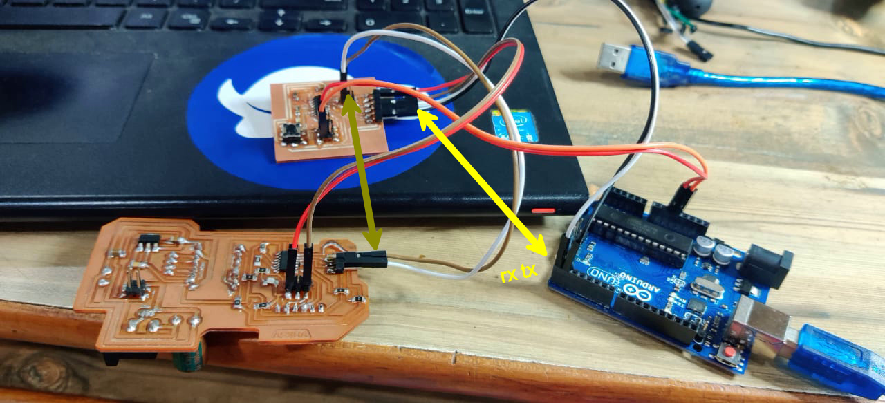
Networking between Two Boards
I have made Hello Echo Board in Electronics Design Week in that board I gave FTDI and two other RX and TX pin for serial communication and other board I used was my output device board for stepper motor.
In this video you can see I have connected RX and TX of one board to TX and RX of Hello Echo Board and for Serial monitor I used arduino as FTDI for communication and connected the RX and TX pin of arduino to Hello Echo Board as there were two RX,TX present in it.
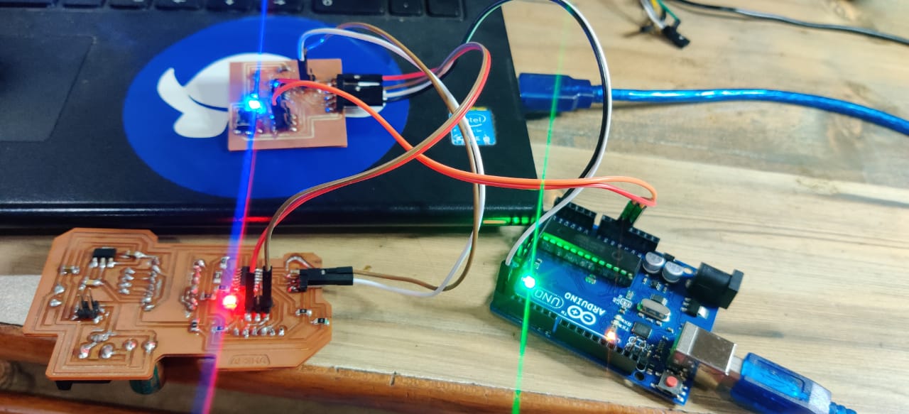
When I enter 1 on the serial monitor, the Red LED on one of the Board blink and when I enter 2 on serial monitor the Blue LED blink.
I did not try I2C communication because for that I have to include the sda scl pins in board thats why I only tried Serial communication in which I used Arduino as Ftddi
Code for Node 1:
    #include "SoftwareSerial.h"
    #define node '1' // defined bridge board address 0
    const int rx=0;
    const int tx=1;
    //int node=48;    // node number
    //int x=0;

    // the setup function runs once when you press reset or power the board
    SoftwareSerial mySerial(rx, tx);

    void setup() {
      // initialize digital pin 13 as an output.
       mySerial.begin(9600);
      pinMode(8, OUTPUT);
      digitalWrite(8, HIGH);
    }

    // the loop function runs over and over again forever
    void loop()
    {
      if(mySerial.available() > 0)

      {
        //mySerial.print("here");
        int x=mySerial.read();
        delay(1000);
       // mySerial.print(x);

      if (x==node)
        {
        digitalWrite(8, LOW);   // turn the LED on (HIGH is the voltage level)
        delay(500);
        digitalWrite(8, HIGH);
        delay(500);

            }
      }
    }
Code for Node 2
    #include "SoftwareSerial.h"
    #define node '2' // defined bridge board address 0
    const int rx=0;
    const int tx=1;
    //int node=48;    // node number
    //int x=0;

    // the setup function runs once when you press reset or power the board
    SoftwareSerial mySerial(rx, tx);

    void setup() {
      // initialize digital pin 13 as an output.
       mySerial.begin(9600);
      pinMode(7, OUTPUT);
      digitalWrite(7, HIGH);
    }

    // the loop function runs over and over again forever
    void loop()
    {
      if(mySerial.available() > 0)

      {
        //mySerial.print("here");
        int x=mySerial.read();
        delay(1000);
       // mySerial.print(x);

      if (x==node)
        {
        digitalWrite(7, LOW);   // turn the LED on (HIGH is the voltage level)
        delay(500);
        digitalWrite(7, HIGH);
        delay(500);

            }
      }
    }
In this code mySerial.available() command is used to Get the number of bytes (characters) available for reading from a software serial port. This is data that's already arrived and stored in the serial receive buffer.Two nodes are created to get the data for that node as it will get the data the LED will be Low.As initially we define it high.
Rx and Tx values on board should be mention correctly in Arduino program otherwise communication did not occur.
Group Assignment
For group assignment,We used final board of all three of us.We made Pulkits board as Node 1,Neeraj Sir board as Node 2 and mine as Node 3.Used the same code given above for blinking of LED.

