Computer Aided Design
This week I have to go through the bunch of 2D and 3D Design Softwares. As I am already aware and worked on various CAD tools. So this assignment was not that tough for me as website development. So I decided to start with some raster and vector-based tools. So here is a glimpse at the basics of Raster and Vector.
Raster Graphics
Raster images use bit maps to store information. This means a large file needs a large bitmap. The larger the image, the more disk space the image file will take up. As an example, a 640 x 480 image requires information to be stored for 307,200 pixels, while a 3072 x 2048 image (from a 6.3 Megapixel digital camera) needs to store information for a whopping 6,291,456 pixels. We use algorithms which compress images to help reduce these file sizes. Image formats like jpeg and gif are common compressed image formats. Scaling down these images is easy but enlarging a bitmap makes it pixelated or simply blurred. Hence for images which need to scaled to different sizes, we use vector graphics.File extensions: .BMP, .TIF, .GIF, .JPG
Vector Graphics
Making use of sequential commands or mathematical statements or programs which place lines or shapes in a 2-D or 3-D environment is referred to as Vector Graphics. Vector graphics are best for printing since it is composed of a series of mathematical curves. As a result vector graphics print crisply even when they are enlarged.In physics: A vector is something which has a magnitude and direction. In vector graphics, the file is created and saved as a sequence of vector statements. Rather than having a bit in the file for each bit of line drawing we use commands which describe series of points to be connected. AS a result a much smaller file is obtained.
File extensions : .SVG, .EPS, .PDF, .AI, .DXF Source : wikipedia
GIMP
First I Downloaded this sofware from this website
-
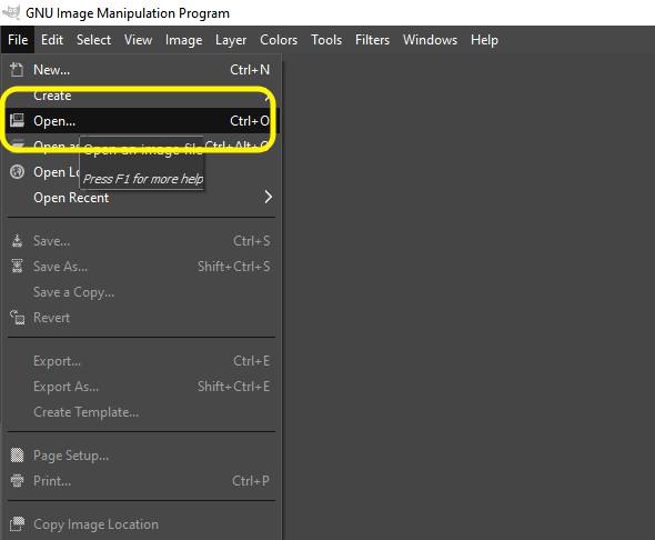
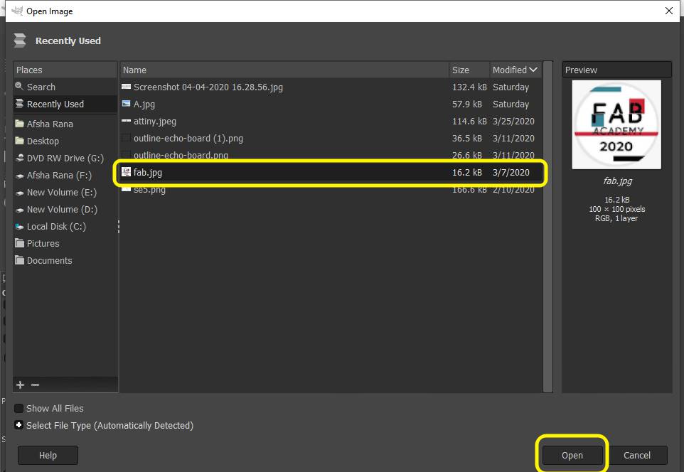
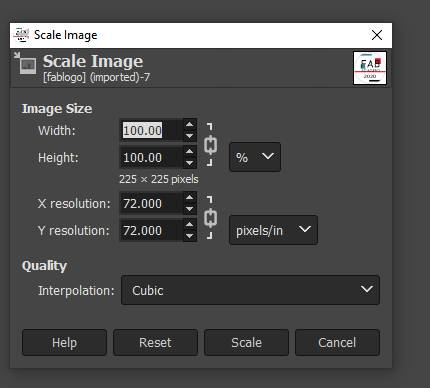
1. Open Image (Ctrl+O).
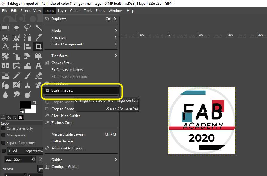
2. Image > Scale Image.
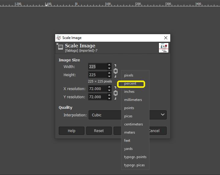
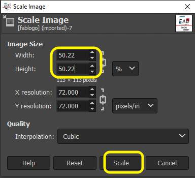
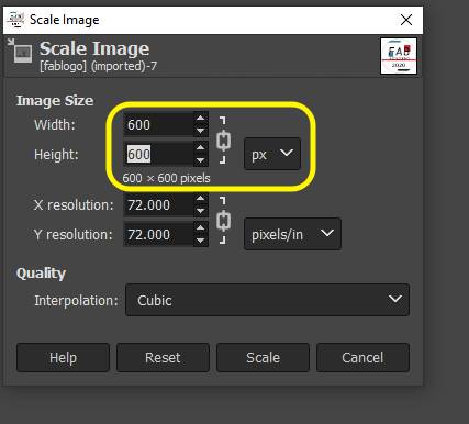
3.Size can be scale down or up,By percent,I reduced to 50%.
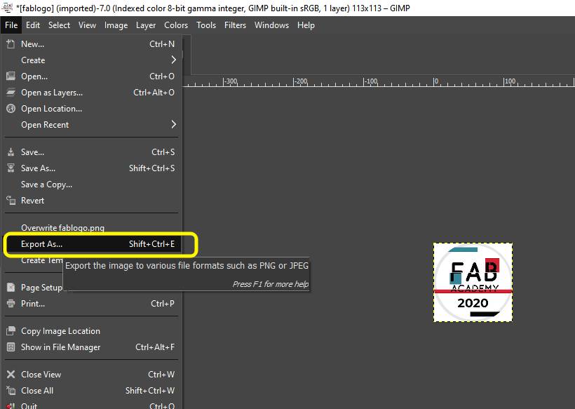
6. Quality: 70 or 90. You can also Click the "Show preview in image window" to see how it changes the image quality.
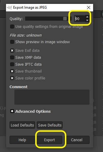
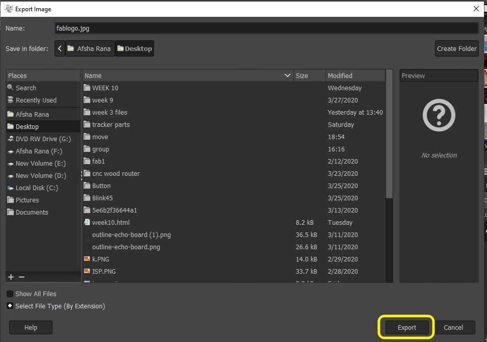
7. Export.
Inkscape
Inkscape is a free and open-source vector graphics editor. This software can be used to create or edit vector graphics such as illustrations, diagrams, line arts, charts, logos, business cards, book covers, icons, CD/DVD covers, and complex paintings. Inkscape's primary vector graphics format is Scalable Vector Graphics (SVG); however, many other formats can be imported and exported.
After watching this tutorial . I tried making some elements on inscape and in second attemp I made Donut on it.
The steps are as follows:
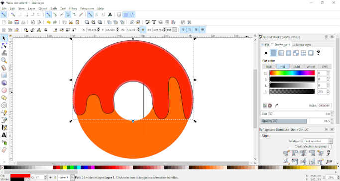
1.First take a circle from left bar make of suitable dimension by hold control and shift key.Enter the dia on upper bar and lock the dimension by clicking on lock icon.
2. Again draw the circle of small size and settle in between the circle by clicking on alignment bar
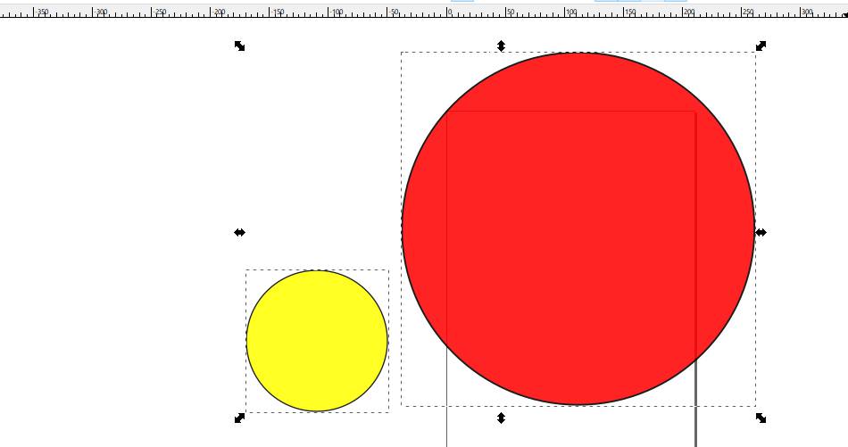
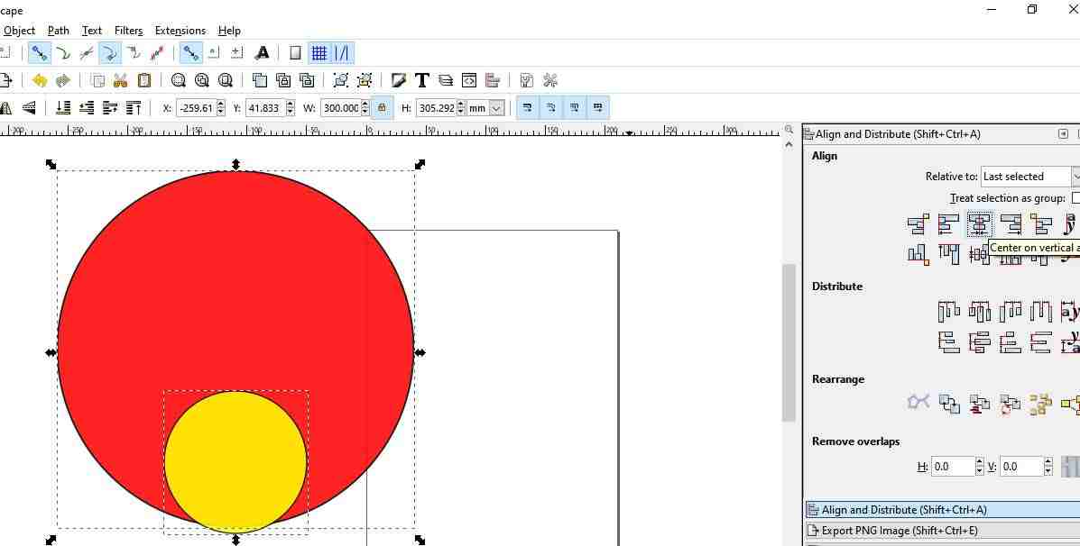
Align the circle vertically center.
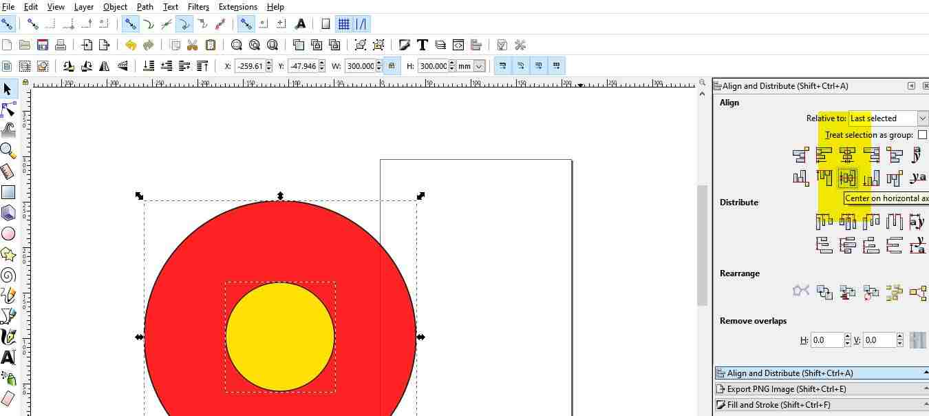
Align the circle vertically horizontal.
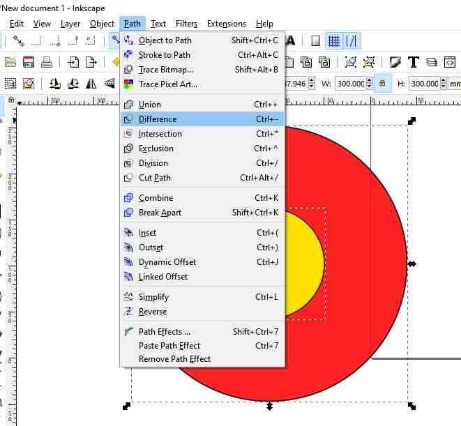
It comes in between and now go to path and lick on difference .
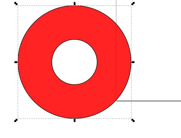
And substract it.
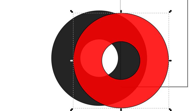
Duplicate the same shape by right click on it and give red color to it.
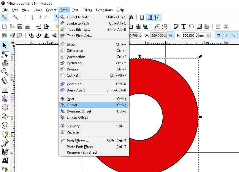
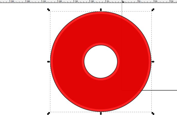
Now create some offset four time atleast on the duplicate one.
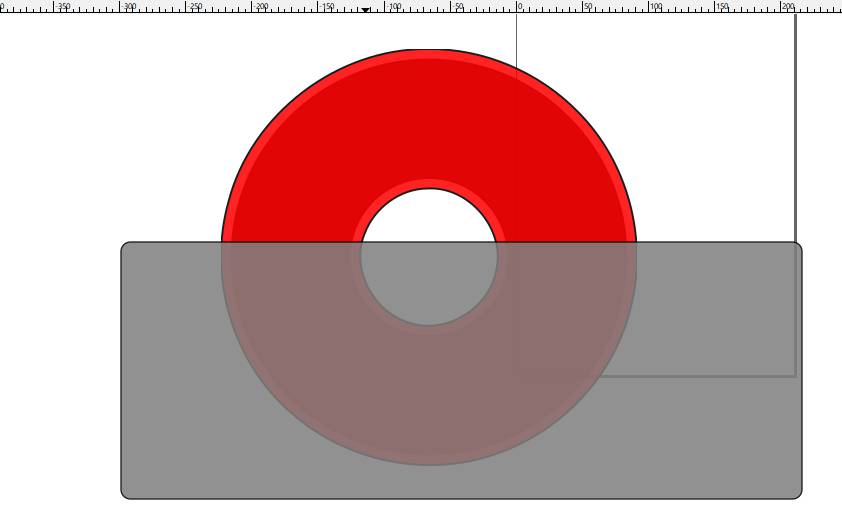
Make a rectangle half cover the portion.Substract it.
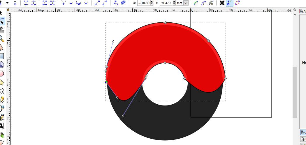
Select the half Circle and click on node on left bar and drag one node in between to lower position.
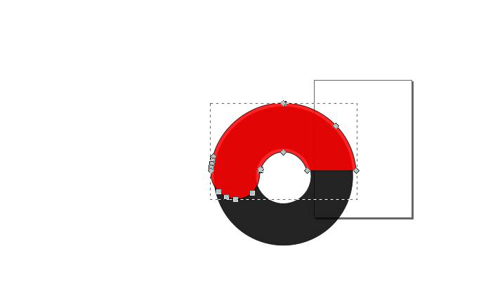
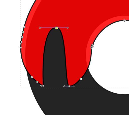
Now add extra nodes by click on add node option on top of left bar and lift the middle node upward to get the shape like this.
White portion is made by duplicating outer circle and using inset command approx 2o times to make it shorter.
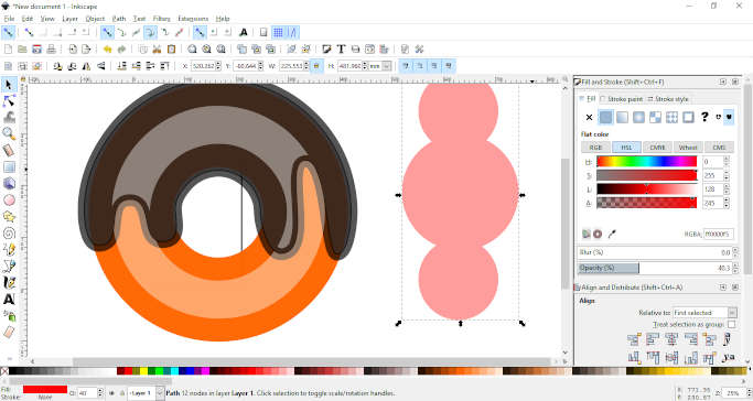
Make three circle and unite them. and after duplicating it four to five times drag ech one a little bit and drag it to position where we have to create a 3d effect bite, and substract it one by one.Chocolate froting are made by taking rectangle and drag outside point to middle giving the desired shape and copy paste at different positions.So our donut is ready.
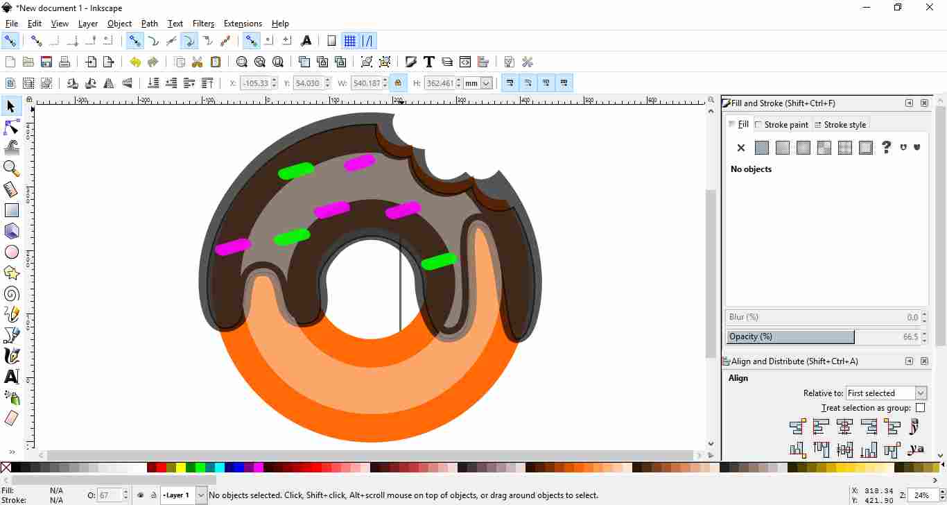
Last step is I exported it as jpg formats

NOTE : I have export the file direct into png so could not save the file in other format.
SOLID EDGE
3D Modeling Software which I used for making my project idea Sunflower Solar Tracker Design is Solid Edge St-9.
Solid Edge is a 3D CAD, parametric feature (history based) and synchronous technology solid modeling software. It runs on Microsoft Windows and provides solid modeling, assembly modelling and 2D orthographic view functionality for mechanical designers.
This is the paid sotware, I have licensed version in my lab.You can also download it from Siemens website as student.
I worked on Solid Edge Software to animate my project so I made parts to assemble it and after assembly, I did motion simulation and exported it in (.wmv) file and converted it in GIF format.
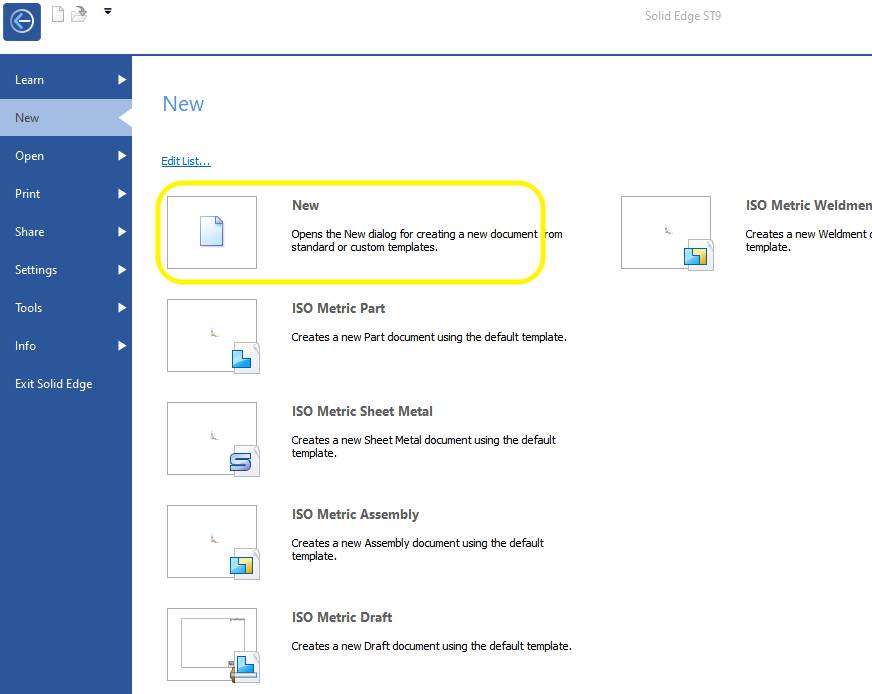
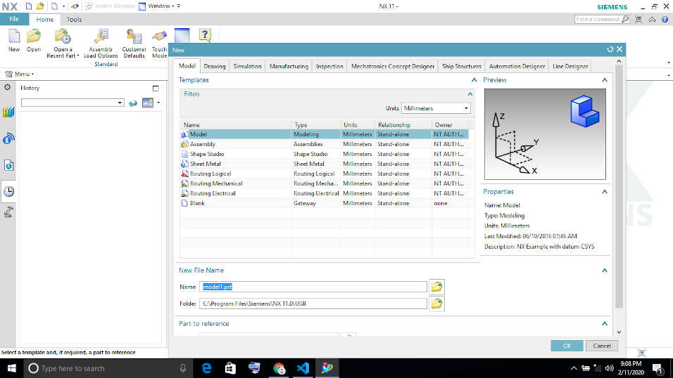
Click on New to start with solid edge.I am using St-09 version of solid Edge.
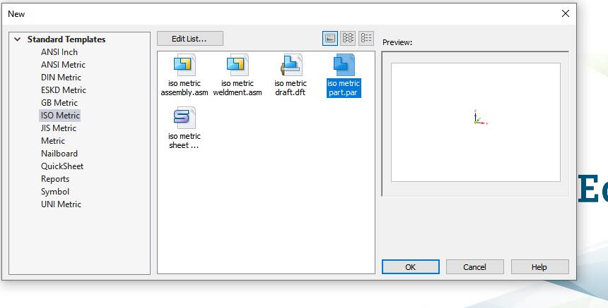
Select Isometric part.It is international standard for engineering drafting.
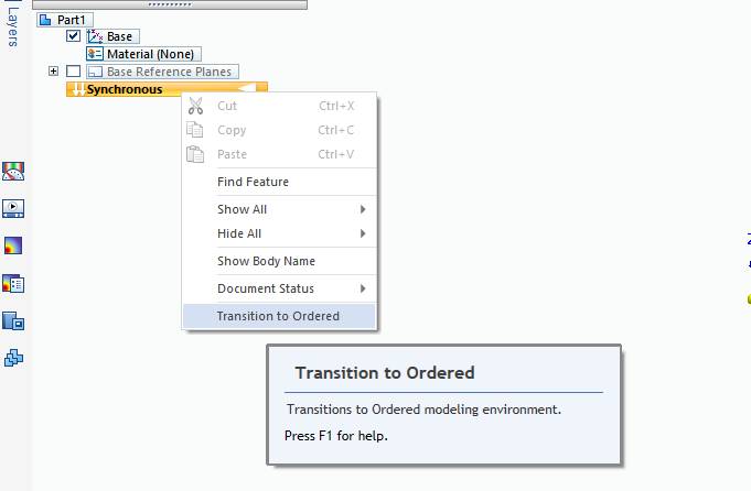
Then switch to ordered mode if you are new to modelling.
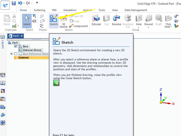
Start with sketchcommand
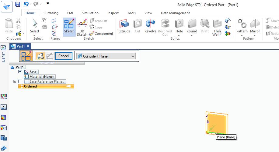
Select the plane for sketch as it will be 2D and workspace is in 3D.
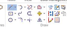
This is the Draw group having all sketch commands.
Parts of SOLAR TRACKER
BASE
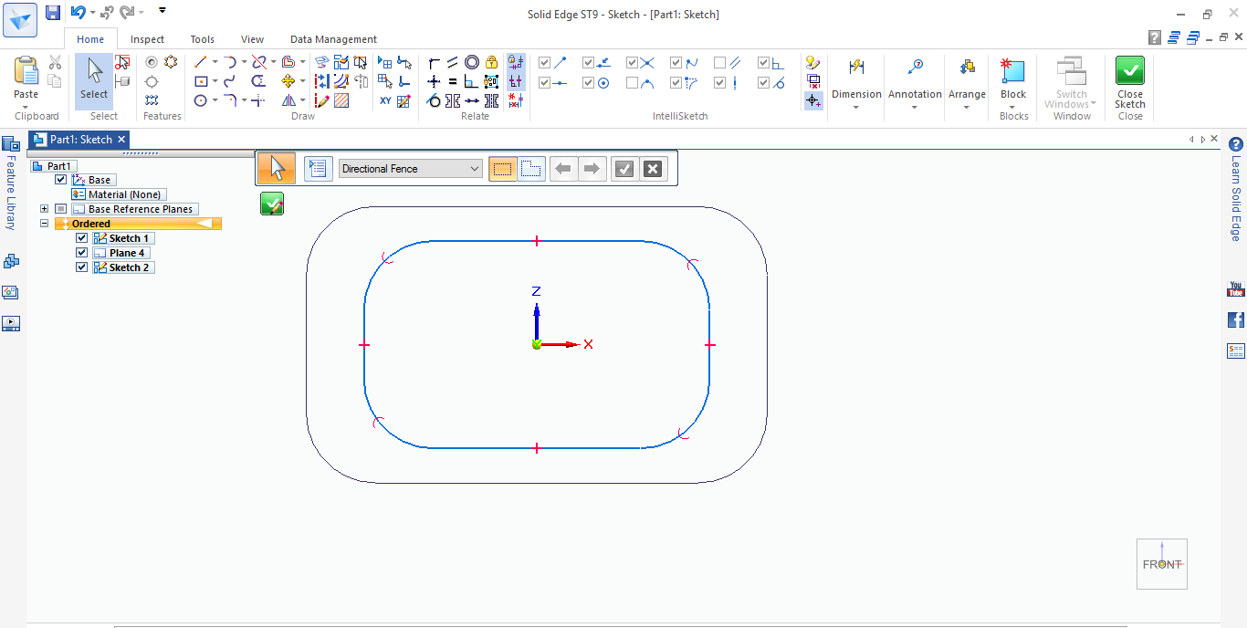
First draw one rectangle and fillet the corners.Then take another plane at a certain distance by using Datum plane.Draw econd rectangle as shown in figure with fillet.
And with loft command the two sketch has merged and converted into solid Base.
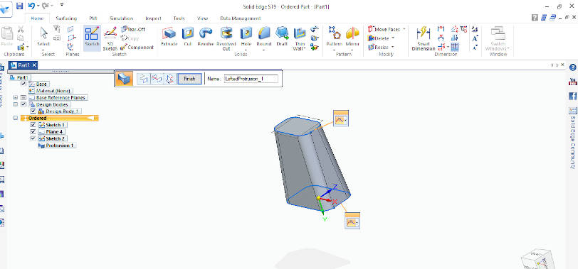
SUPPORT FOR PETALS
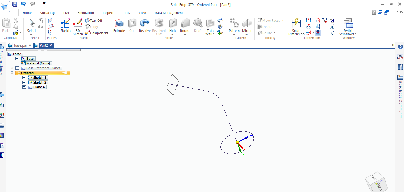
With the same process which is used earlier this time there is guide or path through which two sections are joined which are cirular.
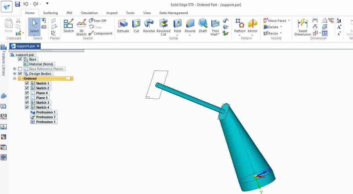
This is the final support.
SUNFLOWER PETALS
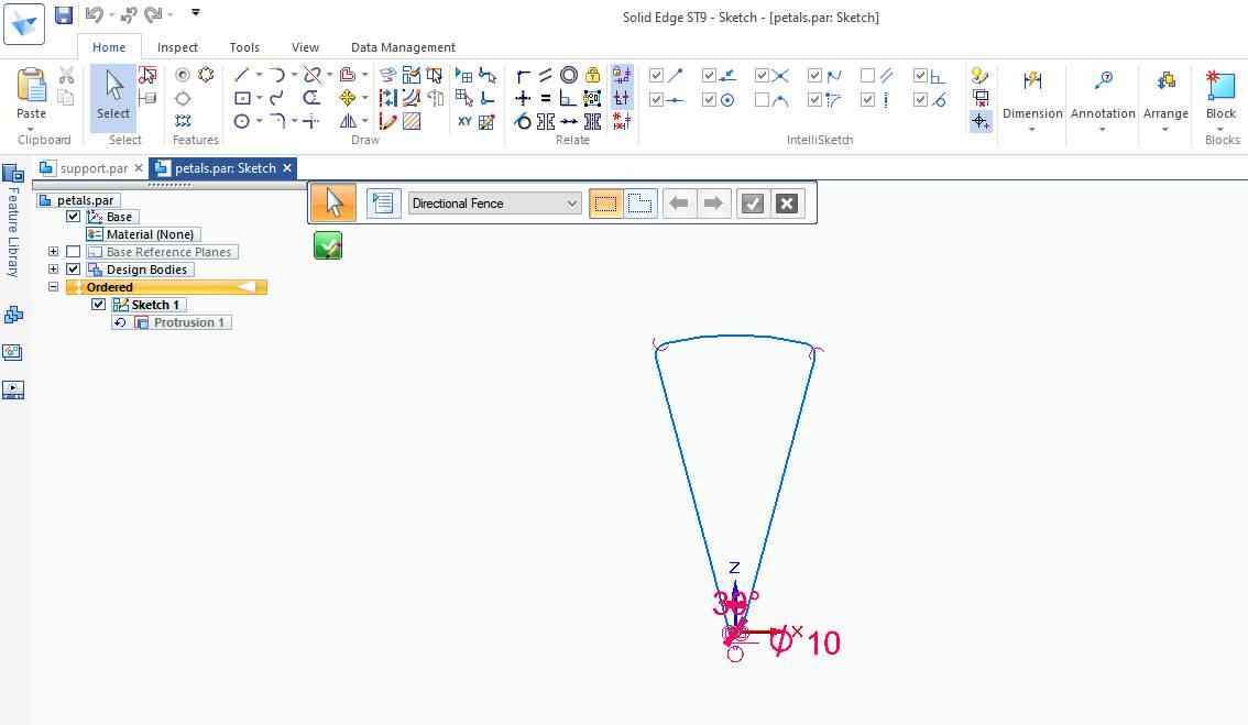
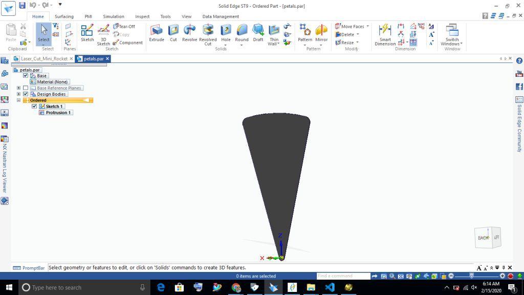
These are the petals made by using extrude command.
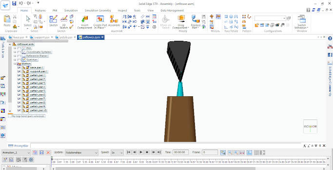
ASSEMBLY
For assembly open new template and select isometric assembly, Insert component one by one and all the parts got asemembled by using constraint (Align,touch,Center Align).
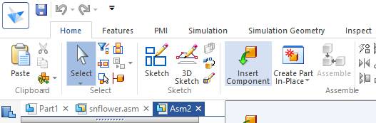
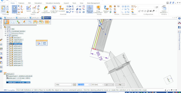
After slecting isometric assembly.This is the insert command which is used to insert parts.
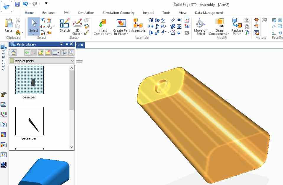
Select the part which is required from part library from the folder and drag the part to drop in workspace.
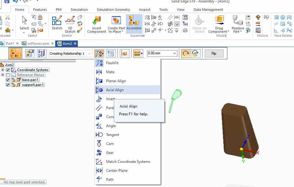
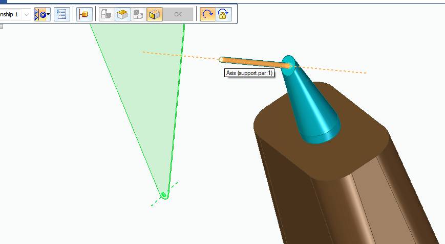
Now select the constrain align axis of both the parts.
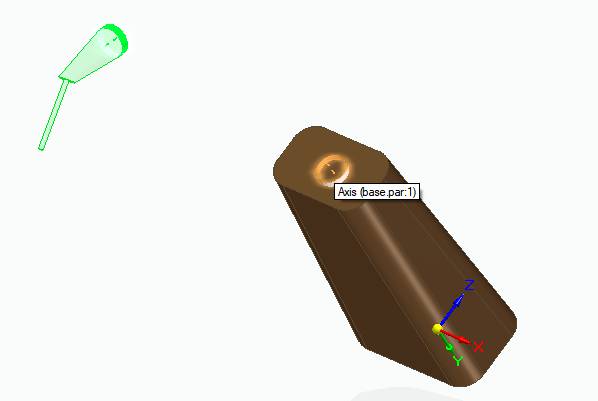
This is showing axis of both.
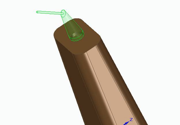
After pressing OK it will sit into the base.
Now drag the petals into the space.
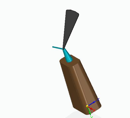
One of the petal set on the support.
In the similar manner follow for the remaining.
SIMULTION
In simulation,The simulation is done by giving rotational motors at each revolute joint and defining the angle ad speed of rotation.
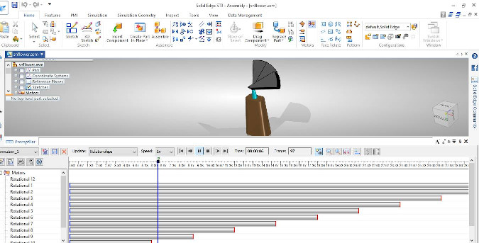
Final Project Animation
Smart Sunflower Solar Tracker
This is the assembly file of tracker which I have uploaded on Sketchfab.
The part files and STL file of Assembly can be downloaded
NX
NX is the most powerful, flexible, and innovative product development solution in the industry, NX for Design has the features, performance, and capabilities to help you get product to market faster than ever before.
I Used NX-11 which is a paid version, But I downloaded Crack version.
Analysis on Cantilever Beam.
Below are the steps:Step 1
First i made one L section Cantilever Beam by using sketch and extrude command.
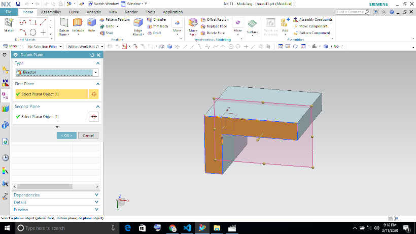
Step 2
Then for analysi,Go to the applicatiion tab and choose Pre and post option and then select new simulation and analysis option.
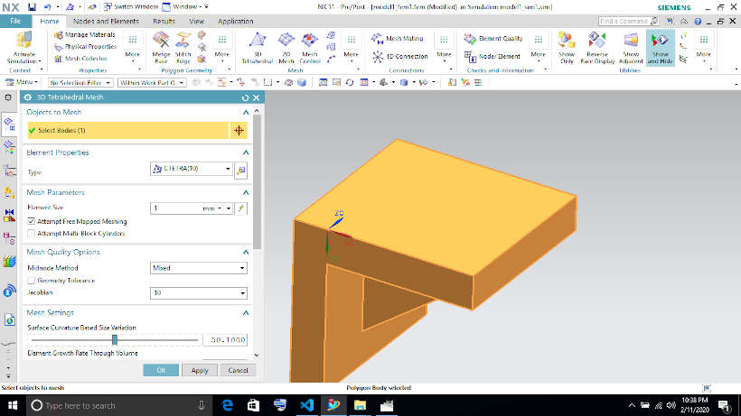
Step 3
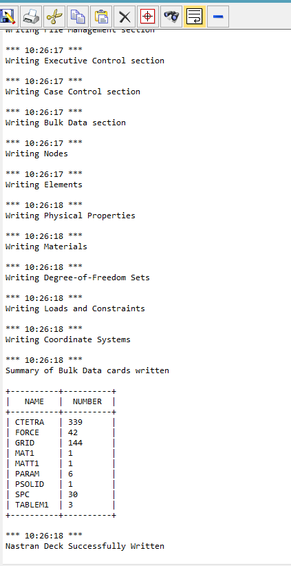
As for analysis first step is to do meshing(i did tetrahedral meshing).
Step 4
Then i made one wall fixed and gave fixed support to it.
Step 5
After that i choose Material type Aluminium.
Step 6
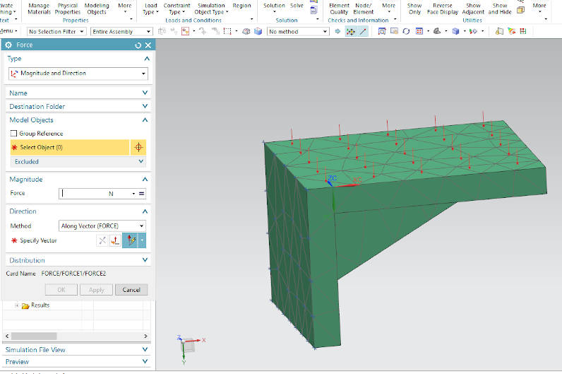
Then i applied Force of 2000N on cantilever Face.
Step 7
Then last option is to click on solve.These are the results showing deviation and displacement due to 2k Newton force on upper face.
Openscad
OpenSCAD is a free software application for creating solid 3D CAD (computer-aided design) objects. It is a script-only based modeller that uses its own description language; parts can be previewed, but it cannot be interactively selected or modified by mouse in the 3D view. I found this tutorial and made one part on it.
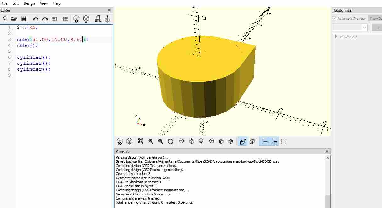
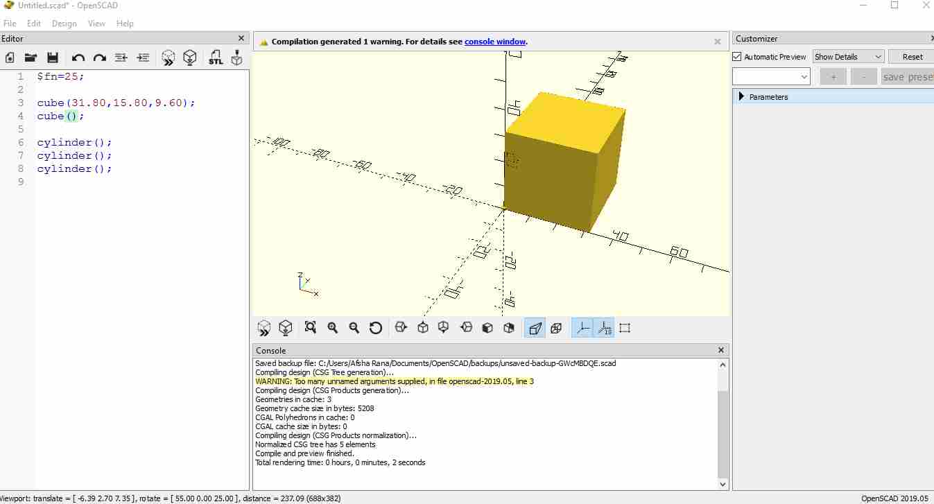
This is the cube which is made.
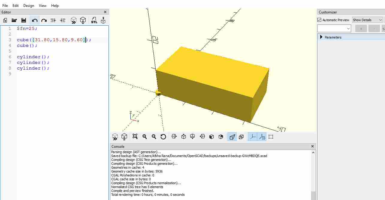
This is the cuboid.
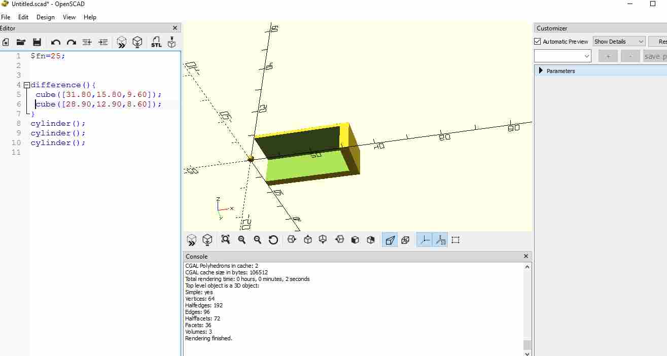
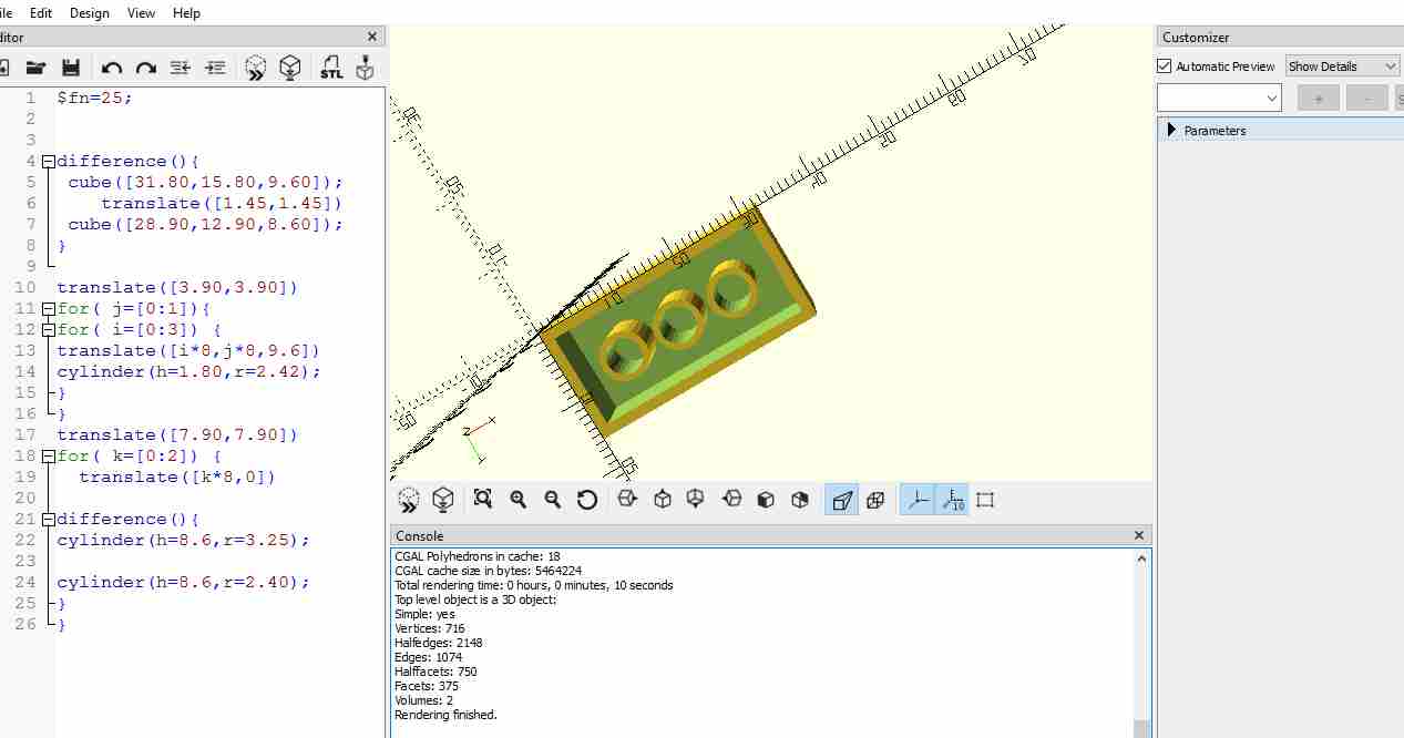
Now by using difference,substract the small cuboid from large one.
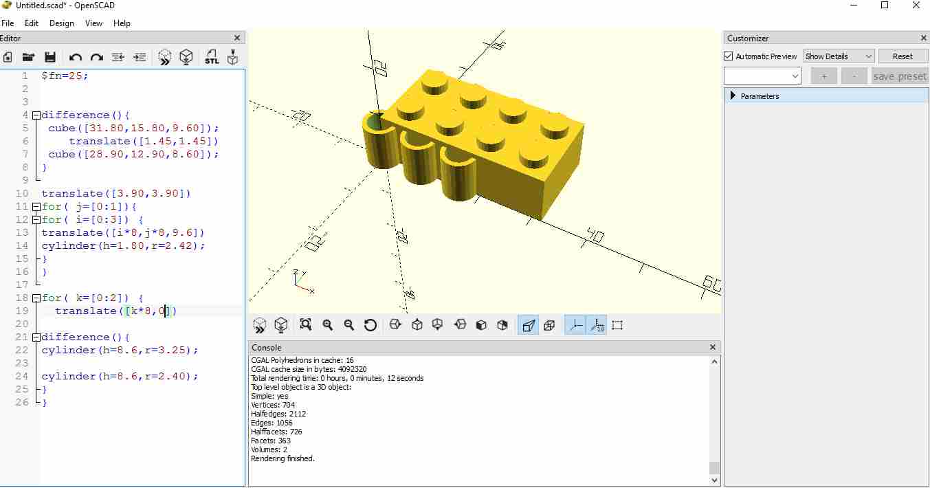
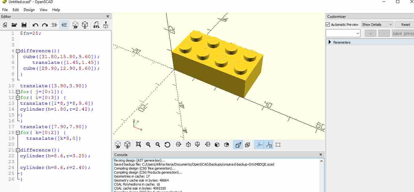
By using cylinder command and the dimension in bracket we get the desired shape.
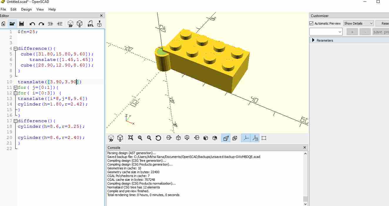
FOR loop is used to copy the cylinder in array.
.
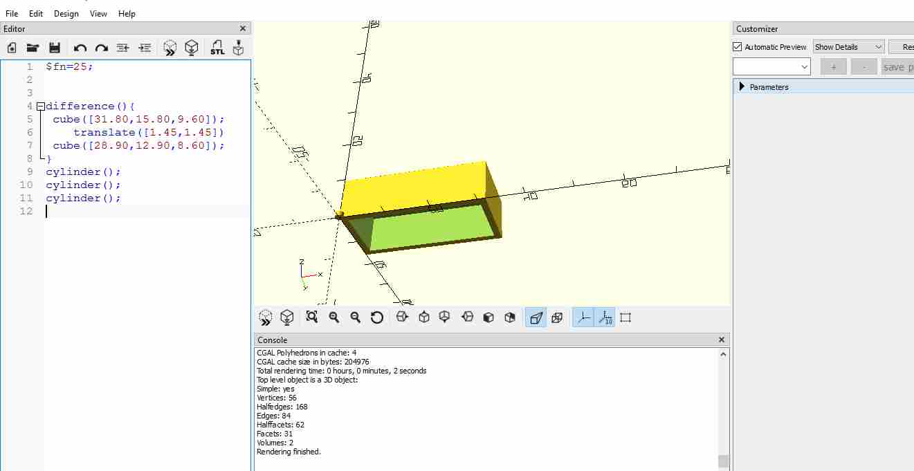
I used normal command name for making cube and cylinder and tranlate to move the part a certain distance and for loop for repeating process.
codes are here:
$fn=25;

difference(){
 cube([31.80,15.80,9.60]);
    translate([1.45,1.45])
 cube([28.90,12.90,8.60]);
}

translate([3.90,3.90])
for( j=[0:1]){
for( i=[0:3]) {
translate([i*8,j*8,9.6])
cylinder(h=1.80,r=2.42);
}
}
translate([7.90,7.90])
for( k=[0:2]) {
  translate([k*8,0])

difference(){
cylinder(h=8.6,r=3.25);

cylinder(h=8.6,r=2.40);
}
}
I exported this file in STL format. Files can be downloaded here:
ONSHAPE
Onshape is a computer-aided design (CAD) software system, delivered over the Internet via a Software as a Service (SAAS) model. It makes extensive use of cloud computing, with compute-intensive processing and rendering performed on Internet-based servers, and users are able to interact with the system via a web browser or the iOS and Android apps.
I made Vase on Onshape.
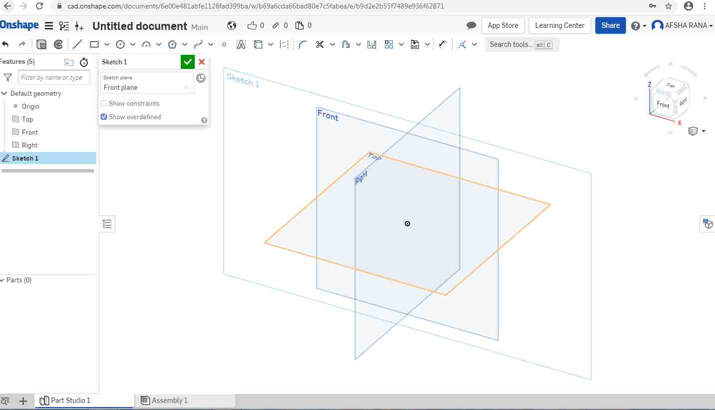
First you have to create a document file by clicking on Document option on top left corner.
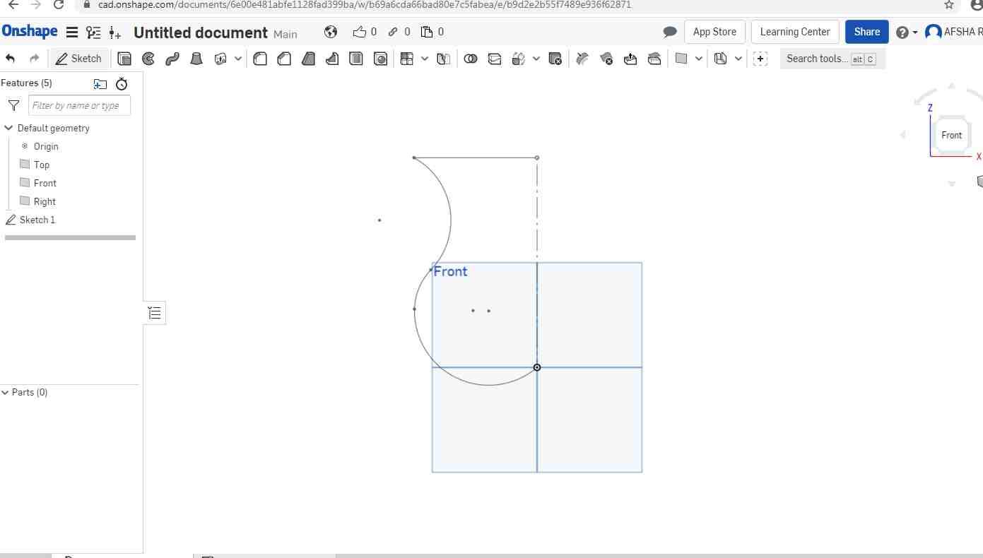
By using Sketch and selecting one of the plane to sketch.With the help of Arc and line I made cross-section.
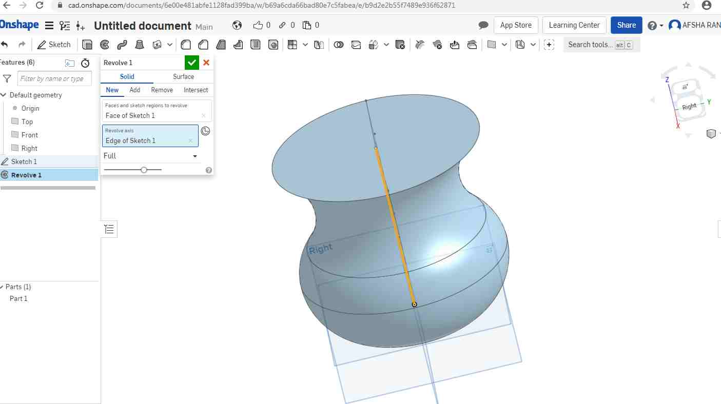
I used Revolve Command to rotate the cross section about line.
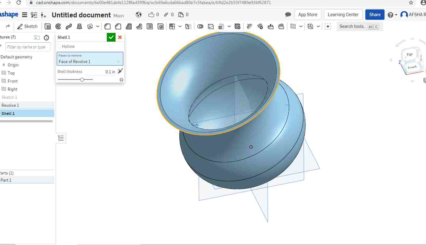
Then I used shell command to make thin wall vase
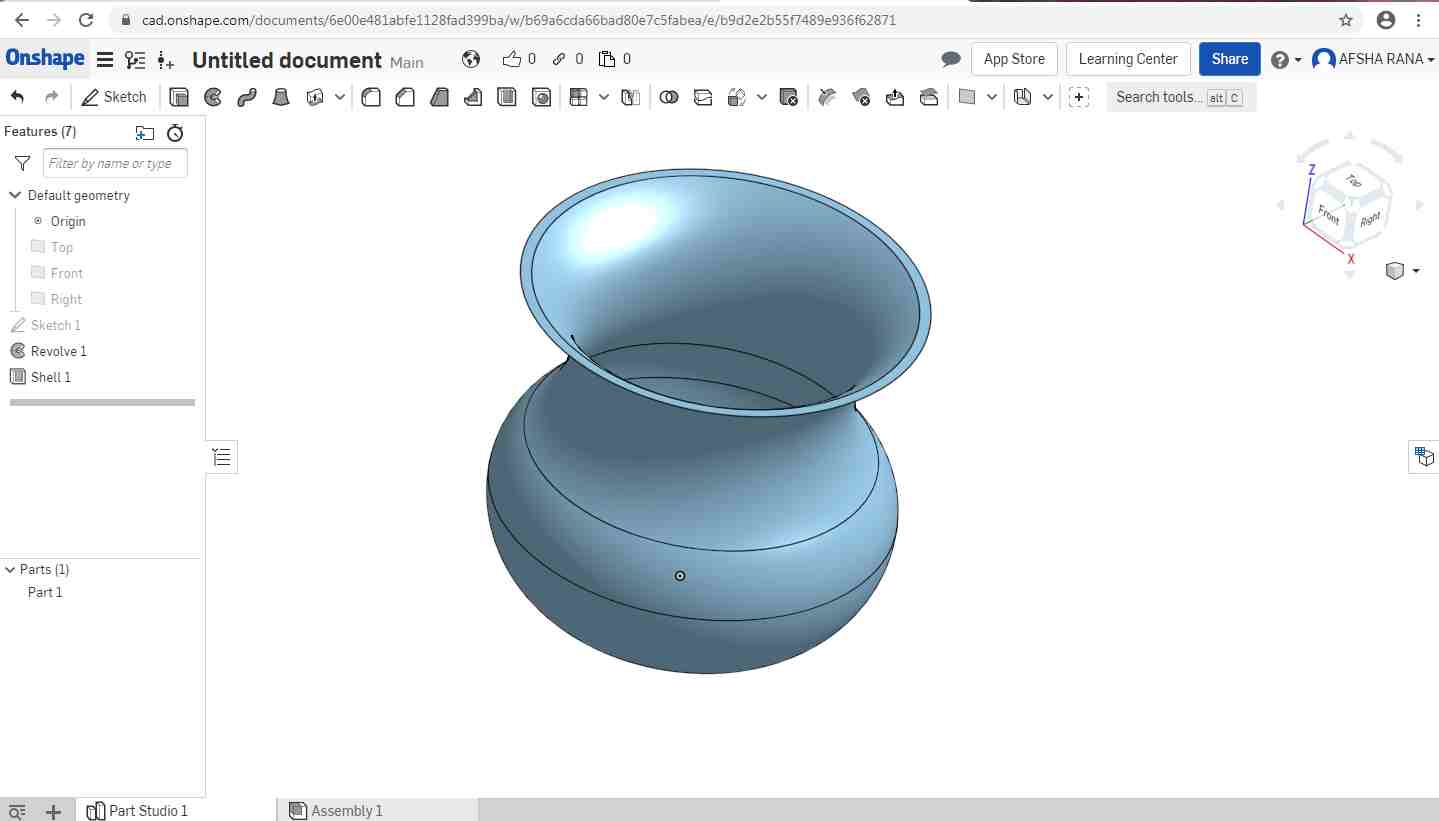
Now the shell is done and Vase is ready.
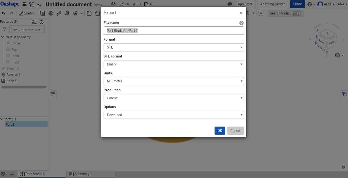
Final Step is to export the file in .STL format.
EXPERIENCE
In 2d software I used Inkscape, very good software to design stickers and other 2d stuff.
In 3D I mostly used Solid Edge which is easy software for simulation and motion analysis.
NX again is paid software but it is parametric software in which you can change directly the sketch in order to change the solid model.
Onshape is open source , cloud based tool and good for new CAD learners. In case of poor connectivity model need to be reloaded again and again.
Openscad on the other hand is CAD tool which I used for first time and it is not that user friendly and its like doing coding and it is not required in other CAD tool.