Electronics Design
In this week the individual assignment is to make Hello echo board of Neil with one led and switch button.And group assignment is to use the test equipment in your lab to observe the operation of a microcontroller circuit board. There are several online and offline softwares available for designing a PCB, mostly all of them have the same workflow.
Software Installaion
Step:1 The installation begins with downloading of sotware from this website
Eagle SoftwareFirst open this link then you have to login and create an account and then it gives you accesss to download it. Run.exe file to install the software.
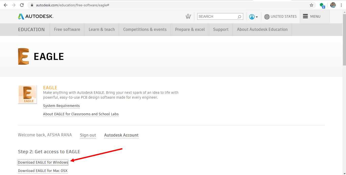
This image shows from where you can install Eagle software
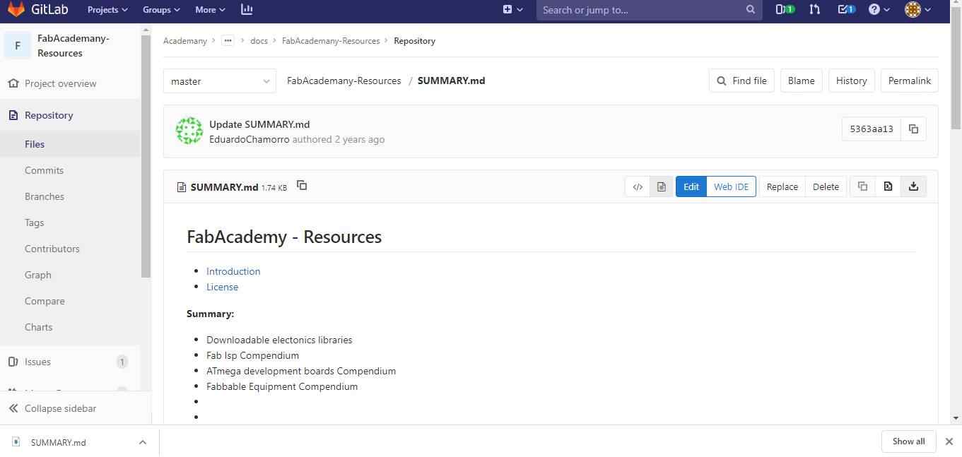
First step is to add fab library to eagle library manager because from that library I got the footprints of component which I will used to design the Hello echo board.
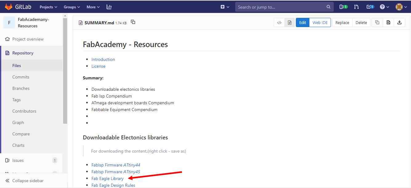
That is available on fabaadameny resources
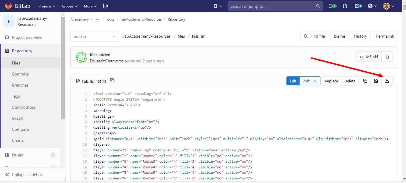
Now download the file on the location from where you can add it.It can be download from here
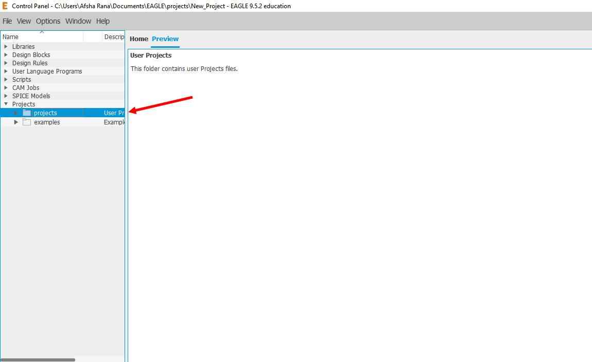
Now open the eagle app.Right click on Project
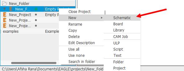
Right click on new project and click on schematic. Schematic is simply a line diagram or connections of all the components that are on your board. In the schematic you can add, select, group, re-arrange etc. the components. Menu on the left side has all these options and are pretty much self explanatory.
And add new project.
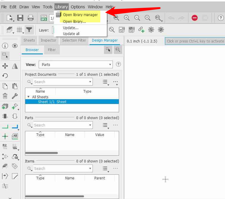
Then click on Library and open library manager
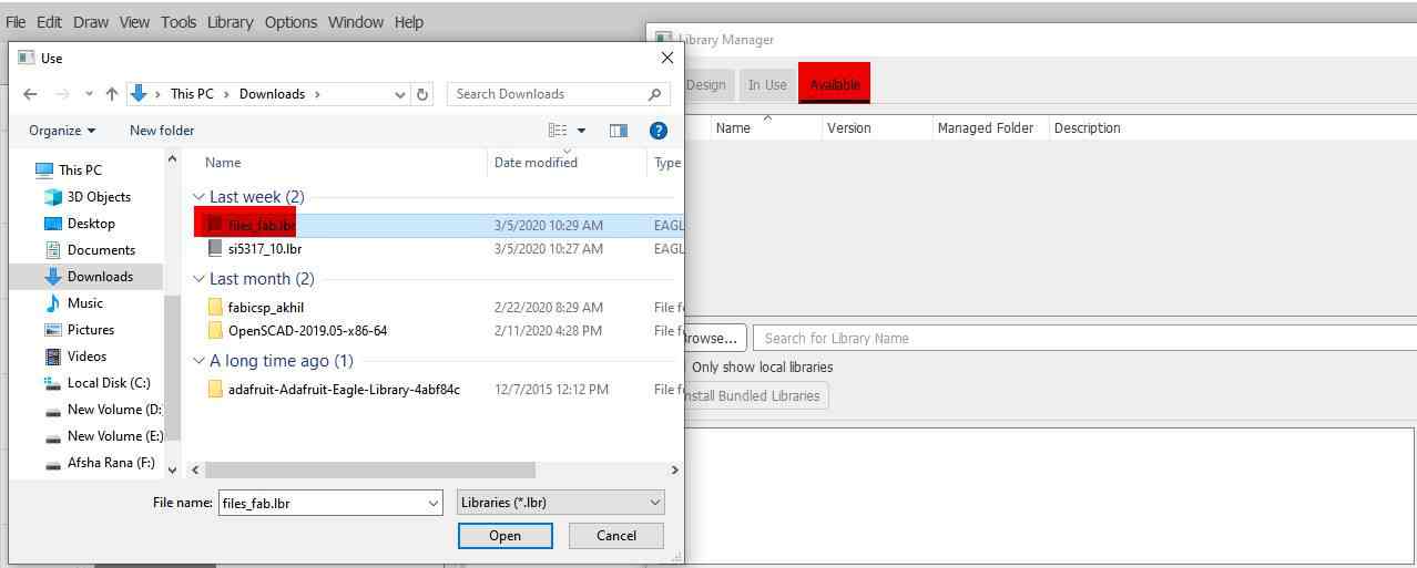
Browse the library and open which was dwonloaded from fab academan resources.and Click on Use.
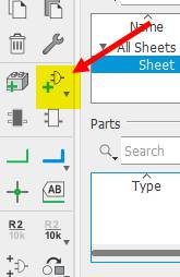
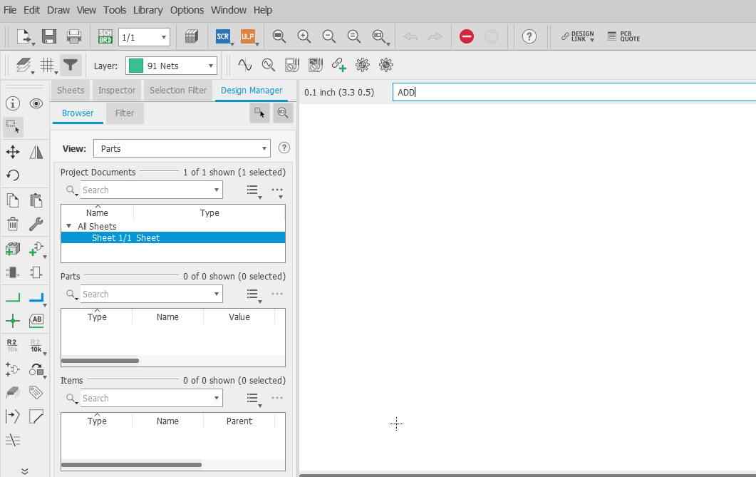
Click on ADD button and add the components which will used in ISP
Before starting further my instructor told us about the basics of electronics component working. I Also google and found this about push button or switch which will be used
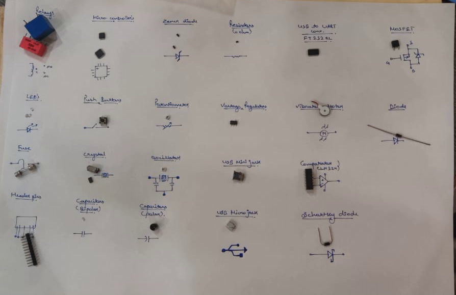
Now I became much aware of the components working.
And after adding component required to design the board.i followed these steps.
1. After adding all the component, select the line tool and draw a small line on the terminals of each component. 2. Add Label to the terminal lines and then Name them. 3. The terminals which have the same name are automatically connected, you’ll be prompted before that. This way of connecting components rather than drawing lines from one terminal to another is easy, less messy and more understandable.
First I tried with ATtiny 44 and schematic of two LED and switch button
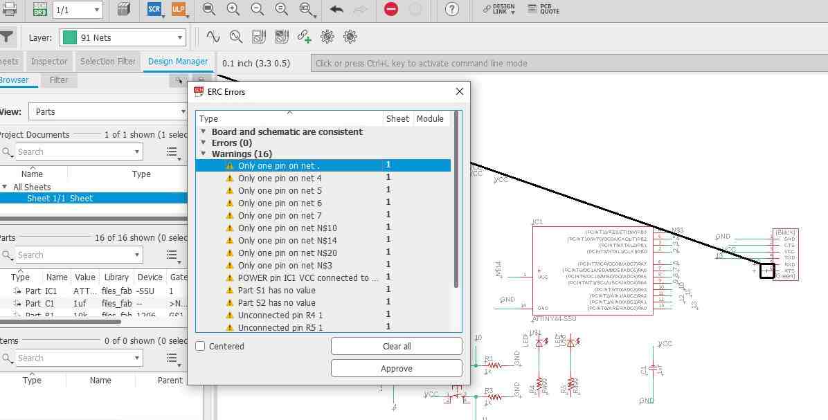
Then error in schematic has been checked by typing ERC on command line.These are the errors which came when i first checked my schematic.
ERC is a handy tool that allows to point out common errors in your schematic. An ERC will check for the following issues:
Source : https://www.autodesk.com/products/eagle/blog/schematic-basics-part-3-erc/
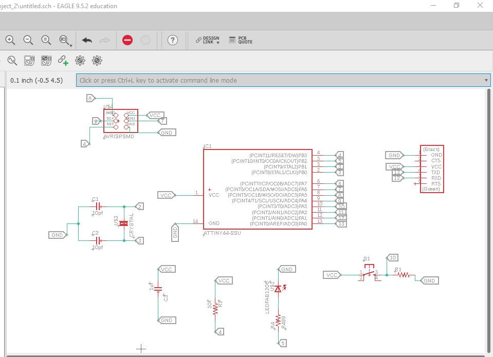
Then I go for one led and one switch.Below is the image showing schematic of board.
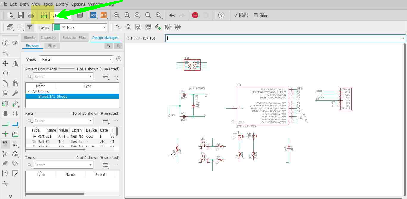
Now come to board:The window open when the SCH-BRD button on top clicked
1. The board is the actual representation of the physical board, all the components in the Board window are according to their footprint, size.2. When you open the barred window, you see all the components on the bottom left. The black space with red outline is your canvas where you have to place your comments.
3. Component is connected with a yellow line which are called air wire. These are there to show the connections between the components.
4. Layer, there are several layers on which you can route the components or add them. For my board the Routing was done on the top layer and the boarder outline was on the bottom layer.
5. Next step is to arrange all the components on the canvas, make sure you hit the Ratnest every time you place or move a component. This will reroute the airwires in a more optimal way.
6. I used Autorouting to route the board, but you can also choose to manual route. Before routing the board, I set the Net Values according to the specification of the tool I’ll be using.
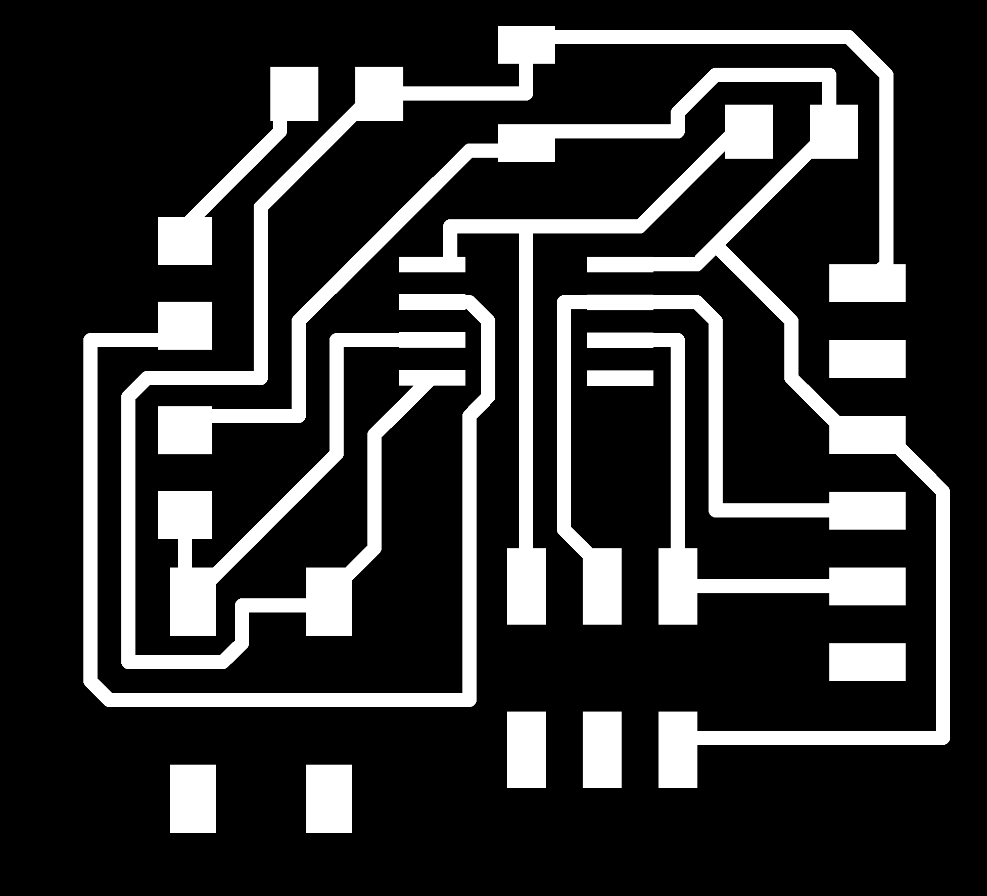
Hello Echo Board with Attiny 45

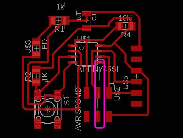
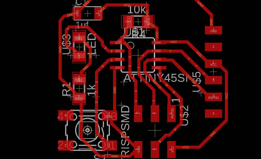
This is the png for hello echo board with ATTiny 45.I took reference from it
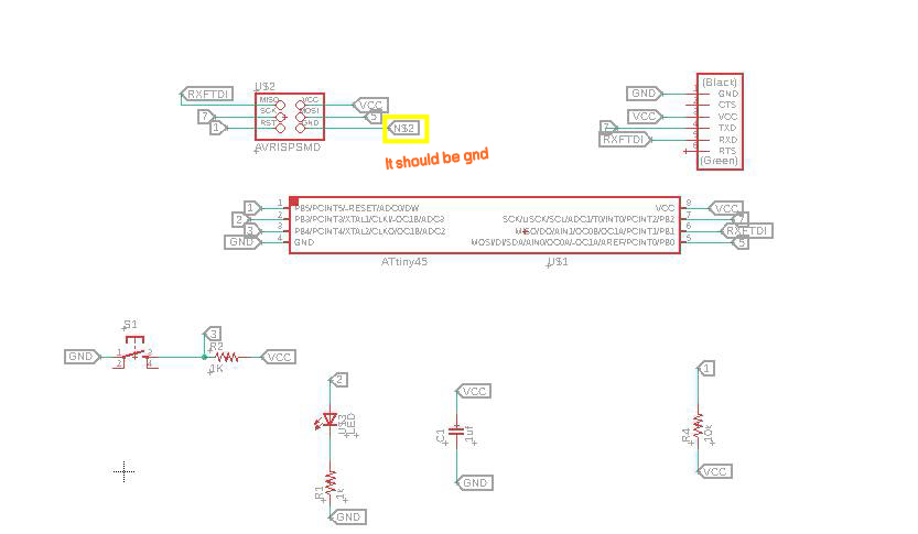
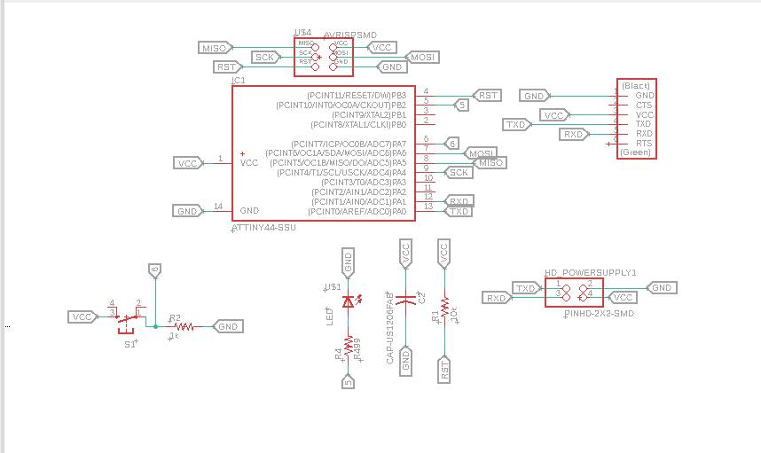
This is the schematic and I put button on pin 3 and LED on pin 2.I did one mistake the avrisp gnd pin I did not give GND to it.It is some random pin.
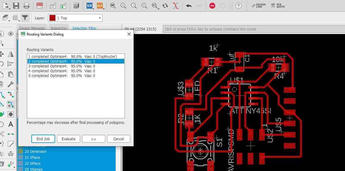
After various iterations, I got 95% routing of board.
I dint check DRC rules and dint notice the airwires which shows the pins which was not connected.
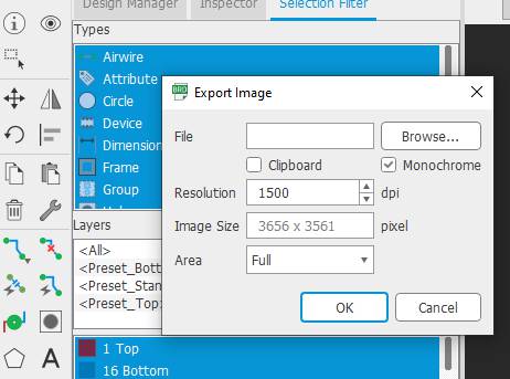
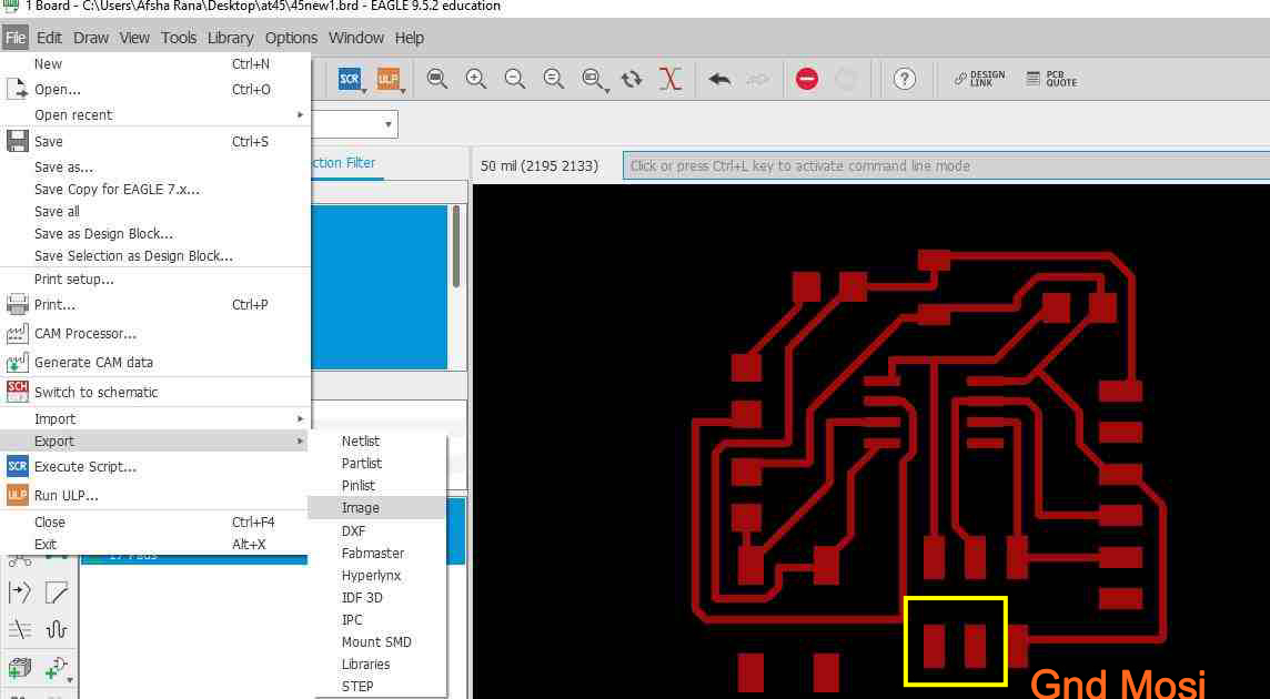
Export the images on these settings.
I exported the image.
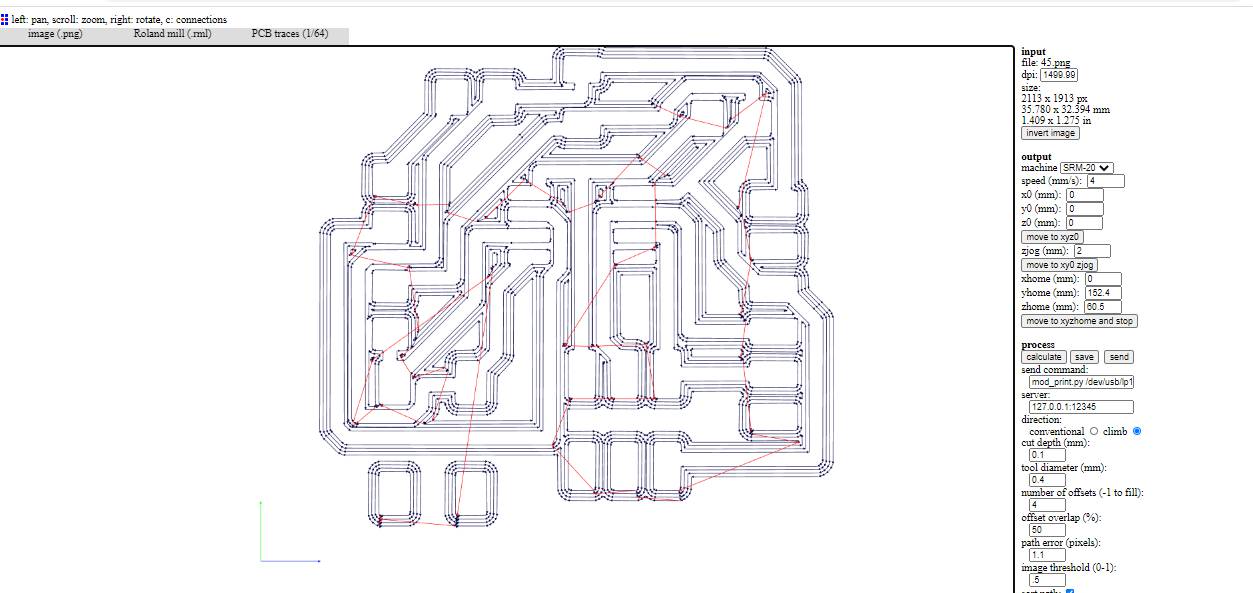
The tool path for rml file is same as process done in Electronics Production week
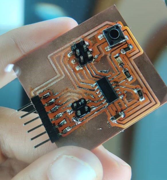
Hello echo board after Milling
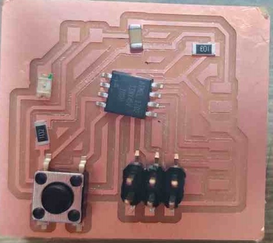
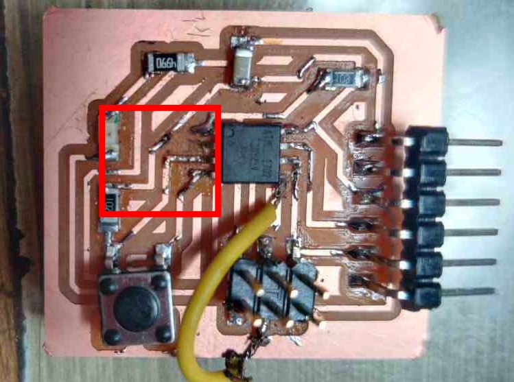
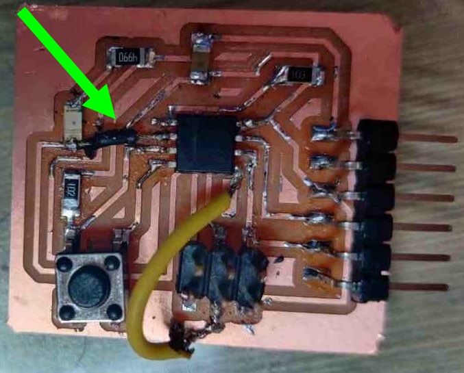
It is the only airwire which was there as gnd pin not connected actually
This pcb I designed for the very first time and at that time I did not know that if we were not able to route automatically the design 100%,you have to manually route the PCB or you can add zero ohm resistor in order to overlap the paths instead of using jumper wire as this attempt was in hurry and soldering was not that good.
I connected two jumpers.I want it to design again as so much things were missing. Due to pandemic I got some time in lockdown to work on it
Meanwhile I designed it again and I also designed one with Attiny 44
After Unlock one and lap opened I decided to go with Attiny 44 as I already tried an attempt with Attiny 45.
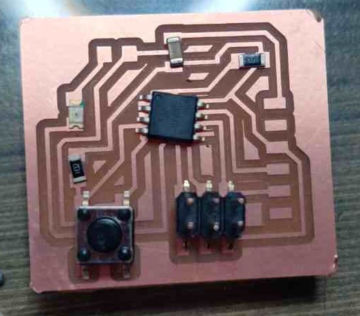
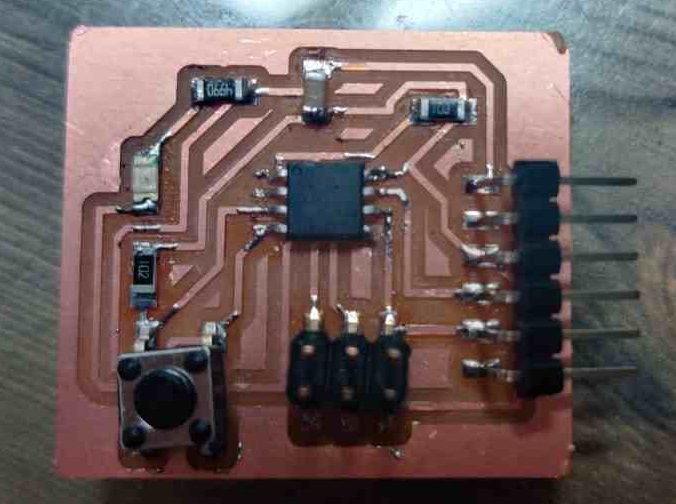
Hello Echo Board with Attiny 44
This is the new schematic file in which I added LED and button.
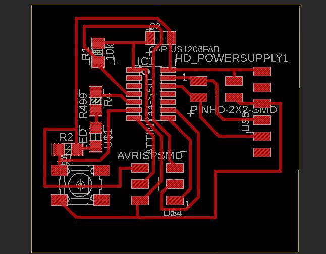
This is the final pcb for Hello Echo Board.
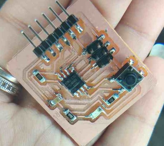
LED WITH BUTTON
In this I have connected vcc and gnd of my board to arduino to give power to my board and programmed it with AVRISP mkII.The process for burning bootloader I explained in Embedded Programming week
Arduino Code
This is the code which I used from examples of Arduino IDE
    // constants won't change. They're used here to set pin numbers:
    const int buttonPin = 7;     // the number of the pushbutton pin
    const int ledPin =  8;      // the number of the LED pin

    // variables will change:
    int buttonState = 0;         // variable for reading the pushbutton status

    void setup() {
      // initialize the LED pin as an output:
      pinMode(ledPin, OUTPUT);
      // initialize the pushbutton pin as an input:
      pinMode(buttonPin, INPUT);
    }

    void loop() {
      // read the state of the pushbutton value:
      buttonState = digitalRead(buttonPin);

      // check if the pushbutton is pressed. If it is, the buttonState is HIGH:
      if (buttonState == HIGH) {
        // turn LED on:
        digitalWrite(ledPin, HIGH);
      } else {
        // turn LED off:
        digitalWrite(ledPin, LOW);
      }
    }
GROUP ASSIGNMENT :
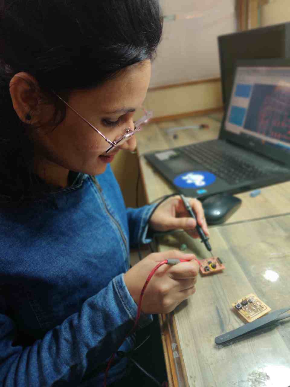
This week assignment was to use the test equipment in your lab to observe the operation of a microcontroller circuit board
Multimeter
A Multimeter is basically a Paramter measuring tool, which can measure a wide range of parameters, Principally : Voltage (AC/DC), Resistance, Capacitance, Conductivity etc. Its the most common diagnostic tool technicians have, through multimeter debugging comes handy.
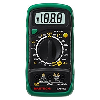
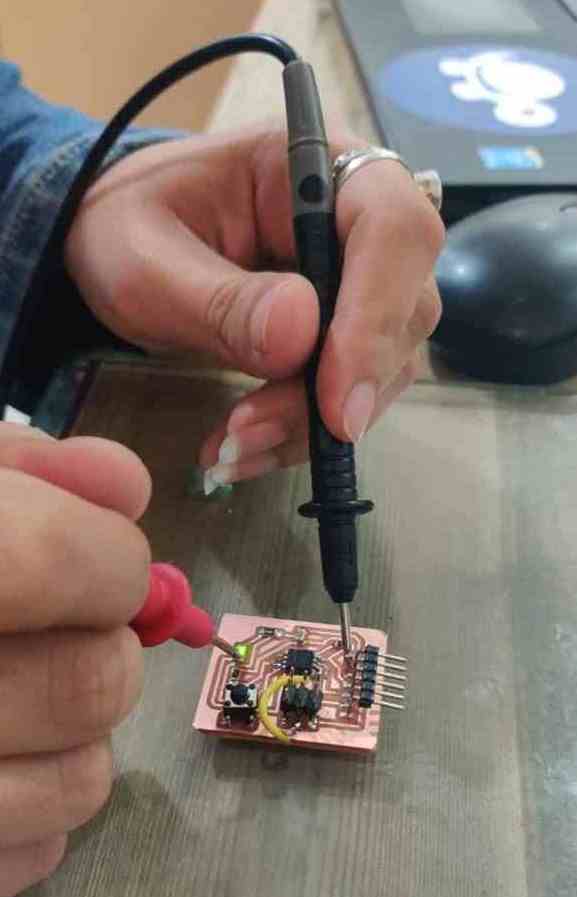
I used multimeter to check the continuity of board
Power Supply
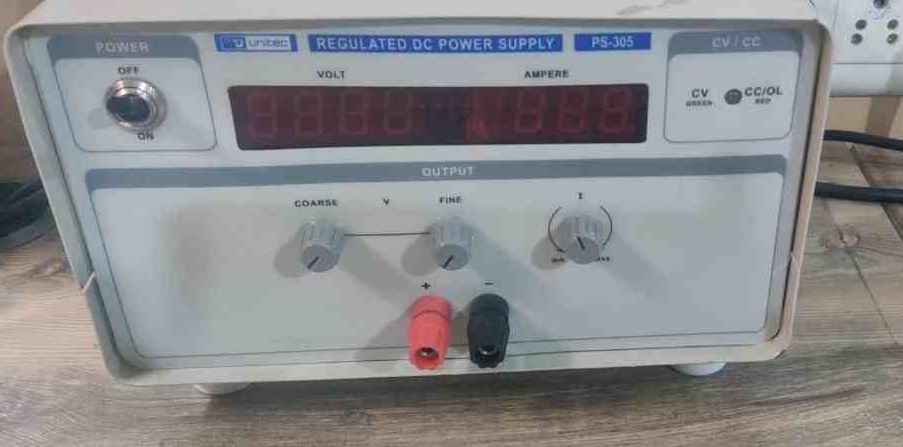
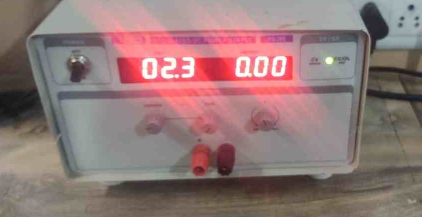
In our lab we have Scientific Unitec PS-305 (0-30V 5Amps) Power Supply .We used to give 5 volt-12 Volt power supply to our boards.
Features:
DC OUTPUT : 0-30Volt
DC CURRENT : 0-5Amp
AC INPUT : 185 - 240 Volt AC
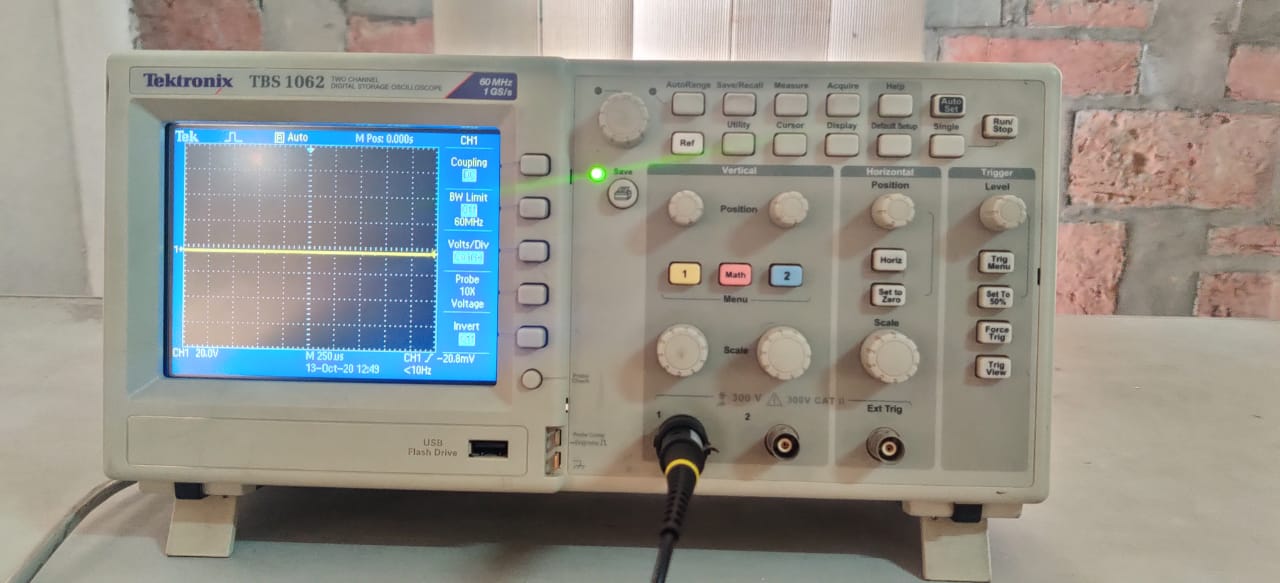
Digital Oscilloscope
About Oscilloscopes
One needs to understand the circuits on signal level, which multimeters fails to do. In this case Oscilloscopes is the answer. A digital oscilloscope measures the signal, and then converts that measurement into a digital format using an ADC converter, after which the data measured is depicted as a digital waveform representation. From this representation various paramters can be evaluated. In our lab we got Scientific TEKTRONIX TBS 1062 Oscilloscopes.
Measuring Digital Signal:
We uploaded Blink code on the UNO board and we observed the pulse signal.Above are the results for the same.
Measuring Analog Signal:
We measured the analog signal by connecting both the probe of oscilloscope to Gnd and Vcc pin of dc motor and rotated the shaft manually

