3D Scanning and Prinitng
In this week,I have performed following assignment.
>Testing the design rules of the 3D printer as a group project.>3D Print an object that cannot be made subtractively.
>3D Scan an object (and optionally print it).
3D Printing
3D printing is also known as Additive Manufacturing where successive layers of a material are deposited on top of one another to create a 3D model with the help of G-codes Which are obtained by slicing of STL file of any Object 3D Model through Slicing Software.
3D Printers in Lab
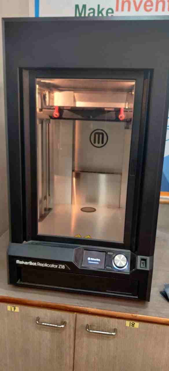
1. MAKERBOT REPLICATROR Z18
To ensure easy, accessible 3D printing, the MakerBot Replicator+ comes with the Smart Extruder+ and all the standard features of its predecessor. The material is non toxic and easy to print with minimal warping. The specification of Makerbot Replicator Z18 are as follows:Print Technology:Fused Deposition Modeling.
Build Volume :{30.0 L X 30.5 W X 45.7 H CM}{11.8 L X 12.0 W X 18.0 H IN}{2.549 cubic inches}.
Filament Diameter : 1.75 mm
Filament Compatibility : Makerbot PLA Filament [Large Spool]
Nozzle Dia: 0.4 mm
Software which is used for slicing is MakerBot Print Software
2. Ultimaker 2.0
Print technology: Fused Filament FabricationBuild volume :223 mm / 223 mm / 205 mm
Layer resolution Fast: 200 micron (0.2 mm)
Normal: 100 micron (0.1 mm)
High: 60 micron (0.06 mm)
Ulti: 40 micron (0.04 mm)
Positioning precision 12.5 micron / 12.5 micron / 5 micron
Filament diameter : 2.85 mm
Nozzle diameter : 0.4 mm
Print speed : 30 mm/s - 300 mm/s
Travel speed : 30 mm/s - 350 mm/s
Software which is used for slicing is Cura Software
GROUP ASSIGNMENT
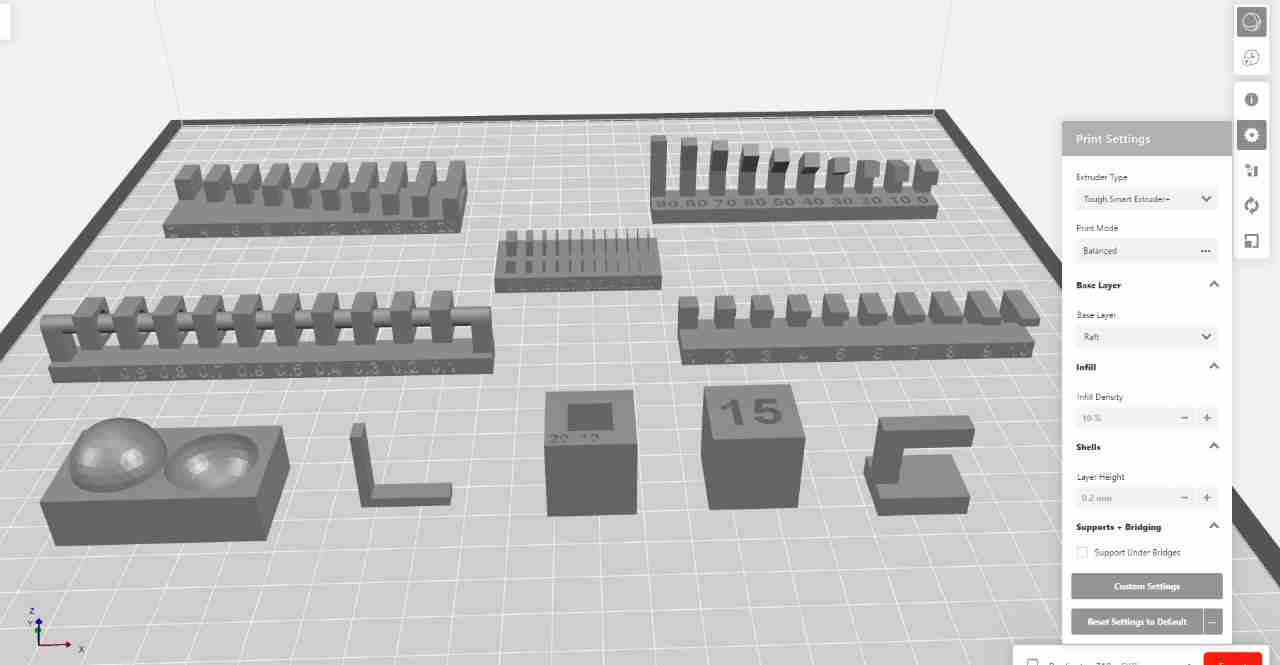
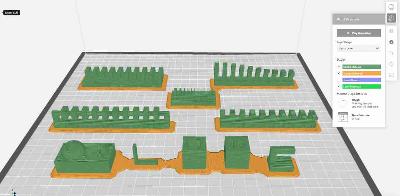
In group assignment we decide to print the STL files from Fabacademy.For this we used Makerbot Replicator Z-18 3D Printer.
The settings are:
1. All the parts are printed without any support.
2.Infill:10%
3.Layer Height:0.2mm
4.Raft :On
5.Material Used:Tough PLA(Slate Grey)
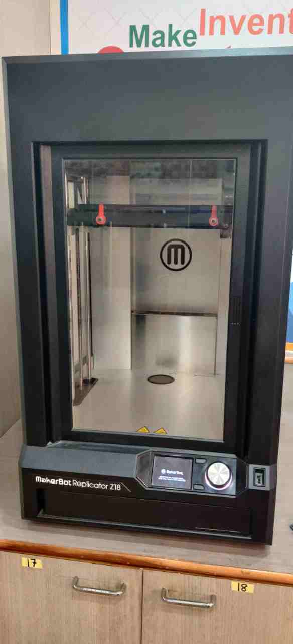
This is the 3D Printer which we used for group assignment.First we have to give power supply to it.
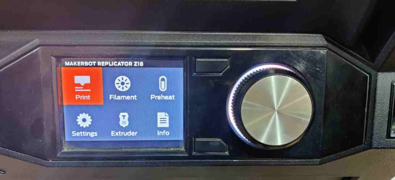
After Power ON the printer, there is a wheel which we have to rotate to go through different option.
There is command showing directly to give print to it by pressing the wheel.
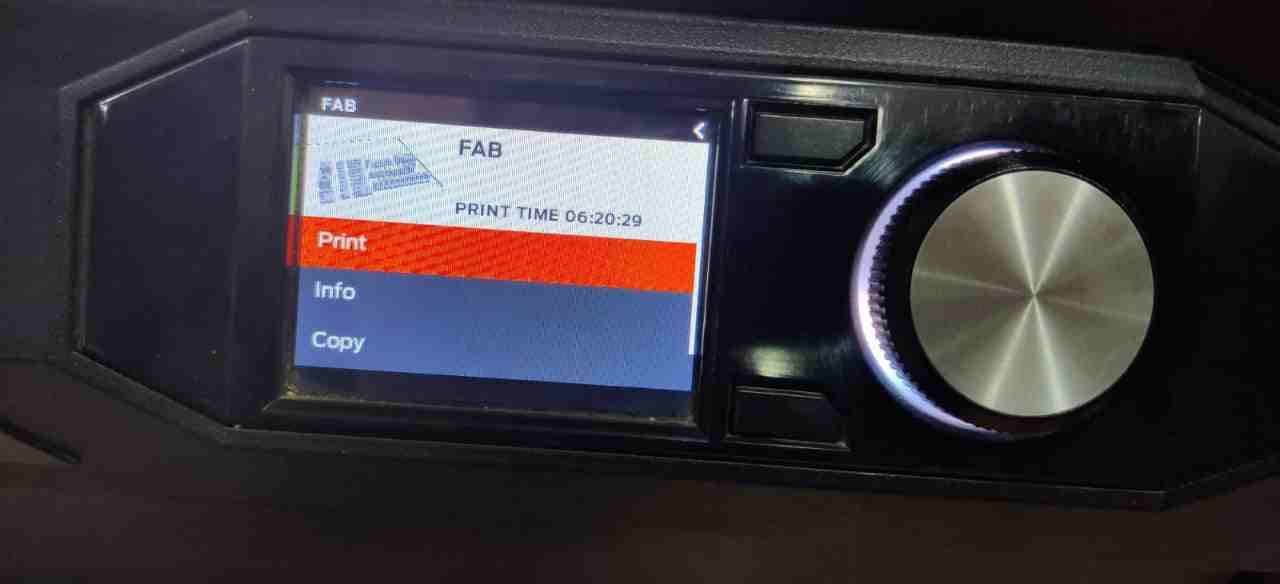
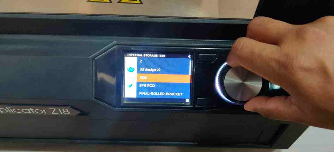
When we press print there is option to give print through USB or internal Storage.
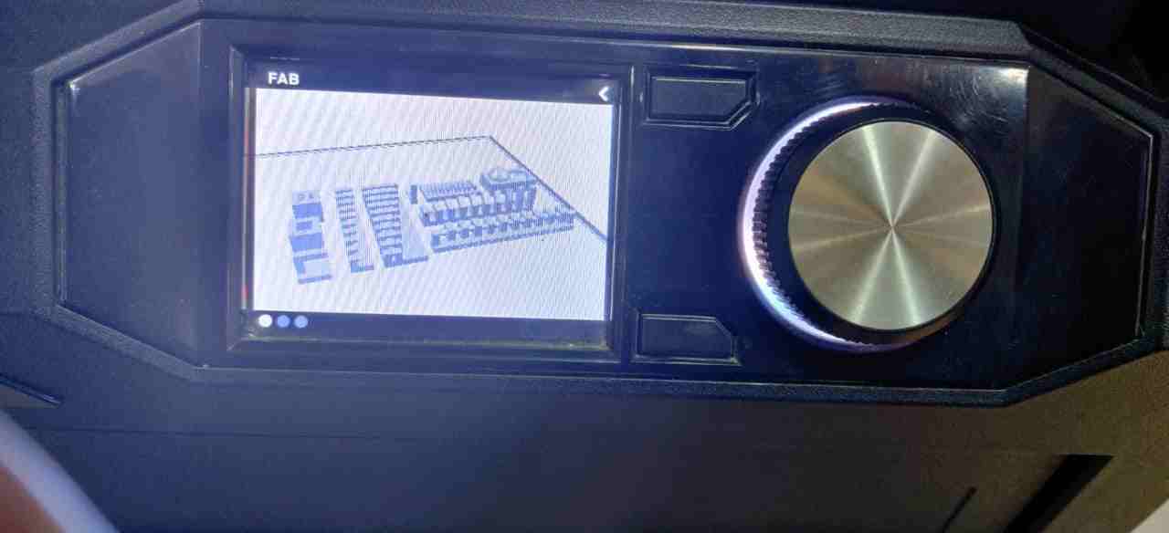
We choose USB as we save the makerbot print format file to give print.
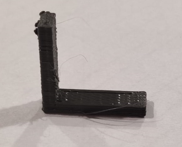
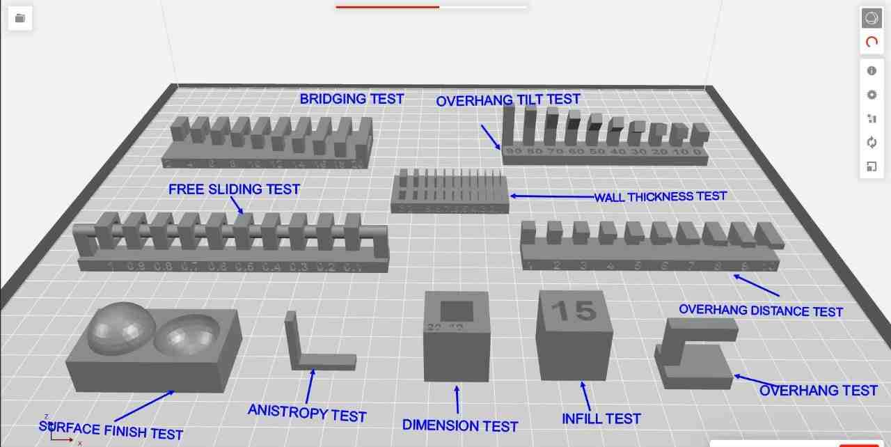
This is the L section which comes fine
This is the L section with different orientation.In this the material chipped off as there was no support for overhang section.
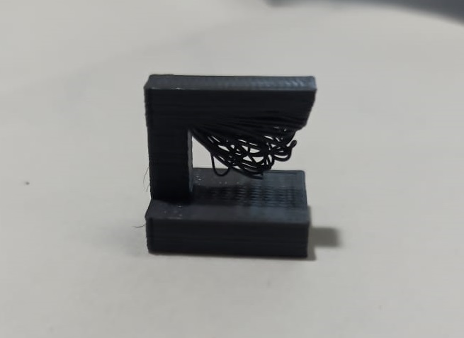
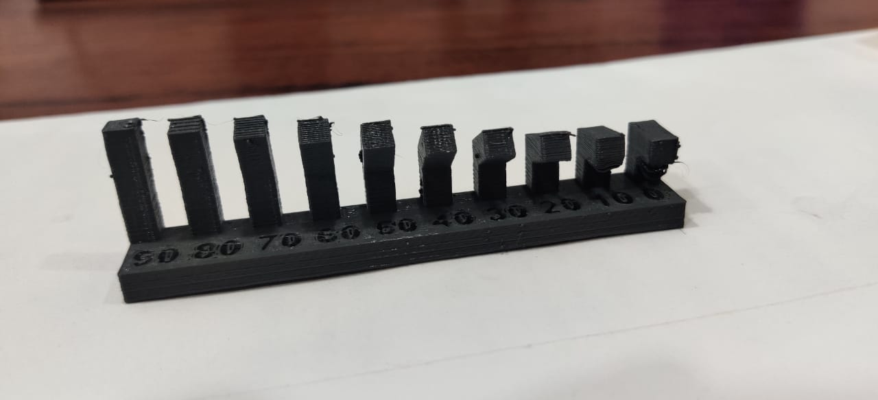
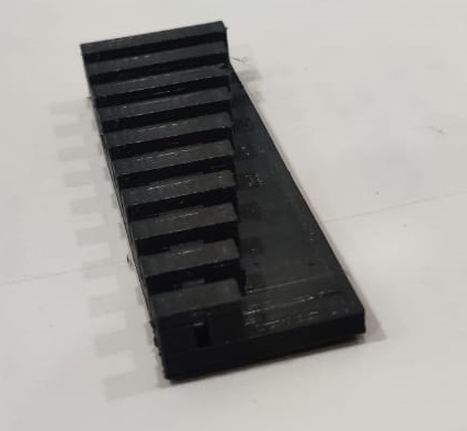
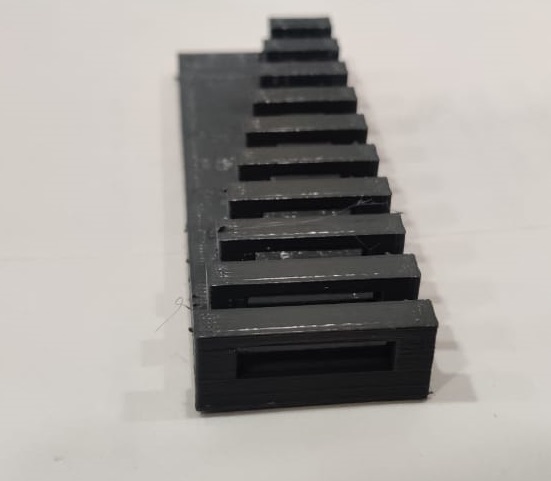
This block shows box showing infill test.
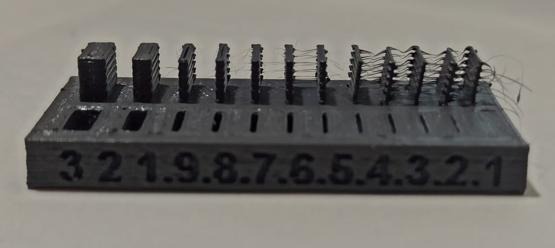
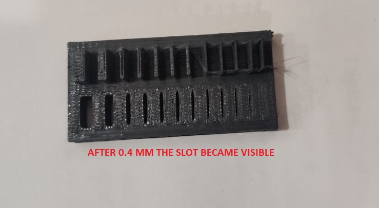
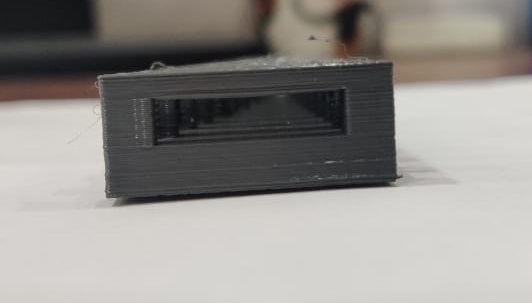
In this test we are able to find that for particular wall thickness,the slots are of particular dimensions or not. The slots are visible after 0.4 mm thcikness.
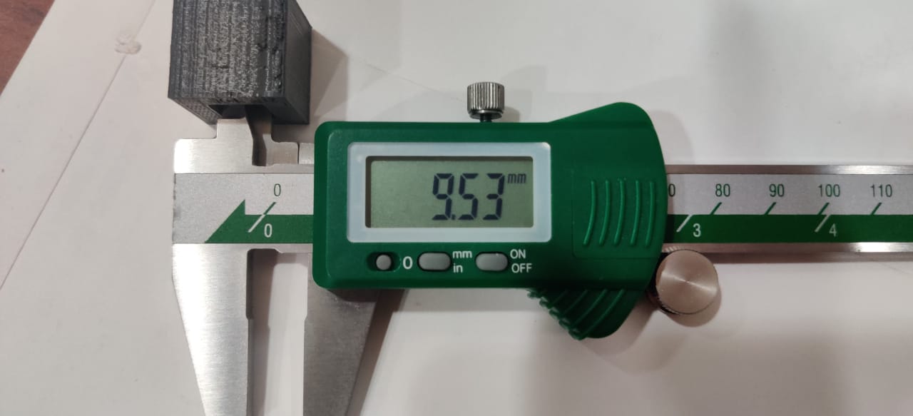
The block had internal cavity of 10mm which after printing comes out to be 9.53mm which is 0.47mm less than the actual size.
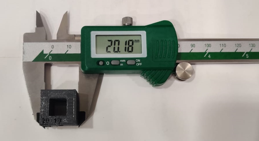
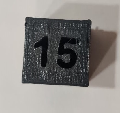
This is the cube which was printed on Makebot.For this I found the size of cube icreases by 0.18mm.
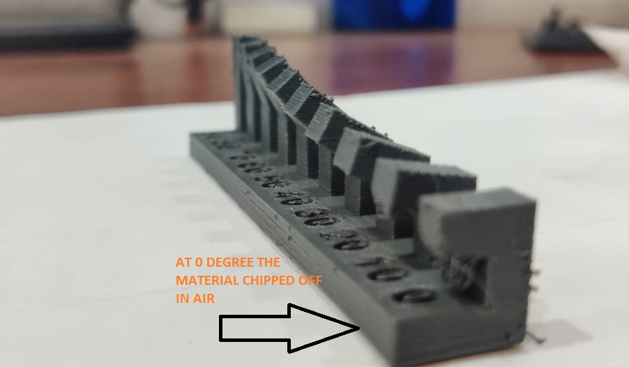
At straight L section at 90 degree was printed good and at angle of Zero degree, it started hanging.
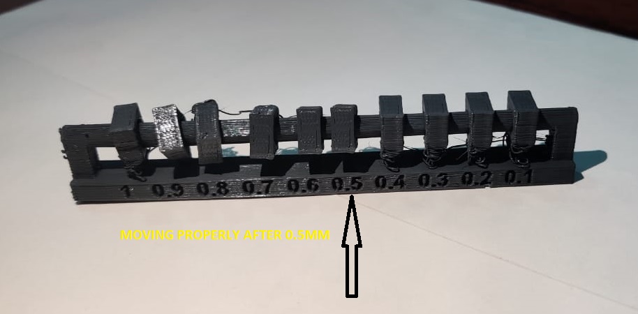
This image is showing that the hole clearance at which block started moving on shaft is 0.5mm before that upto 0.4 mm it is fix.
Upto 10 mm of overhang of section, the material chipped off from surface
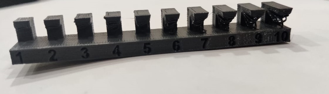
It is showing Bridging test which comes out to be perfectly fine. Bridging is when printer prints a flat,horizontal part of the model mid air.
All files are given on Neils page. Files Can be downloaded from
INDIVIDUAL ASSIGNMENT
In individual assignment I dicided to make Earing.So,I made 3D Printed nested earing on Makerbot.
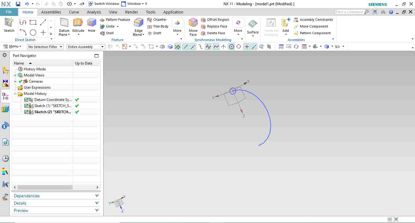
First i made sketch of one the ring for nested earing ,i draw Eclipse of 15 mm major dia and 10mm minor dia and guide is semicircle.
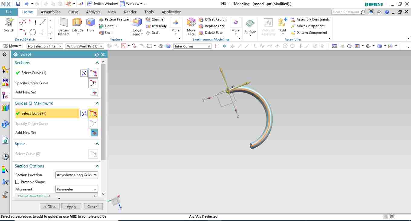
In which i used swept command
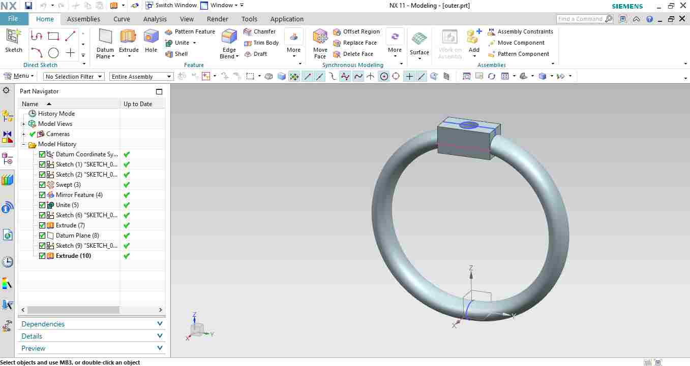
Then i used mirror feature to mirror it and made a cuboidal block at one of its end.
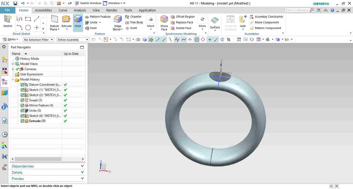
Then the other ring of smaller size is made with one hole.
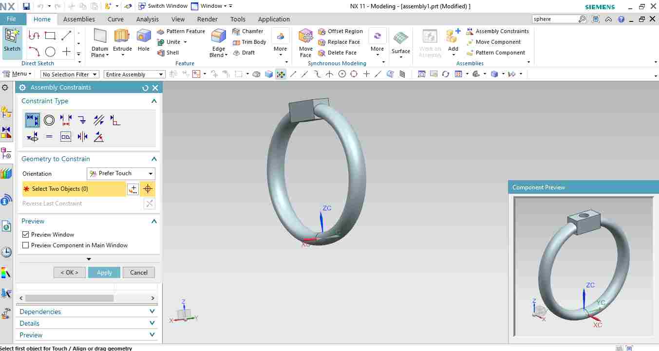
After I used assembly to assemble all the components.
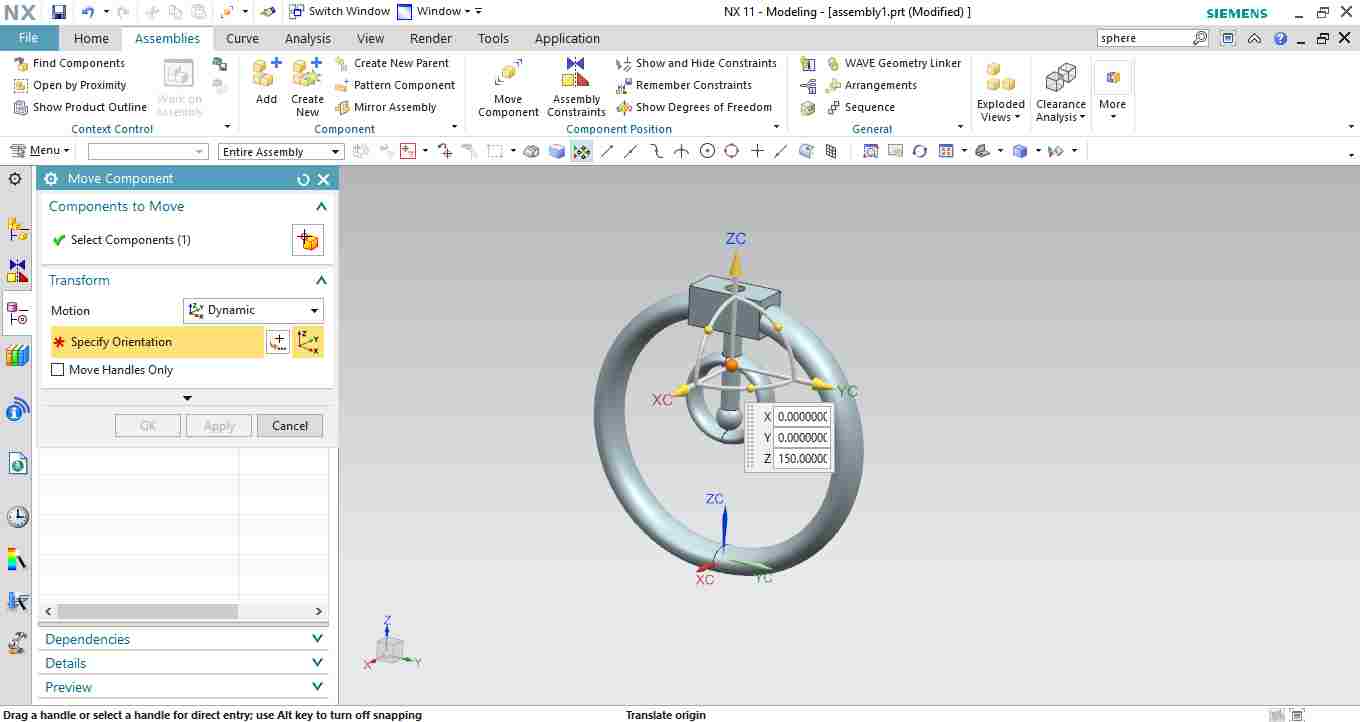
In assembly, by using add component,i added one by one component.
Through align constraint i ailgned all the axis of the cylidrical holes and Move command is used to move one part to translate in three direction and rotate it in three axis.
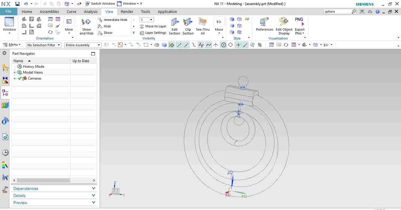
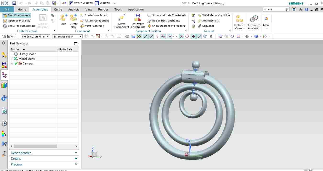
This is the wireframe model.
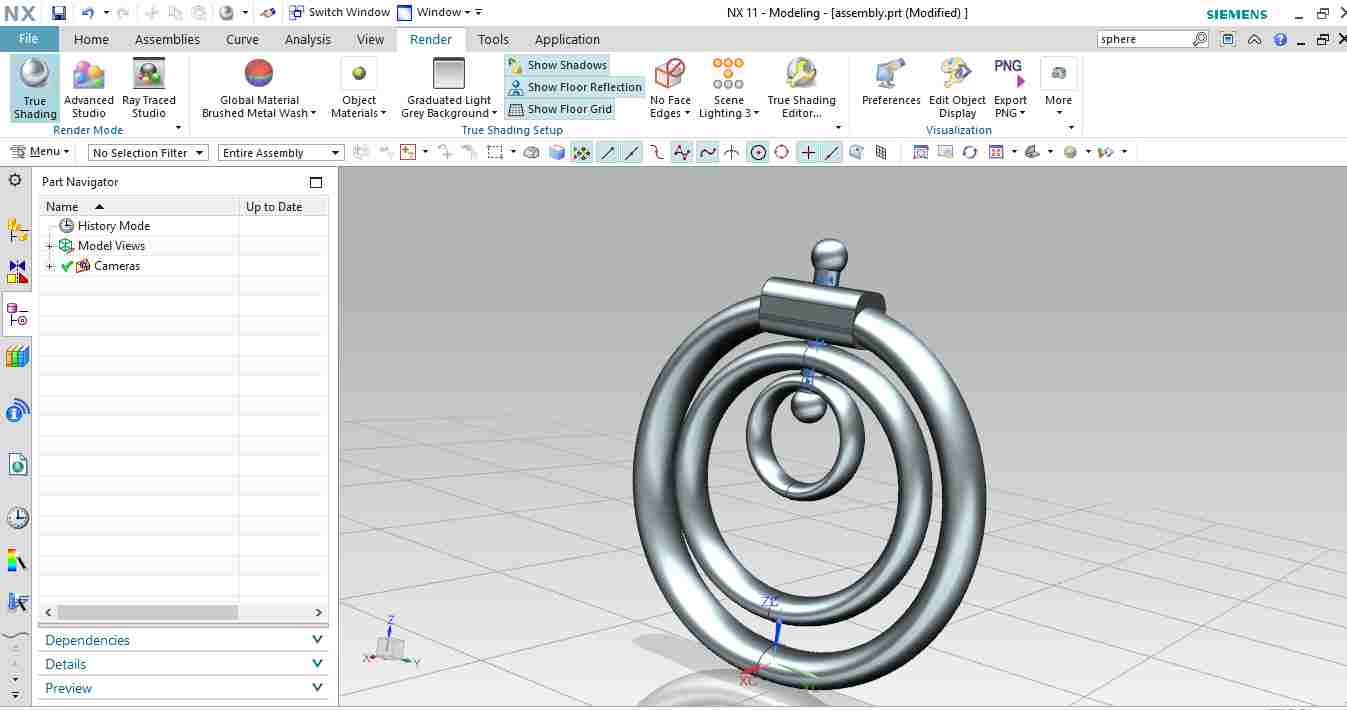
This is the assembly with some rendereing.
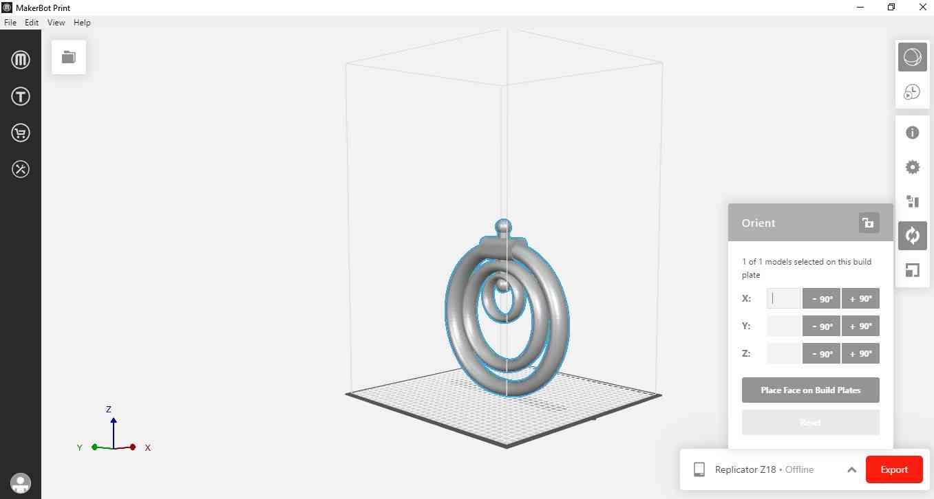
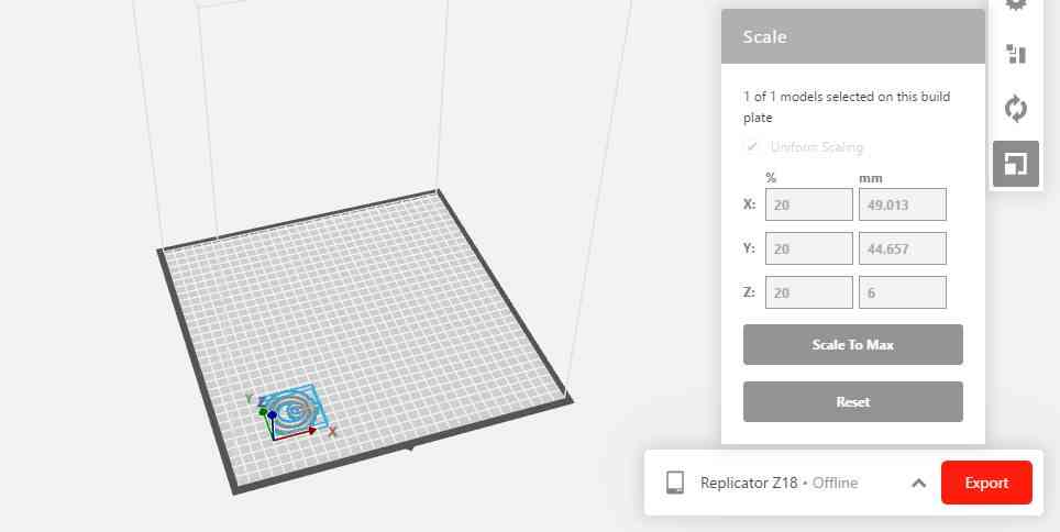
In makebot print First I imported file as STL assembly file. After that i do rescaling to 20% and Orientation is important for optimizing the print.
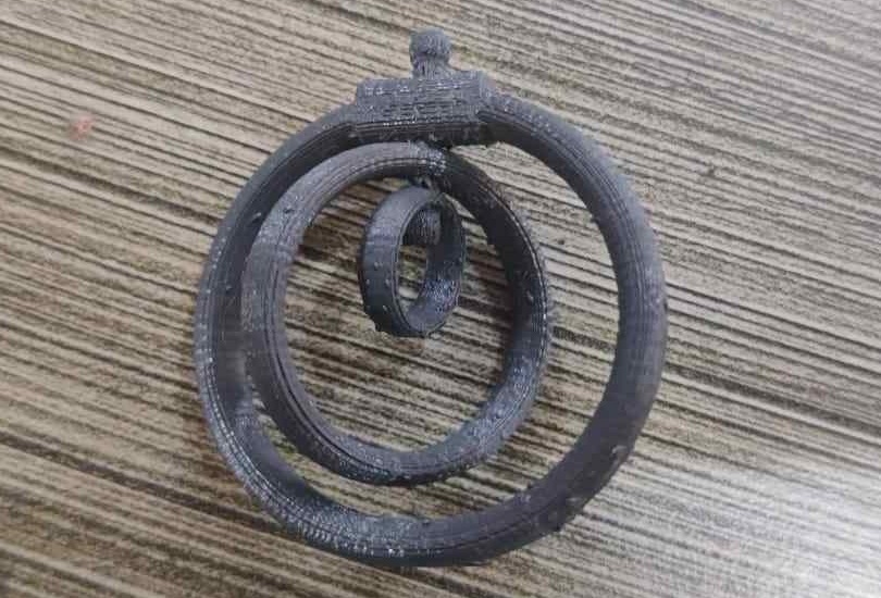
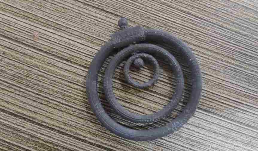
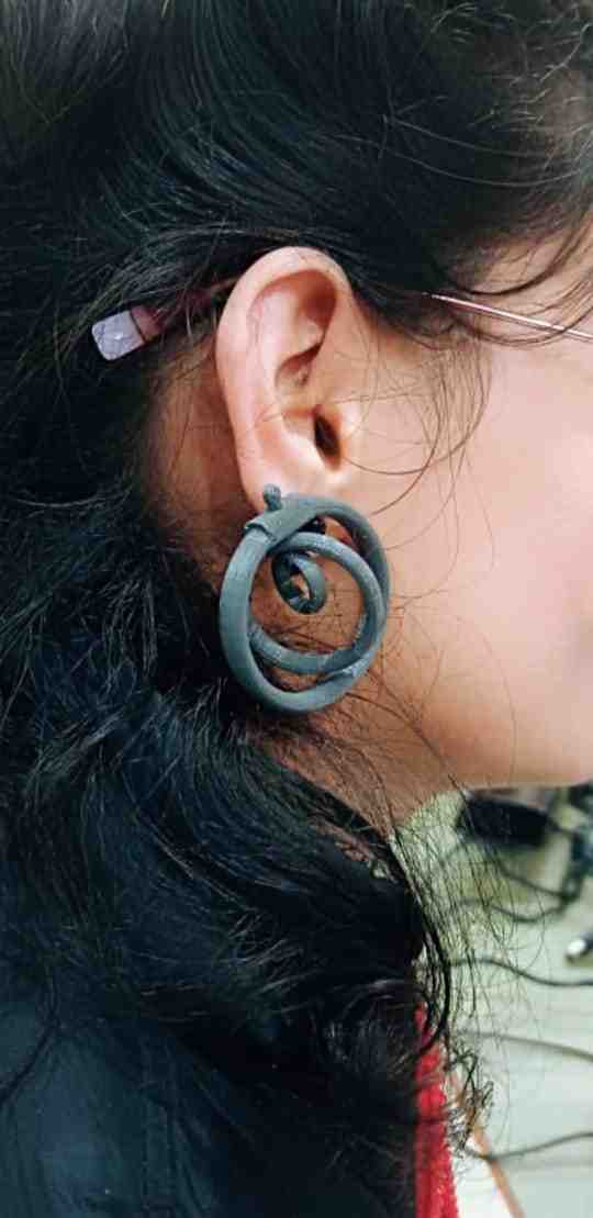
These images are showing the 3d printed part of assembly.
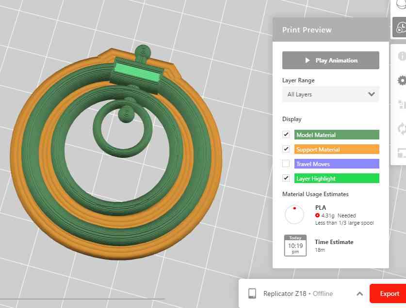
Setting for this print
1. Layer Height : 0.2 mm
2. Raft type : Brim
3. Infill : 10%
4. Material Used : Tough PLA
5. Printing Time : 18 min
6. Support : off
Failure
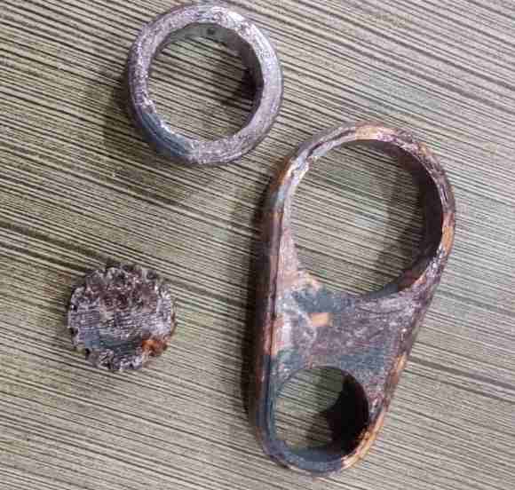
After my first print on Earing,I saw that for raft setting,it sticks on the raft and did not remove Properly
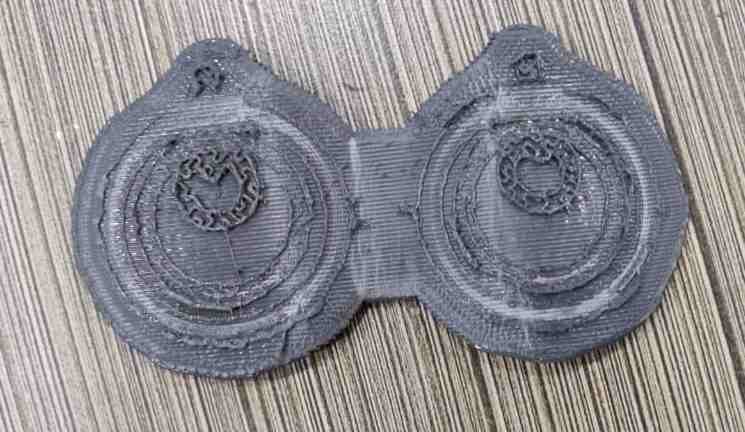
These images showing the raft and the failed part.
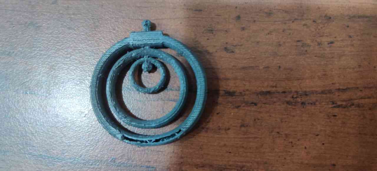
Conclusion
I chnaged the raft setting and selected brim option so that it can remove easily.After doing this I found my print perfect.Earing Assembly by afsharana1993 on Sketchfab
Fidget Bearing
Second thing i tried was fidget bearing, which i designed on Solid Edge and printed on Makerbot.
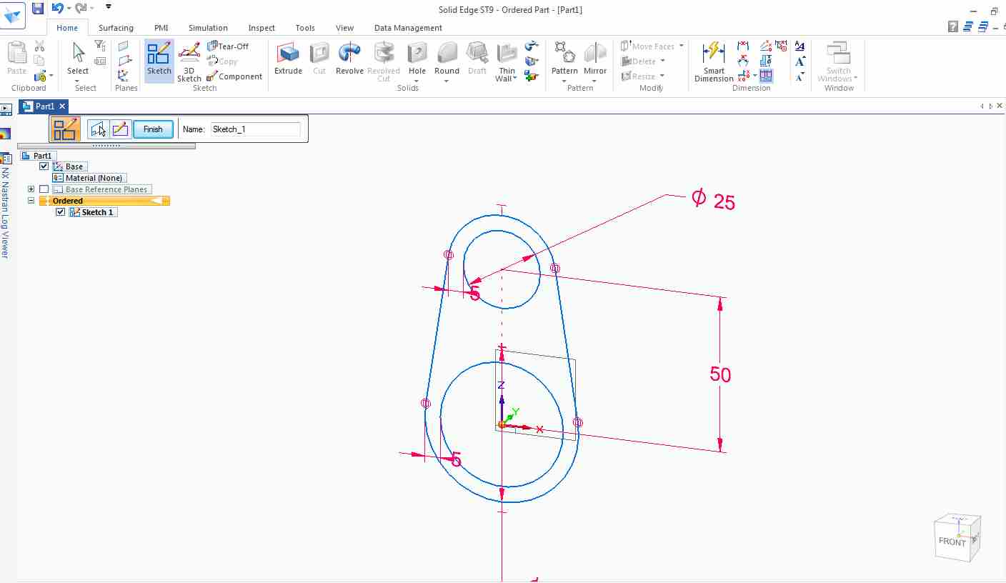
I started with sketch command in ordered mode
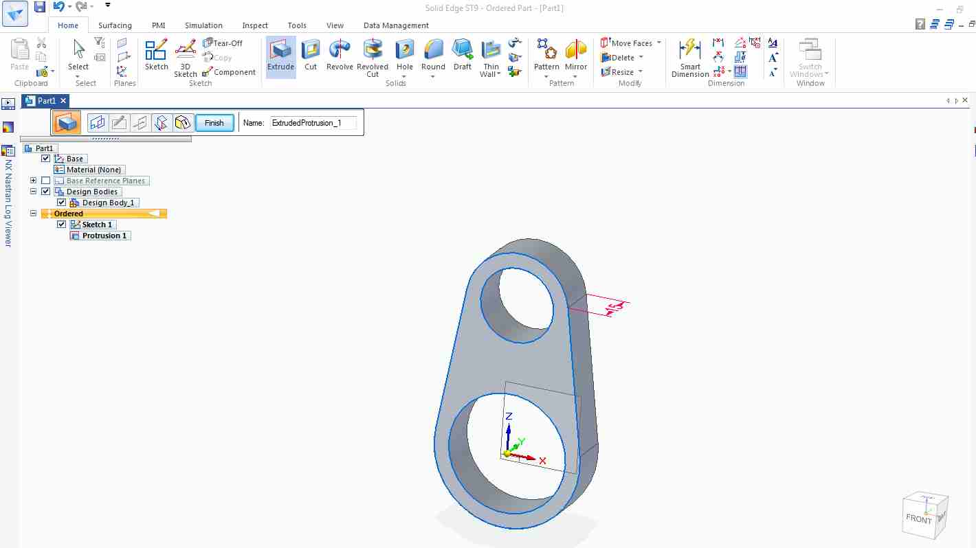
By Extrude command,the sketch is converted into 3d part.
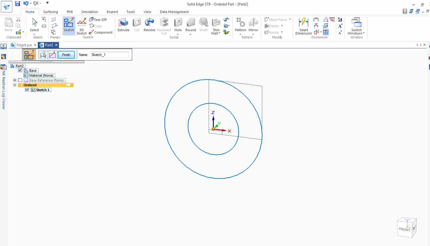
For cylinder I made two circle.
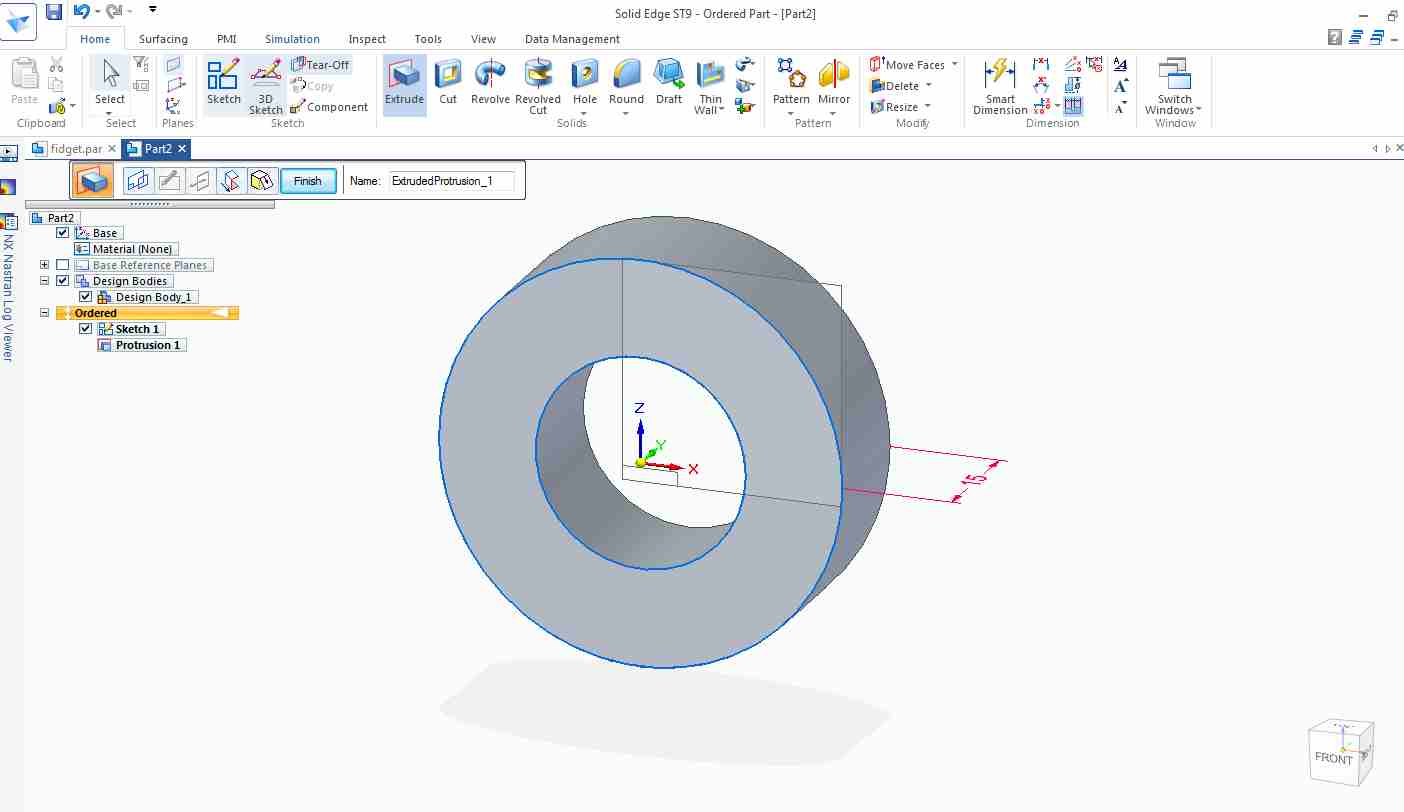
Then i extruded it.
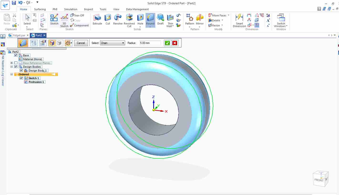
Round command has been used to round the edges.
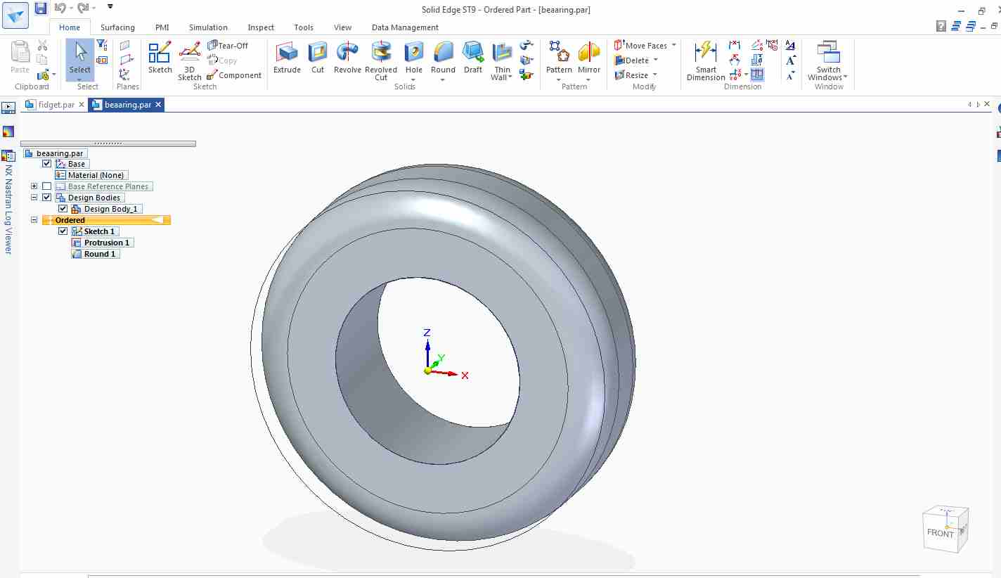
This is the bearing.
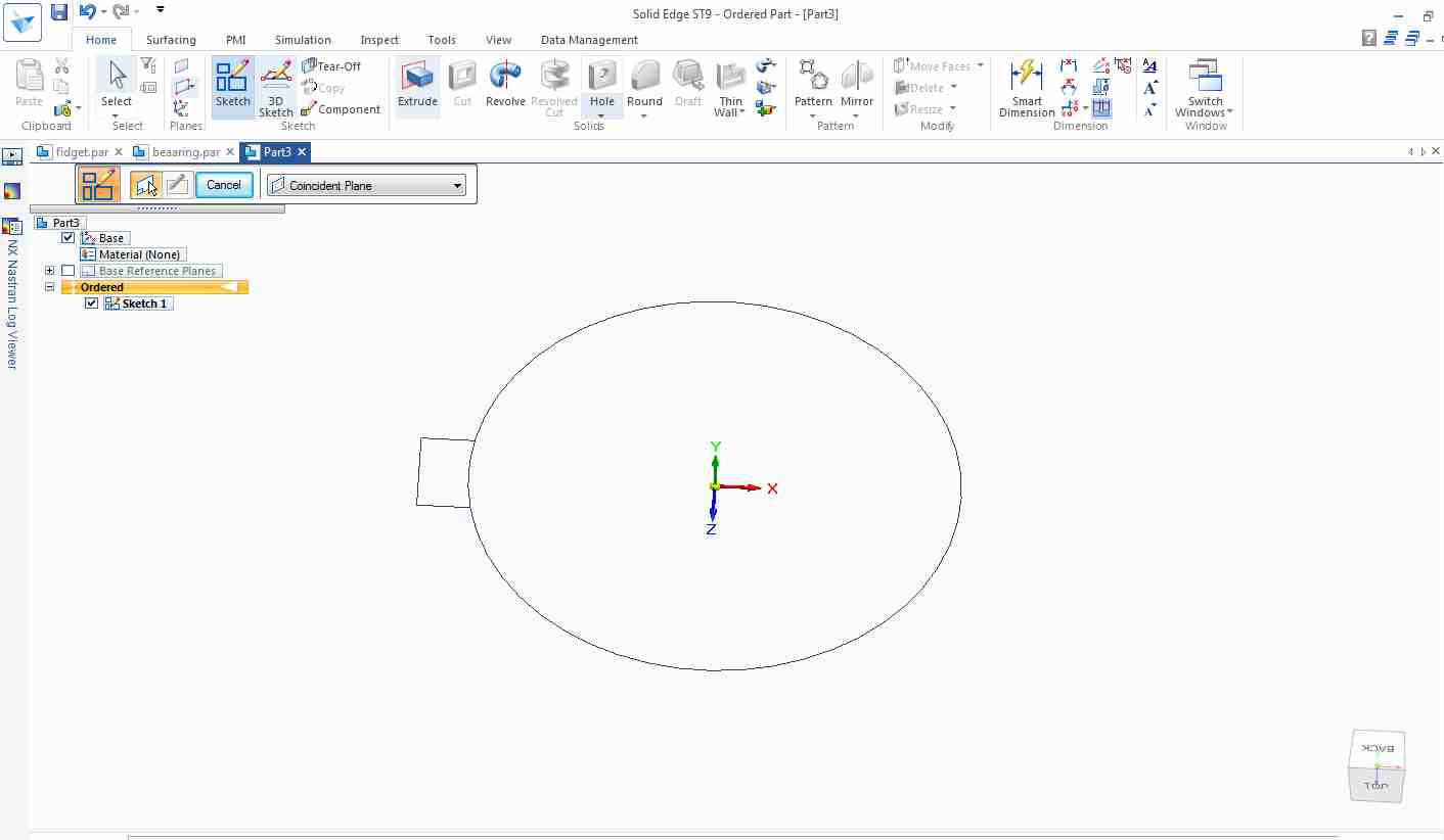
For gear,i made a circle and made a rectangle.
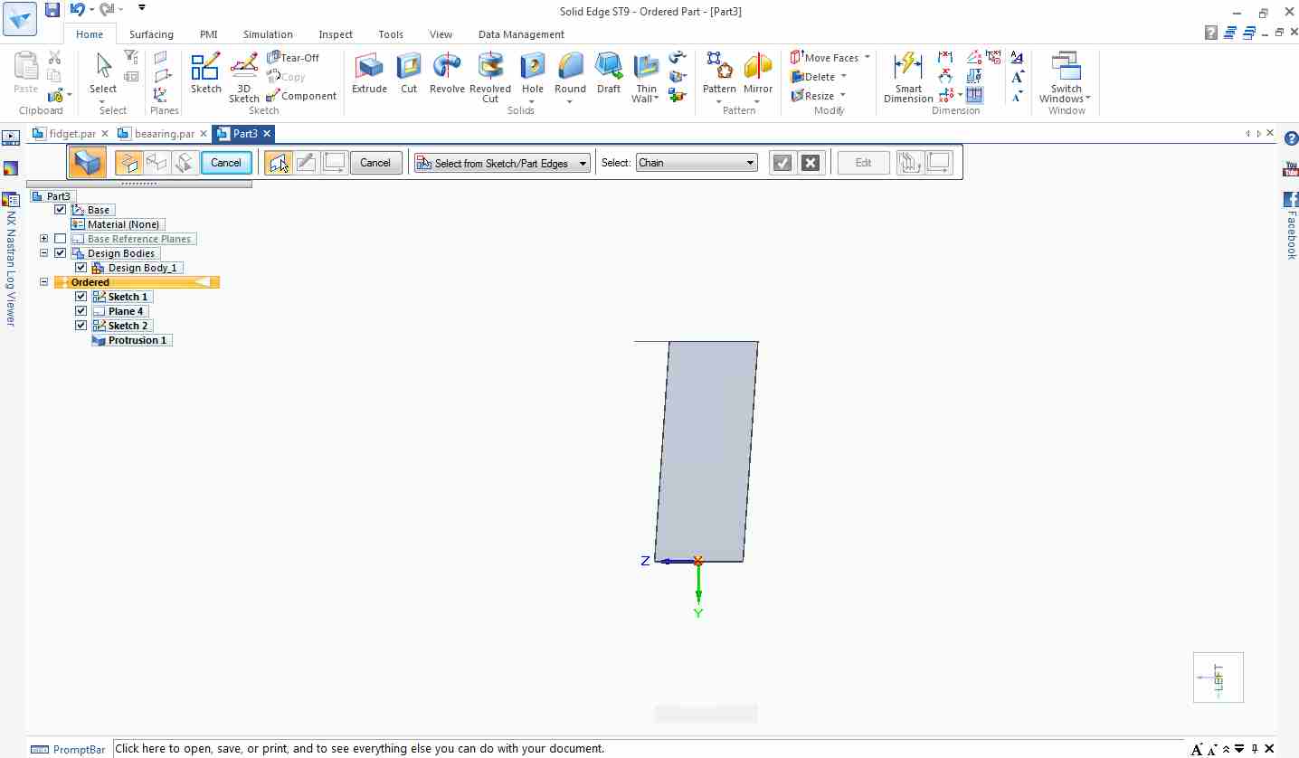
The Datum plane has been taken to made rectangle at other angle. I joined both the rectangle by sweep command.
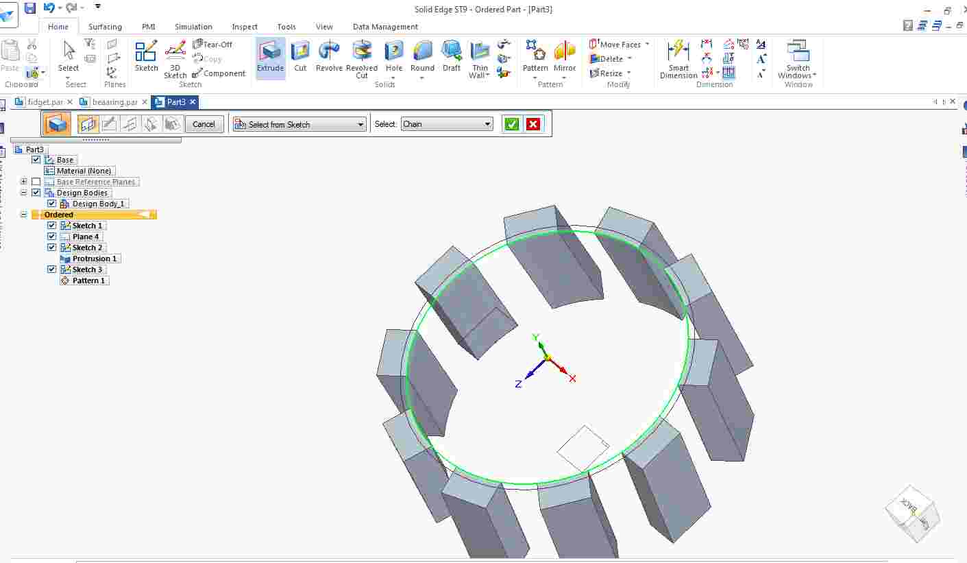
Then I use the pattern command to make 10 pattern of that sweep.
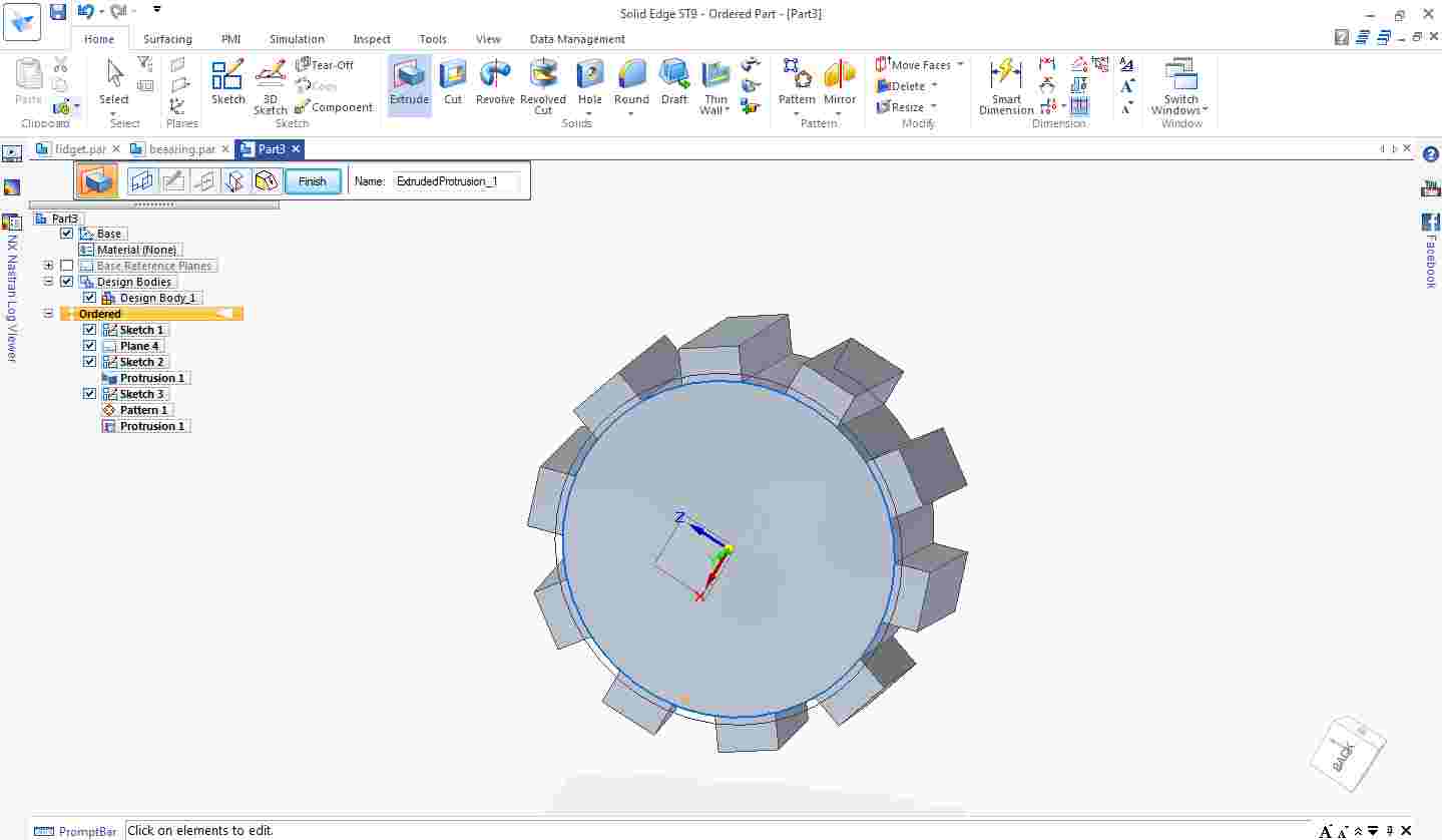
Then combined all the pattern with cylindrical block.
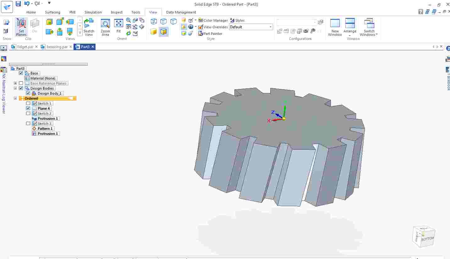
Here gear is ready
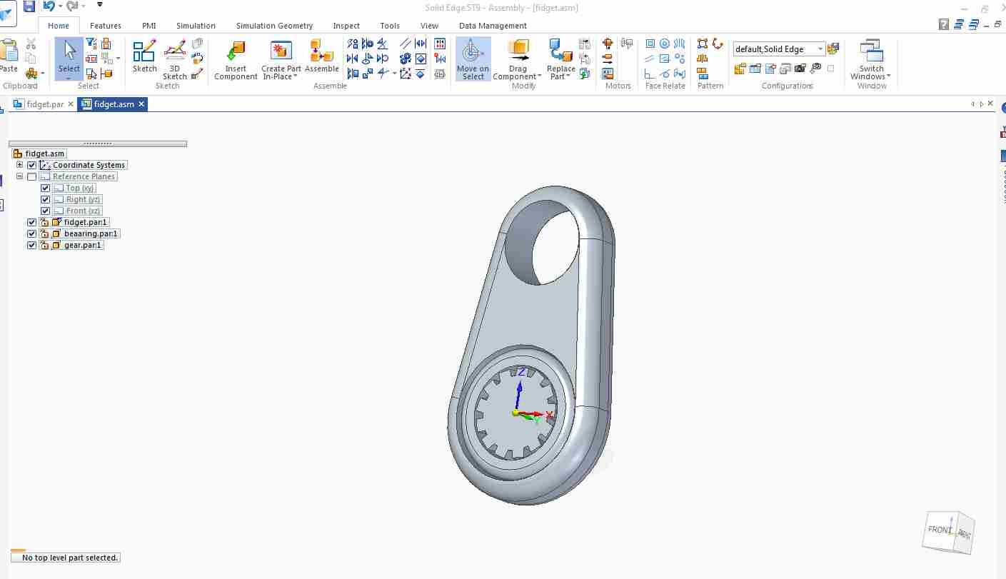
This is the final assembly.
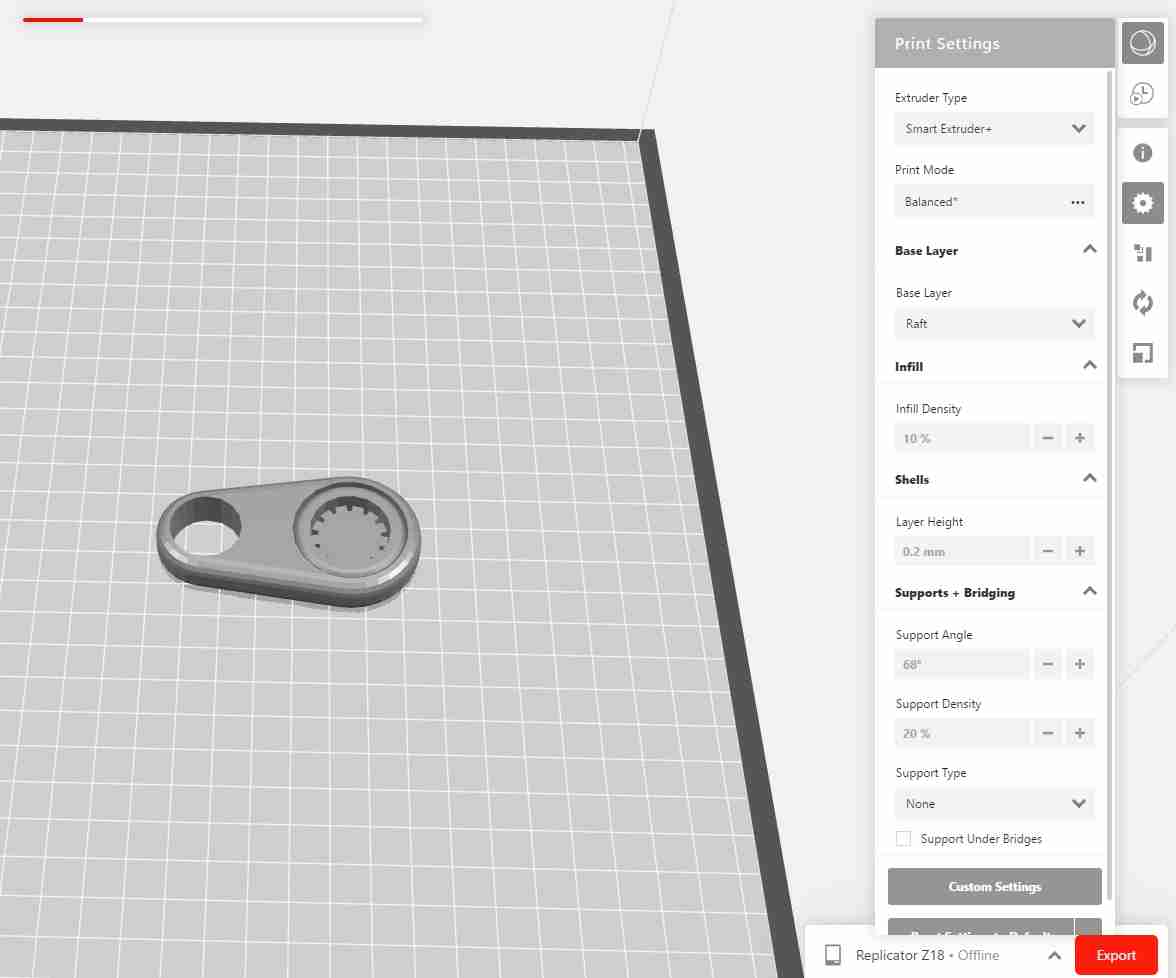
I used Makerbot print software for slicing the object.
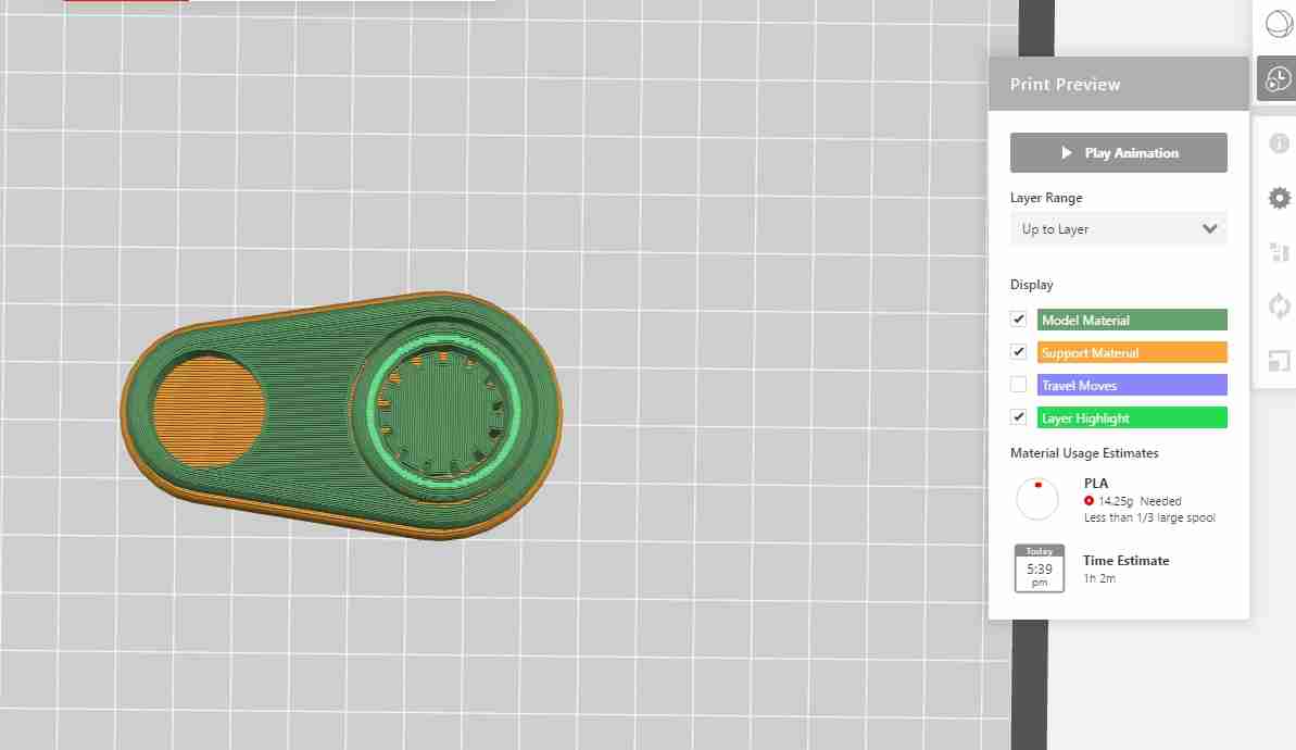
I used setting: Infill:10%
Layer Height:0.2 mm
Material Used:14.25 gm
Time Estimate: 1h 2m
Raft : on
Support : Off
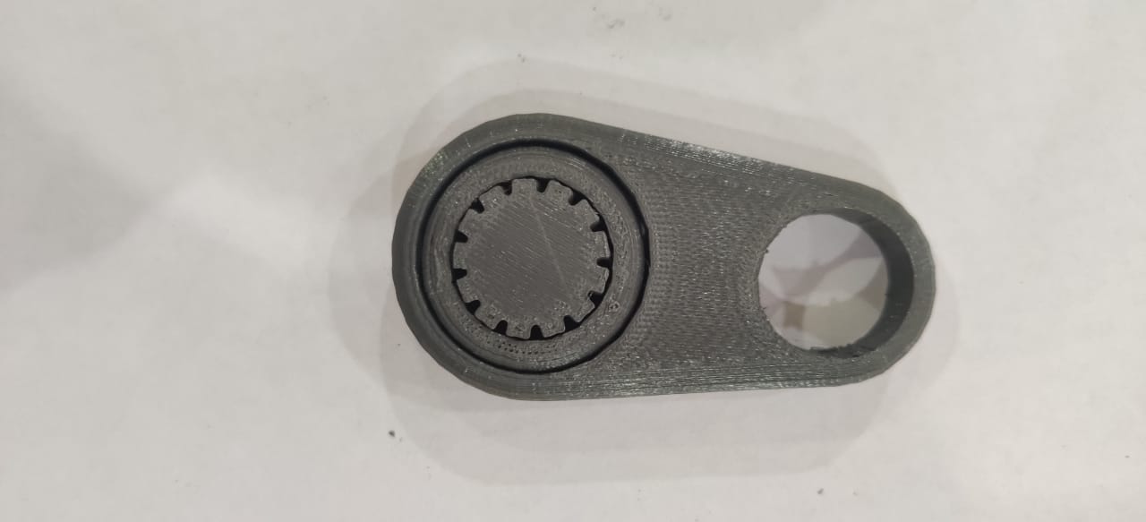
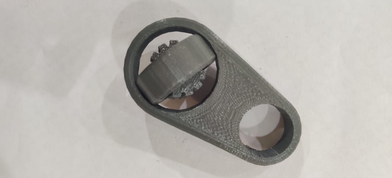
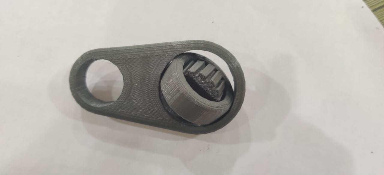
This is 3D Printed Fidget Bearing.
Post Processing:
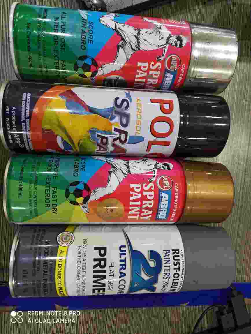
I used Hydrodipping Technique for Post processing.
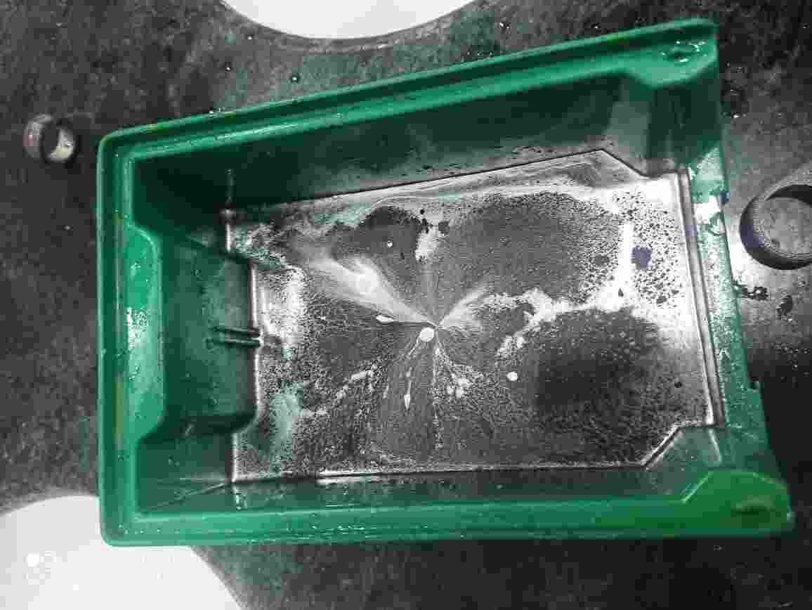
This is showing the tub having cold water and layer of spray color used in hydrodipping technique.
This is the result which comes out after the process.
It is looking different and this process works well.
Conclsion :
This fidget bearing can not made by 2.5D milling process as parts of this are nested in other part.
- 1. In traditional manufacturing process like milling, drilling cutting, We can not make complex shapes.
- 2. Through 3d priting we can manufacture the objects which are not possible by 2.5 D milling machine.
- 3. In rapid prototyping we can test shapes which will b manufactured costly by other pocesses.
- 4. The weight of part which will be done by 3D prinitng can be alter according to the strenth required.
- 5. There is no wastage occur in case of 3D printing process.
Advantages of 3D Printing over other manufcturing process
- 1. In case of fused Deposition Modelling, There is very limted choice of material, very few materials have the property to melt.
- 2. If there is so much support material, post procesing is time taking and manual task.
- 3. Accuracy and finishing will depend on the printer used for 3D prinitng. Different printers produce different quality product and it may vary from actual design.
- 4. Most of the materials used in 3D printing are not eco-friendly.
Limitation of 3D Printing
3D SCANNING
3D scanning consists of turning a real-life object, such as an action figure, a room, an entire building, or anything that has three dimensions and can be scanned, into a virtual 3D model. There are two common types of 3D scanning, the first one, as the name already says, “3D Scanning”, and the second one “Photogrammetry”.
3D Scanning utilizes a 3D scanner, which takes a video, of sorts, of the object. This 3D scanner can be any sort of camera with an infrared sensor to be able to measure the depth of field.
Photogrammetry consists of taking multiple pictures at different angles of an object.
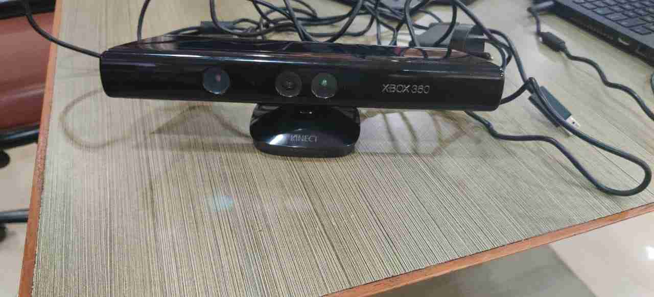
This is the Kinect X-BOX 360 sensor scanner,which is used for 3D scanning.
This is the tutorial which I followed to install the software.
There are two softwares which is downloaded to get the scanning done.
1. This is the Kinect software and driver link Kinect Software
2. This is the link to download the Kscan 3D Software- Kscan3d Software I used Kscan3D software to scan my one partner and one object.I followed this tutorial.
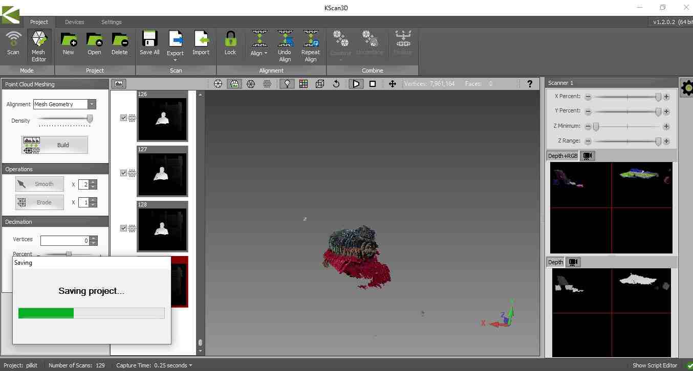
Thses are the attempts which was done by me and my fabmate to scan Pulkit with Kscan 3D
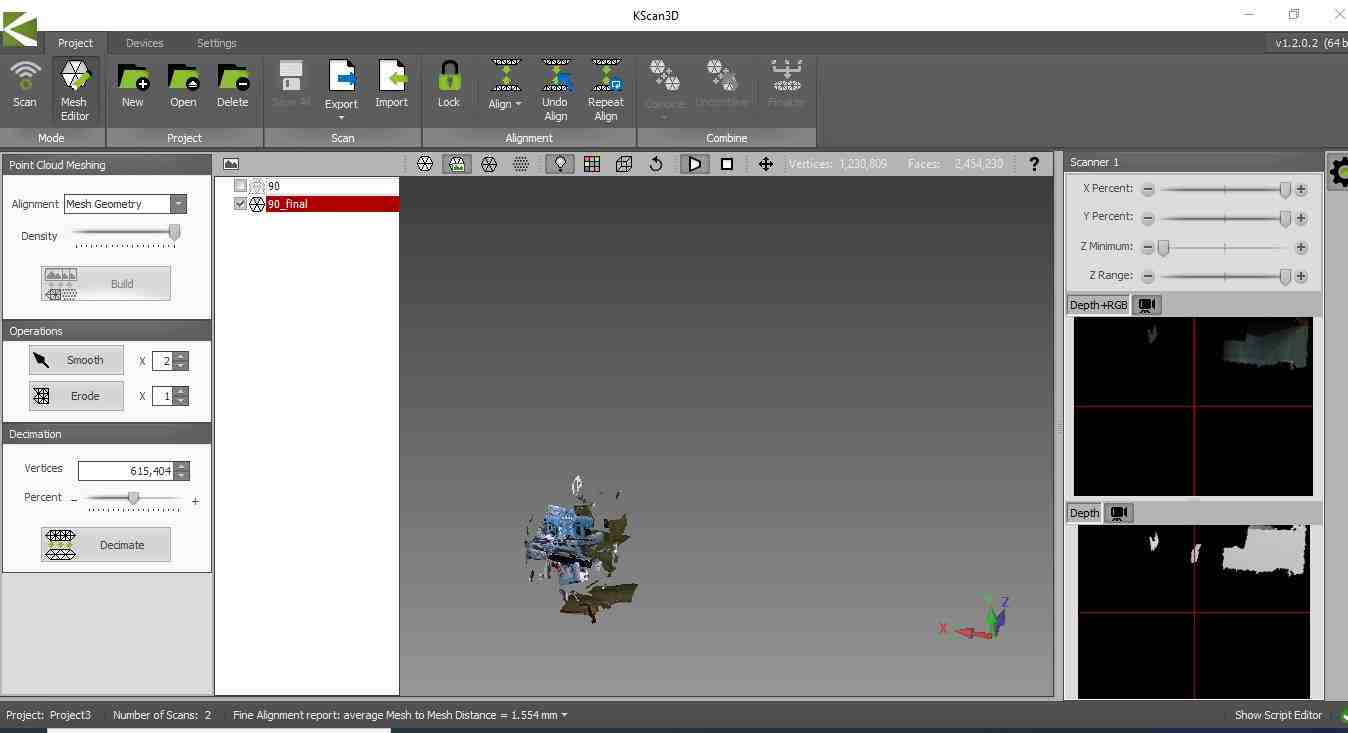
Unfortunately we did not able to get the desired result.
The photos took by the scanner did not combined by the software as there should be a rotary table or stand on which we could keep the Kinect scanner so that we can easily captured the images from every angle possible.As we put it on standstill table while we were capturing the images the software did not get optimum photos in order to get a perfectly shaped body.After various attempts we moved on to mobile app for scanning process.
Qlone
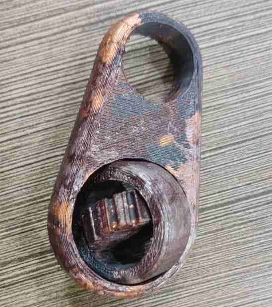
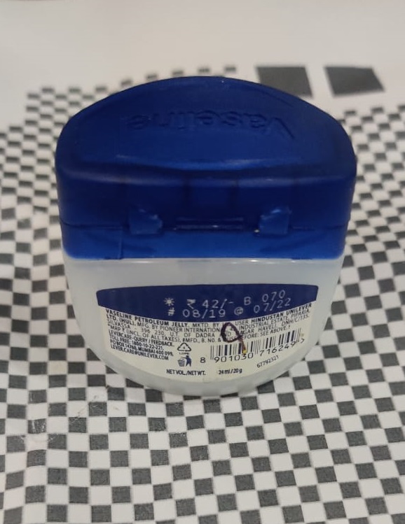
I used mobile app Qlone to scan one of the 3D Printed Stool part available in my lab.
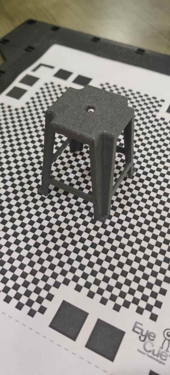
The black and white box mat is required to scan the object through Qlone mobile app.We can scan the maximum size upto the size of mat.So we took print out on A4 sheet.
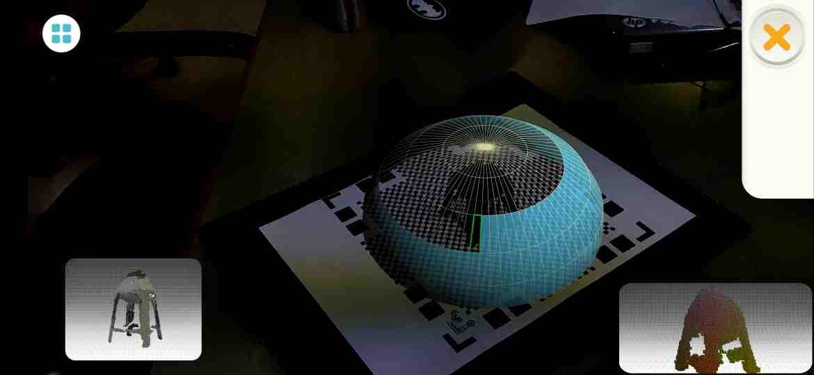
In this process, by continously holding the mobile phone, we have to rotate around the part which we want to scan.I put a plate below the mat to rotate the mat easily.
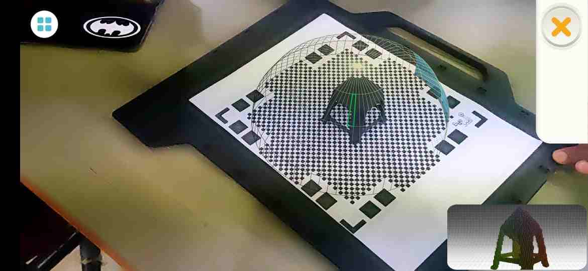
As shown in figure, we have to complete the blue lines in the top, bottom an middle layer of dome to complete the scanning process.
The results are not that much satisfying as we have to continously move our hand and have to do rotation manually, so the quality of scan must depend on the hand rotation as well it is a mobile app did not give that much of accuracy required
It does not give the acceess to export the file in STL format which is required for 3D Printing, so I exported it in .gif format.
I tried one other object which is having different color as previous one had grey color.As suggested by my global instructor Salman, the Qlone is based on photogrammetry, it needs features in the object to better identify dimensions and topology.
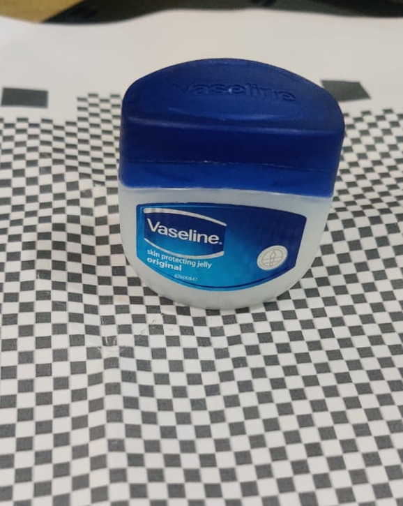
This shows the textured object.It comes out like this.
It scan object better with lesser height as compared to object with more height.So large size mat is required for greater height.
3D scanning is used for Reverse Engineering because through reverse egineering we can produce the 3D object without actually getting its design file.
So 3D scan able us to get STL file of the object and implementation will be done on it. There is no need to get the basic design in order to produce substitute.


This work by AFSHA is licensed under a Creative Commons Attribution-ShareAlike 4.0 International License.
Based on a work at http://academany.fabcloud.io/fabacademy/2020/labs/akgec/students/afsha.