Interface and Application Programming
#Assignment
Individual Assignment
>>>>>write an application that interfaces a user with an input &/or output device that you made
Group Assignment
>>>>compare as many tool options as possible
MIT App Inventor
GUI
Graphic User Interface is a desktop application which helps you to interact with computer.It is a type of interface that allows users to interact with electronics devices through graphical icons and visual indicators.
I tried from basics as I dont have my board..So I first go with basics and first made two apps.
First App
Here are the snapshots Starting with Create Apps, we need to login to MIT App Inventor using our gmail account. Once we login to the cloud, we need to create a new project.
BALL BOUNCE
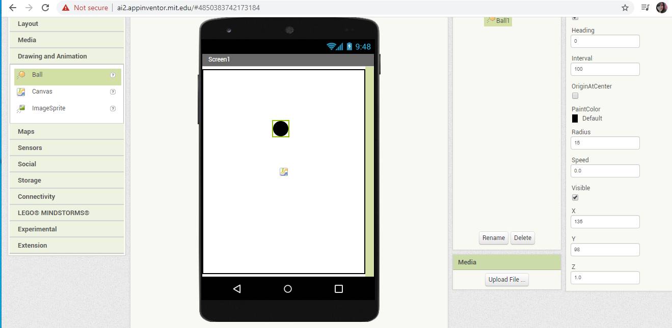
I select Ball form Drawing and Animatioin tab on left.
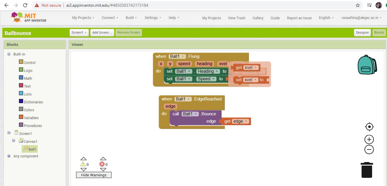
After Designer,You can set the blocks according to app requirement.
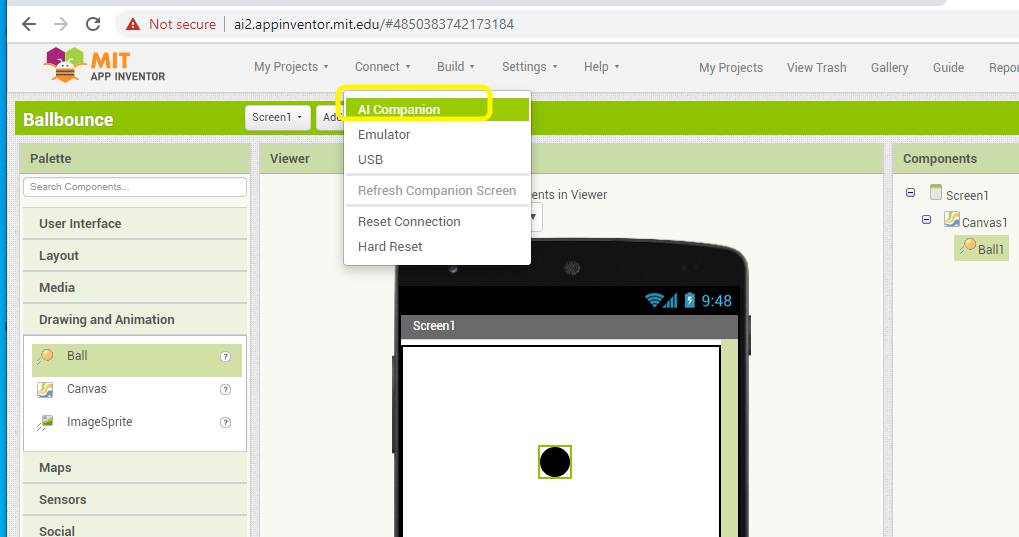
You can Export the app with AI companion
You can export it to your phone as an app in the form of .apk
Below is the video of trial of Ball bounce App
Second App
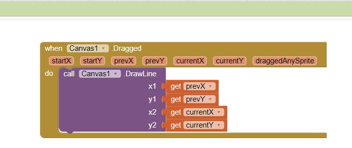
Drawing APP
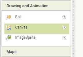
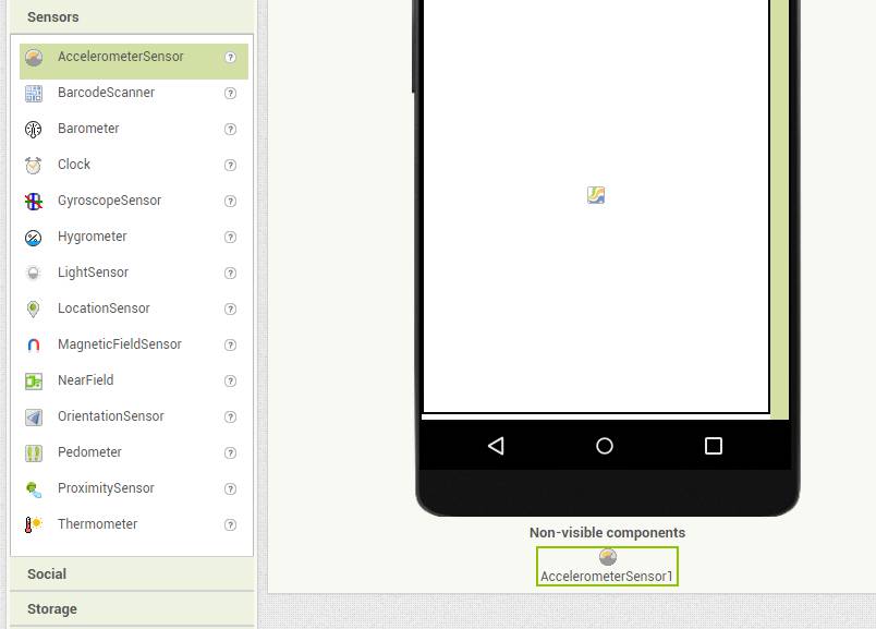
I have taken one canvas to draw something on it from Drawing and Animation Tab
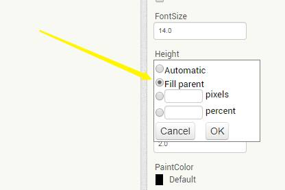
Filled the whole screen with it and also added accelerometer from Sensor Tab
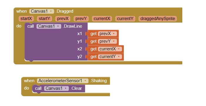
Below is the video for trial of Drawing App in which i wrote Fab Academy on my phone screen and I recorded it with phone.
TO CONTROL ARDUINO LED WITH BLUETOOTH
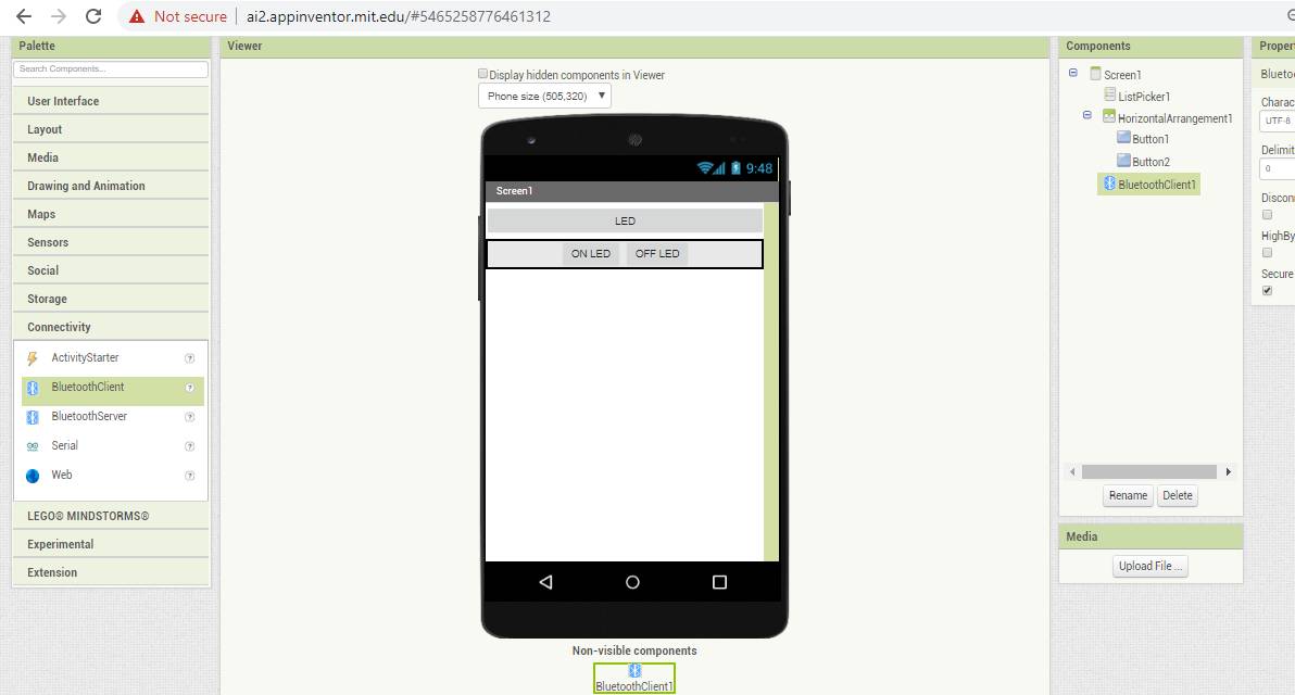
From Pallete I have taken List Pickers and named it as LED.
You can also change the dimension of the box and alignment of the box as well as the text settings.For connectivity, I selected Bluetooth as i want send data from my app to board with bluetooth module.
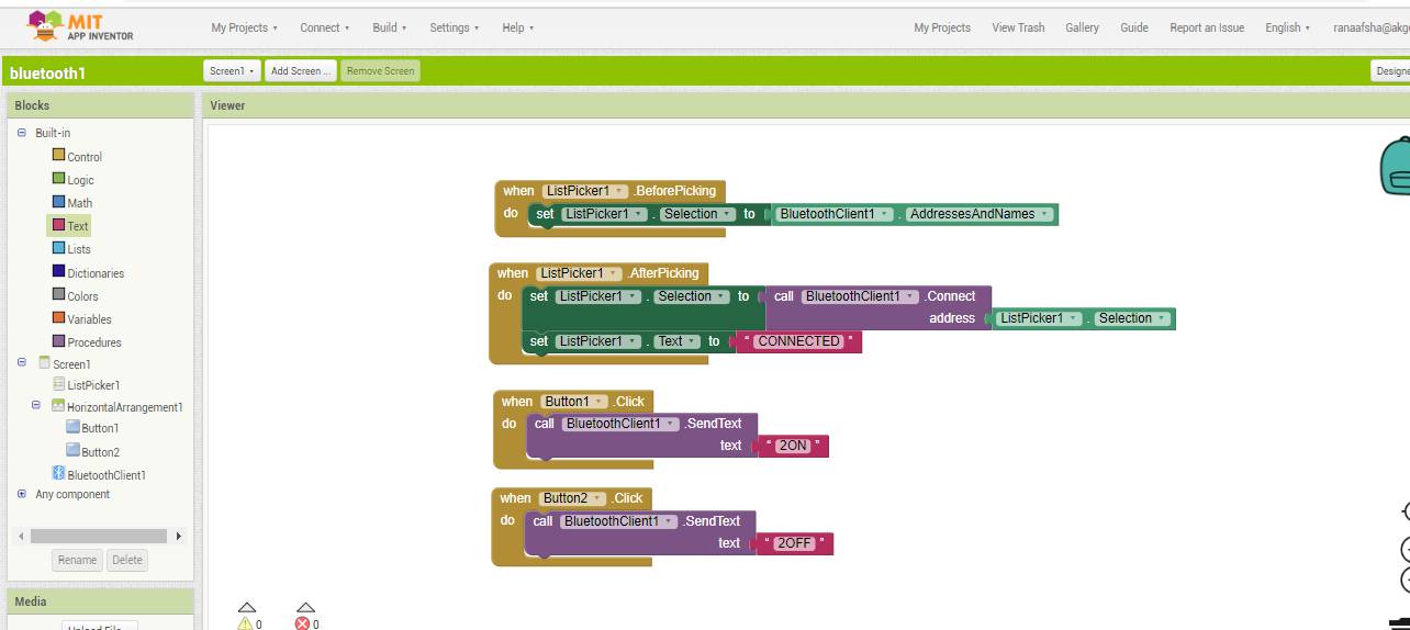
Once your designer get ready, You have to go to Blocks on top right corner to set the programming for app in terms of block
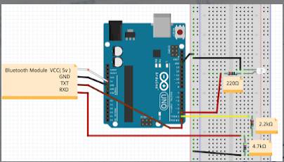
This is the image showing how to conect bluetooth module with Arduino so that you can control the LED of Arduino with MIT App.
After Lockdown
As the assignment for this week was to make an app and communicate it with your output and input device board.I made an app earlier in order to switch on and off the LED of Board.
I followed this turtorial to work upon this
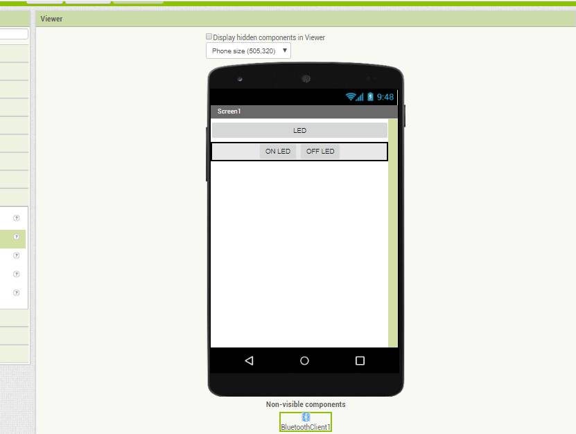
Change in APP
>Moving on forward I want to change it little bit.
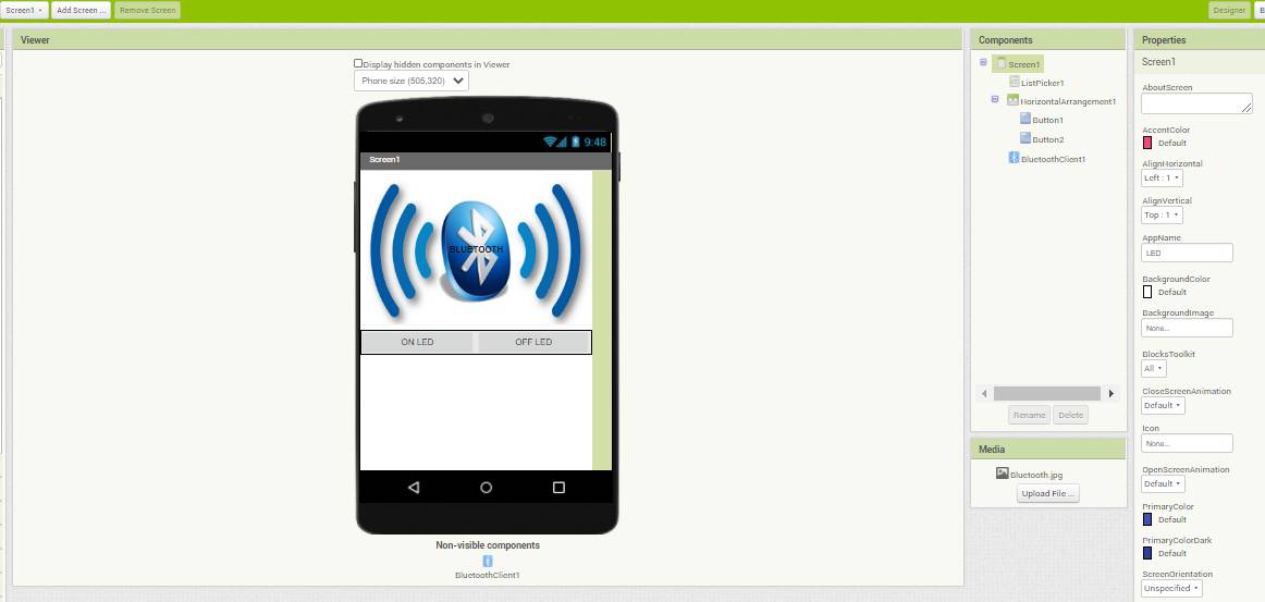
I added one image of bluetooth as an icon.
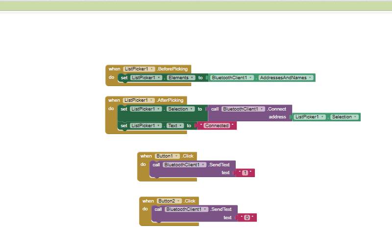
With the help of list picker and changing their values You can simply make an app.
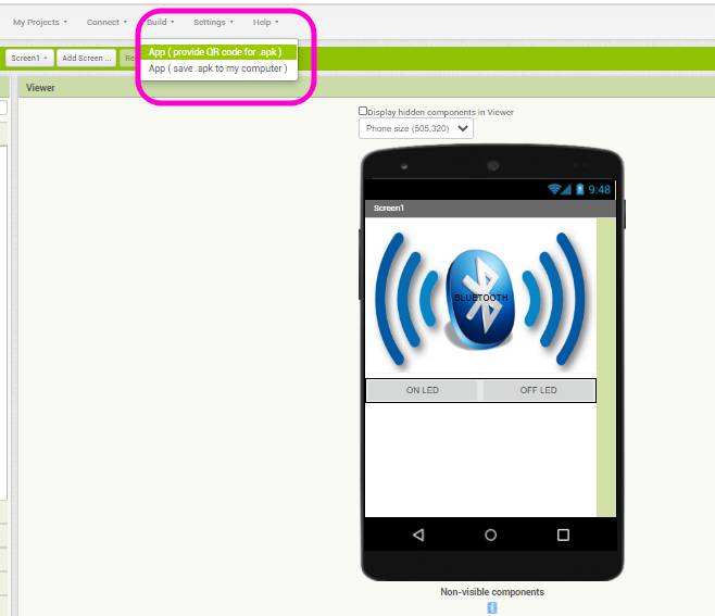
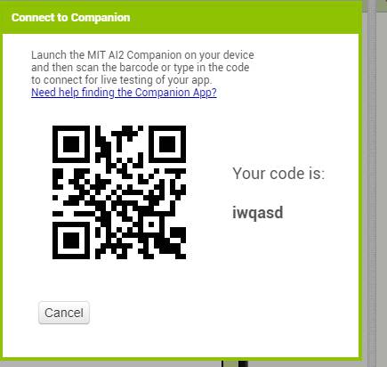
Click on Build and APP(provide QR Code for .apk)
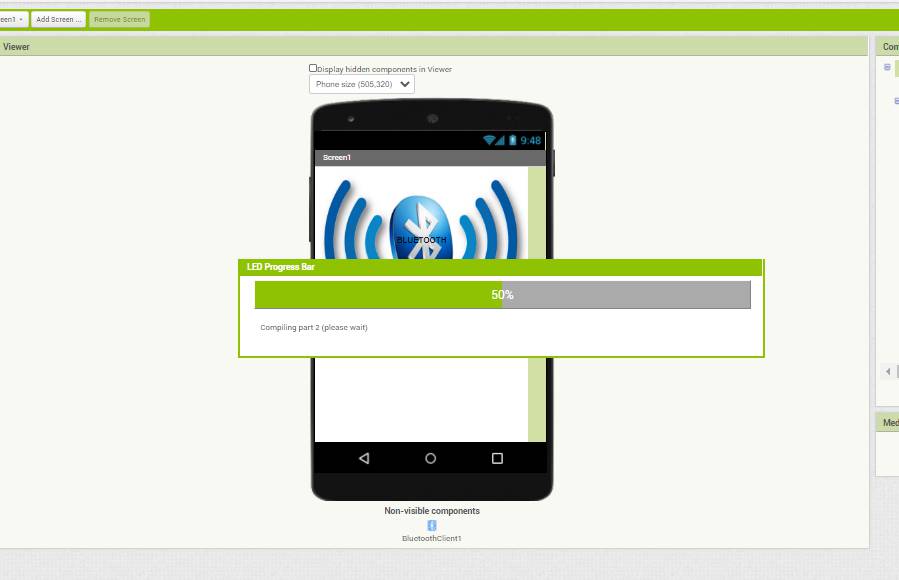
It will show this progress bar for compiling it and after it became 100 percent,The code is generated.
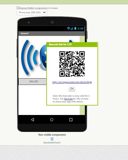
You have to scan it with you phone Mit App

This is the interface for App to scan this code on your phone.
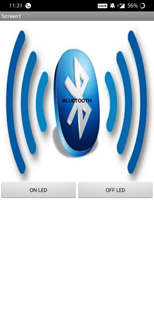
After getting .apk file.The app look like this on my phone.
Controlling Arduino LED with MIT APP
I used this tutorial for using LED with MIT APP
First I have connected LED on pin 13 of Arduino and HC-05 Bluetooth module pins(RX TX GND VCC ) to (TX RX VCC GND ) of arduino and uploaded the program given below.Open the app and click on Bluetooth icon and it shows list of bluettoth devuces You have to pair it with HC-05 device Once it get connected it shows connected on app.
Now you are ready to control led with your app.
Code for Arduino
When Arduino read 1 it will turn on LED and when it read 0it will turn of LED.
char Incoming_value = 0;

void setup()
{
  Serial.begin(9600);
  pinMode(13, OUTPUT);
}

void loop()
{
  if(Serial.available() > 0)
  {
    Incoming_value = Serial.read();
    Serial.print(Incoming_value);
    Serial.print("\n");
    if(Incoming_value == '1')
      digitalWrite(13, HIGH);
    else if(Incoming_value == '0')
      digitalWrite(13, LOW);
  }
}
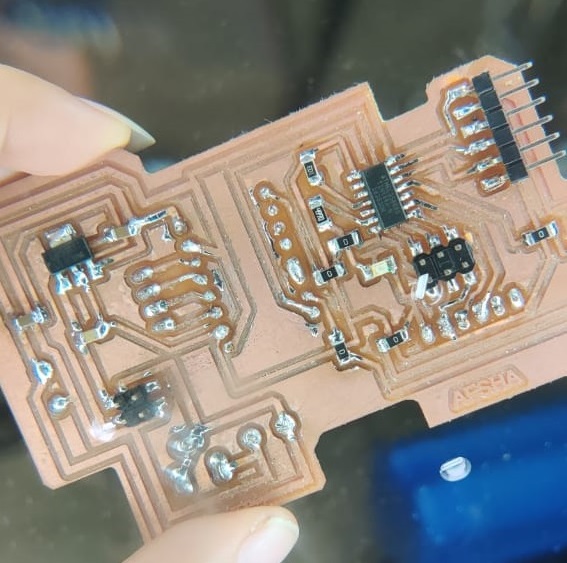
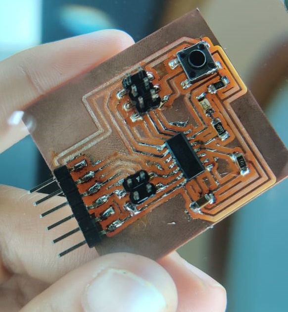
After experimenting with Arduino.I switched to my output Device Board.In this board LED is connected to pin 7 of Attiny 44.
Above is the video you can check I am controlling with MIT APP.
Below is the video showing I have connected vcc and gnd of bluetooth module to vcc gnd of avr isp vcc gnd and rx tx to ftdi RX TX as there the traces of vcc has distorted thats why I removed two pins from there.
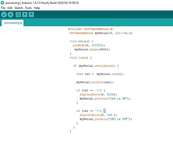
Code for Board
For serial Communication between Board and App , Bluetooth module was used and it is importatnt to connect RX and TX of blueetoth module to TX RX of Attiny in my case Itook 0 and 1 as RX and TX.You have to mention it in code otherwise it will not work
    //created by: Afsha
    #include "SoftwareSerial.h"
    SoftwareSerial mySerial(0, 1); // RX, TX
    char Incoming_value = 0;

    void setup()
    {
      mySerial.begin(9600);
      pinMode(7, OUTPUT);
    }

    void loop()
    {
      if(mySerial.available() > 0)
      {
        Incoming_value = mySerial.read();
        //mySerial.print(Incoming_value);
       // mySerial.print("\n");
        if(Incoming_value == '1')
          digitalWrite(7, HIGH);
        else if(Incoming_value == '0')
          digitalWrite(7, LOW);
      }
    }
PROCESSING IDE
Processing is a flexible software sketchbook and a language for learning how to code within the context of the visual arts.
I used this tutorial to learn how can I control Arduino with processing.
To download Processing go here: Processing Download page
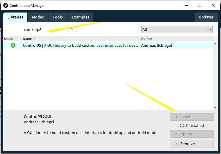
When you click on download Processing, it downloads one zip file. Unzip that file and inside the unzipped folder you will find Processing application. And to run Processing, double click on that icon. To install new library from menu, go to: Sketch -> Import Library... -> Add Library... ADD CONTROLP5 and install it..
I referred the code below from Hardik Rathod hackster.io and experimented with it.
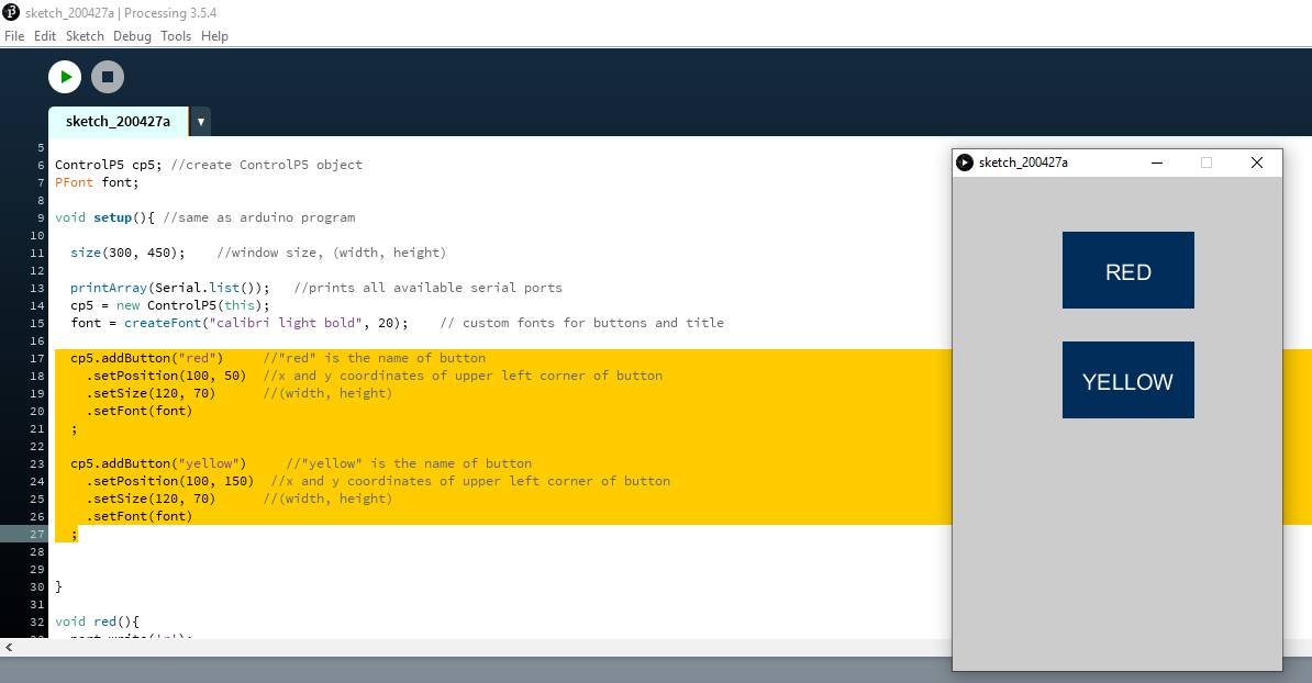
You can add one or more than one button and also manage the size of button
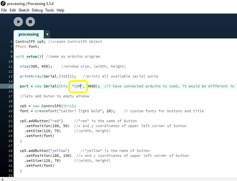
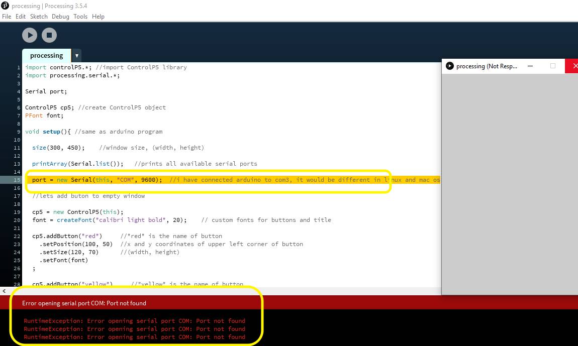
If COM PORT is not connected to Arduino for serial communication,It will show this error.
Processing Code
//Code by Hardik Rathod
import controlP5.*; //import ControlP5 library
import processing.serial.*;
Serial port;
ControlP5 cp5; //create ControlP5 object
PFont font;
void setup(){ //same as arduino program
size(300, 450); //window size, (width, height)>
printArray(Serial.list()); //prints all available serial ports
port = new Serial(this, "COM", 9600); //i have connected arduino to com3, it would be different in linux and mac os
//lets add buton to empty window
cp5 = new ControlP5(this);
font = createFont("calibri light bold", 20); // custom fonts for buttons and title
cp5.addButton("red") //"red" is the name of button
.setPosition(100, 50) //x and y coordinates of upper left corner of button
.setSize(120, 70) //(width, height)
.setFont(font)
;
cp5.addButton("yellow") //"yellow" is the name of button
.setPosition(100, 150) //x and y coordinates of upper left corner of button
.setSize(120, 70) //(width, height)
.setFont(font)
;
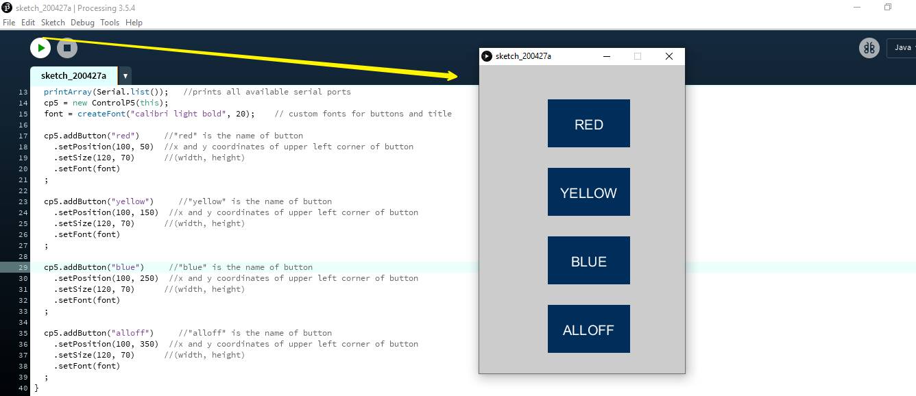
cp5.addButton("blue") //"blue" is the name of button
.setPosition(100, 250) //x and y coordinates of upper left corner of button
.setSize(120, 70) //(width, height)
.setFont(font)
;
cp5.addButton("alloff") //"alloff" is the name of button
.setPosition(100, 350) //x and y coordinates of upper left corner of button
.setSize(120, 70) //(width, height)
.setFont(font)
;
}
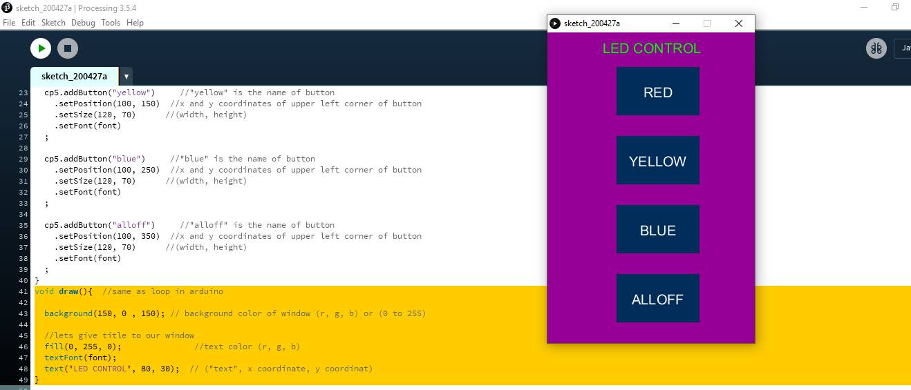
void draw(){ //same as loop in arduino
background(150, 0 , 150); // background color of window (r, g, b) or (0 to 255)
//lets give title to our window
fill(0, 255, 0); //text color (r, g, b)
textFont(font);
text("LED CONTROL", 80, 30); // ("text", x coordinate, y coordinat)
}
//lets add some functions to our buttons
//so whe you press any button, it sends perticular char over serial port
void red(){
port.write('r');
}
void yellow(){
port.write('y');
}
void blue(){
port.write('b');
}
void alloff(){
port.write('f');
}
Arduino Code
  //Code by Hardik Rathod
    void setup() {

        pinMode(10, OUTPUT);   //set pin as output , blue led
        pinMode(11, OUTPUT);   //set pin as output , red led
        pinMode(12, OUTPUT);   //set pin as output , yellow led

        Serial.begin(9600);    //start serial communication @9600 bps
        }

      void loop(){

        if(Serial.available()){  //id data is available to read

          char val = Serial.read();

          if(val == 'r'){       //if r received
            digitalWrite(11, HIGH); //turn on red led
            }
          if(val == 'b'){       //if b received
            digitalWrite(10, HIGH); //turn on blue led
            }
          if(val == 'y'){       //if y received
            digitalWrite(12, HIGH); //turn on yellow led
            }
          if(val == 'f'){       //if f received
            digitalWrite(11, LOW); //turn off all led
            digitalWrite(12, LOW);
            digitalWrite(10, LOW);
            }
          }
        }
Above is the example for processing which I want to tried for four LEDs but after lockdown I made it for one LED and applied it on my Hello Echo Board which I made in Electronic Design Week.
Functions used explained-- (size(300, 400))-to create a window of any size
- (background(255, 255,51))- To give background Color
- void/ draw()- to draw on the window
- cp5.addButton<- using CP5 library to add a button
- .setPsoition and .setSize- To set the position of the button and size of it
To connect it with our cicuit we need to define the COM port and the BaudRate in the code - Initialize the Serial port
Serial port;
Give the com port and set baudrrate i.e. the speed of data transmission
port = new Serial(this, "COM(Number)", 9600);
To write the Data on the port
port.write('1');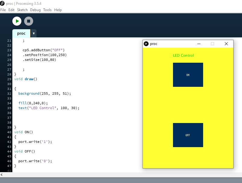
I used 255,255,51 RGB values for background yellow color.
First I used Arduino to use Processing.
I connected Arduino VCC GND RX TX with VCC GND TX RX of my Hello Echo Board and uploaded the following Arduino Code on my board.
Arduino Code
Conclusion
Its all new experience for me. I explored little but in future will work more on it.

