14. Networking and communications
Design, build, and connect wired or wireless node(s) with network or bus addresses
What will it do?
During this week, I want try to use the bluetooth technologie. My goal is to learn more about it and use it for my final projects.
I looked some videos about bluetooth 5 protocols and the nrf52.
And I read the datasheet of the BMD-350 that we have in our lab and I saw this quick overview.
The BMD 350
I spend some time to read and understand the datasheet of the BMD-350.
It's an amazing microcontroller, based on the nrf52, he's certified for bluetooth 5 protocole, he has 512kB embedded flash memory, 64kB RAM, and 32 GPIOs.
But Unfortunately, it was too small to design a board with our materials, so I decide to give up this microcontroller, and maybe take an order for another package bigger than this one.
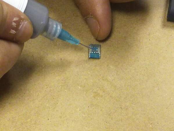
BC-04 BK
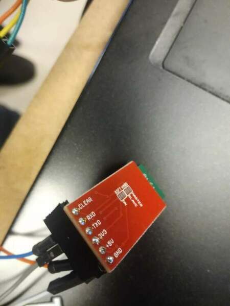
So I decide, to use a bluetooth module BC-04 BK, it's like the HC04, he's implement the bluetooth 4 protocole, it can be a slave or a master.
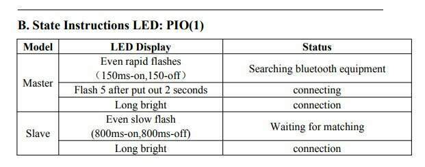
For me, in a first time, I will just start by the slave mode. The BC-04 has a led integrated, a led have many state discribe in the datasheet.
Try serial communication with BC-04 <-> FTDI
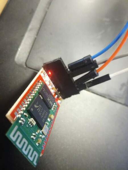
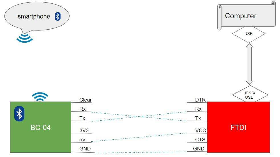
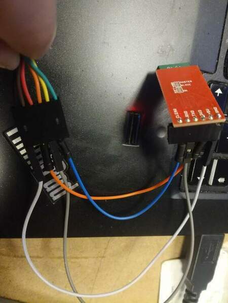
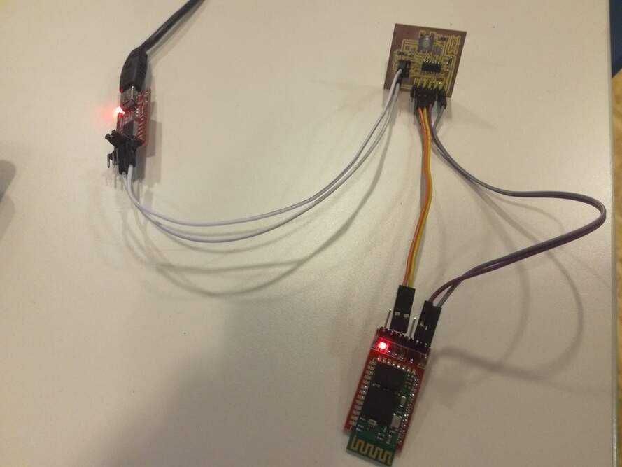
To test if the module works BC-04 works, I connect directly the FTDI with the BC-04, the connection is really easy as you can see in the bellow. For the BC-04 as slave mode, the only need is to connect 4 pins (VCC, GND, Tx and Rx) as you can see in the bellow schematics that I maid. I did also this first test, to split the debugging of this assignement. Indeed, when I know that I'm able to communicate from the module to the FTDI, I will easly replace my FTDI module with one of the board that I maid during previous weeks.
Then I installed the HC05 android app, to communicate with the module bluetooth. The application is usefull, because I can choose what kind of data (HEX or ASCII), and it's possible from the application to configure and save special button and they are a terminal to send what I want.
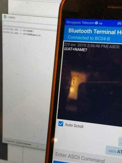
The communication work as well, unfortunally, I can't use the AT commands by this way (need to solder jumper). So I can't update the name of the module, but it's ok for this exercise.
Create application crazyLeds
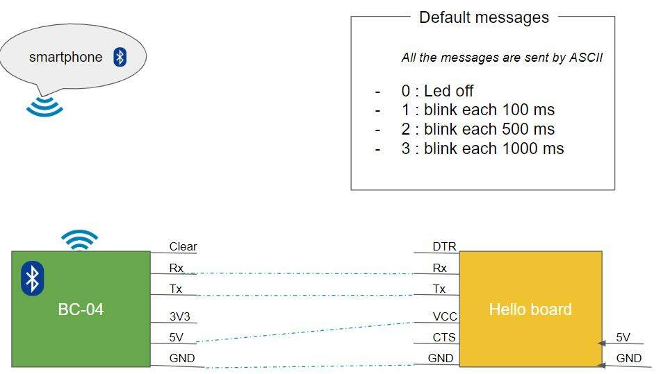
I decide to write an application for my hello board that I maid in week07, I call it crazyLeds. The idea of this application is to play with the led of the board and make 3 modes of blinking. And control the board from the application that I tested on the top. So here you can see diagram that I maid to explain the schematics :
So then I make a program for what I want to do. I decide to use the function millis instead of delay, to prevent the lost messages. Indeed, when the microcontroller execute a delay method, he suspend all others tasks. It can be anoying if I want to mange many task with differents timelines. So I decide to use millis, for this advantages and to be familliar with it. I based my code using the follow arduino example.
/* crazy led

Serial communication : (in ASCII)
0 : Led off
1 : blink each 100 ms
2 : blink each 200 ms
3 : blink each 1000 ms

 Author : Madjid AIT SI AMER
*/
#include "SoftwareSerial.h"


const int ledPin =  A7;// the number of the LED pin
const int btRx = 0;
const int btTx = 1;

// Variables:
int ledState = LOW;          // ledState used to set the LED
int mode = '0'; // by default, we set the mode to 0 the led is off

long intervalMode = 0;
// Generally, you should use "unsigned long" for variables that hold time
// The value will quickly become too large for an int to store
unsigned long previousMillis = 0;        // will store last time LED was updated

// constants won't change:
const long interval = 1000;           // interval at which to blink (milliseconds)
SoftwareSerial bluetoothSerial(btRx, btTx);


void setup() {
  // set the digital pin as output:
  pinMode(ledPin, OUTPUT);
 // Bluetooth serial
  pinMode(btRx, INPUT);
  pinMode(btTx, OUTPUT);
  bluetoothSerial.begin(9600);
}

void loop() {
  // here is where you'd put code that needs to be running all the time.

  // check to see if it's time to blink the LED; that is, if the difference
  // between the current time and last time you blinked the LED is bigger than
  // the interval at which you want to blink the LED.
  unsigned long currentMillis = millis();
  if (mode != '0'){
    // the blinking part
    if (currentMillis - previousMillis >= intervalMode) {
      // save the last time you blinked the LED
      previousMillis = currentMillis;

      // if the LED is off turn it on and vice-versa:
      if (ledState == LOW) {
        ledState = HIGH;
      } else {
        ledState = LOW;
      }

      // set the LED with the ledState of the variable:
      digitalWrite(ledPin, ledState);
    }
  }
    if (bluetoothSerial.available()) {
      int cmdLed = bluetoothSerial.read();
      // use simple cote to not convert caracter from ascii to decimal
      if (cmdLed == '0') {
          mode = 0;
          previousMillis = currentMillis;
          // Need to set ledState to LOW, because if not, the led can be considered as off but the reality can be the opposit, example: the user send stop  when the led was HIGH,the blinking stopped but not the LED
          ledState = LOW;
      } else if (cmdLed == '1') {
          mode = 1;
          intervalMode = 100;
           previousMillis = currentMillis;
      } else if (cmdLed == '2') {
          mode = 1;
          intervalMode = 500;
           previousMillis = currentMillis;
      } else if (cmdLed == '3') {
          mode = 1;
          intervalMode = 1000;
           previousMillis = currentMillis;
      } else {
          bluetoothSerial.print("Not recognize this mode ");
          bluetoothSerial.println(mode);
      }
  }

}
In the HC05 android app, I start by connecting to HC05 module. To connect on it, I made a scanning on the app using the button on the right top of the application. Then the list of device available is displayed, you need to select BC04-B, then for the fisrt connection the application ask for the password, and then by default the password is 1234.
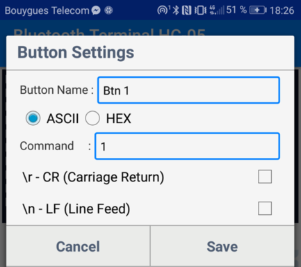
Then I defined the 4 buttons modes. Each time I send ASCII characters (0: off, 1: 200ms interval blinking, ...). It's usefull function to store command, and make testing faster. In this settings, you can decide to add special characters in the end of serial message, but I didn't manage it in my code, so I disabled the options.
Using the Arduino IDE, I compiled and uploaded the code on my Helloboard. Then using my FTDI module I gived the 5V and GND from SPI pins, and I connect as describe on the top the hello board with the HC-04 module.
How it works:
Files
They are no designs files for this week.