13. Applications and Implications
This week we are supposed to propose a final project masterpiece that integrates the range of units covered, answering: What will it do? Who’s done what beforehand? What will you design? What materials and components will be used? Where will come from? How much will they cost? What parts and systems will be made? What processes will be used? What questions need to be answered? How will it be evaluated?
My project should incorporate 2D and 3D design, additive and subtractive fabrication processes, electronics design and production, microcontroller interfacing and programming, system integration and packaging Where possible, I should make rather than buy the parts of your project. Projects can be separate or joint (I am alone in my lab so I don’t think I’ll be doing a joint project) but need to show individual mastery of the skills, and be independently operable.
My final project proposal
My final project is to create a line of children’s toys that can be made inexpensively in a FabLab. Toys are among the first “brain teasers” we meet as children. Toys should make us wonder: What can I do with this? Toys should spark imagination and play. Play is the best way to learn. Toys should bring children joy! They should be inexpensive and made from sturdy stuff so they can take a beating. Children should be able to be rough with a toy (within reason) without it breaking. That’s one of the reasons I like wooden toys over plastic, although I see the benefit of a plastic toy if you need to wash the toy frequently.
Final project conundrum
One of the most important goals of my toy project was to make them simple and not electronic so that they are very inexpensive and can be given to children without a concern about needing a new battery or plugging into an electric socket. How do I do that and still incorporate all of the electronics we’ve been learning?
Final project planning
I have been planning my final project since the beginning of this course, but I didn’t understand then that the final project has to incorporate all of the different things that we have learned. I plan to make a dollhouse - at least one full room. This is my preliminary plan for using all of the equipment in our FabLab:
- 3D print small items in the dollhouse such as lighting fixtures.
- Vinyl cut some intricate decoration such as the vines of a plant.
- Use the large format printer to print wallpaper.
- Laser cut furniture
- use electronics for lighting the fireplace
Final project sketch
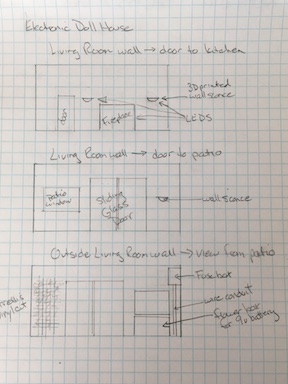
Final project blueprint
- Sliding glass door - maybe incorporate electronics that is a burglar alarm
- Fireplace - use clap on clap off board (from the sound electronic board) to turn the fireplace LEDs on
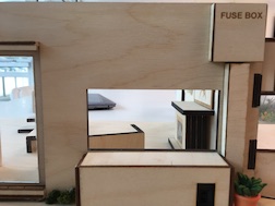
- Fusebox - make an electronic board that turns on all of the sconce light fixtures with an on/off button
Final project timing
Final project due date: 2nd week of June Electronics finish date: 1st week of June furniture (all laser cuts) finish date: before June 1 walls, doors, details: before May 25
Copied from Final Project Page
Project Requirements:
- 2D and 3D design (design one room of the house and the furniture)
- additive and subtractive fabrication processes (use the laser cutter and 3D printer for furniture)
- electronics design and production (create an electronic component into the lighting system)
- microcontroller interfacing and programming (make a clap-on, clap-off pcb system)
Demonstrating Mastery:
- What will it do? - It will be a toy that will allow children to use the imagination to create stories
- Who’s done what before? Dr. Marije Kanis worked on projects to help children learn. She must have used doll houses in her work but did not actually build one for her fabacademy learning. I did find this interesting article on her website, though, about using doll houses to test what people think about smart houses. “Using an Interactive Dollhouse to Demonstrate Ambient Interactions in the Home”
- What will I design? - I will design one room of a dollhouse with walls, ceiling, floor and furniture
- What materials and components will be used? - I will use wood, textiles and plastic, along with a battery, LEDs, one pcb board for clap detection and 1 fusebox to route all of the wiring.
- Where will it come from? - I can build most of it in the Lab but may have to buy some of the smaller lighting parts
- How much will it cost? - my goal is under $10. I can use scrap pieces of wood for nearly everything but it still has a value.
- What parts and systems will be made? - Everything will be made in the Lab except for (maybe) smaller lighting fixtures
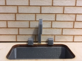
- What processes will be used? - 3D printing (light and sink fixtures) and laser cutting (furniture and house structure); 2D and 3D design, electronic milling and pcb board making
- What questions need to be answered? -
a. What do I need for the electronic portion?
b. What does that pcb look like?
c. How much power do I need? d. Where can I hide the battery and be sure that it is safe for children. - How will it be evaluated? How will I know if my project is successful? I need to give it to a child (5-8 years old) and see how long the playing lasts.
Doll House Electronics
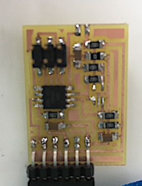
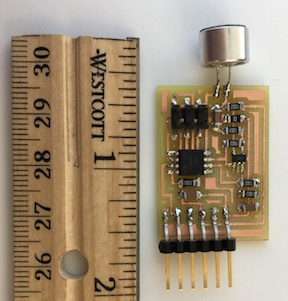
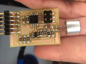
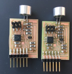
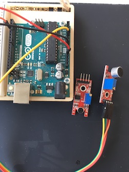
I made a board with a microphone and amplifier to capture the clap sound.
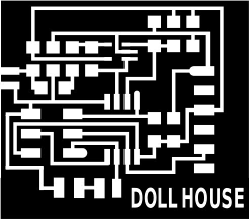
I used the board suggested by Neil here
I changed the file just a little to make the traces bigger. I milled the board on the Roland SRM-20.

and pre-tinned the board:
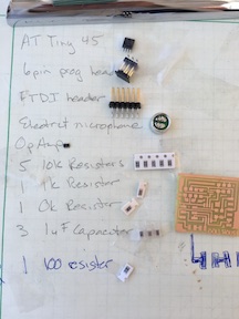
Here’s my list of parts: ATTiny 45 6 pin header FTDI headers Electret microphone OpAmp 5 10K resistors 1 1K resistor 1 0K resistor 3 1uF capacitors
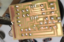
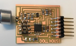
Here’s the board in progress:
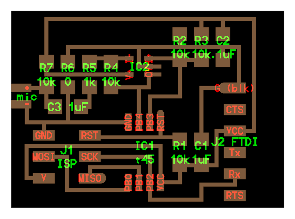
Here’s the schematic that I used to check my connections.
Then I programmed it using my new Parallels on my MacBookPro fresh from the repair people with a new logic board. Parallels wasn’t the easiest thing to learn but the terminal is much like the mac. I had to load all sorts of things that used to be on my mac like the arduino development software and pyserial and tkinter. It look me about 5 hours to get everything installed where it is supposed to be.
I created a file folder for the hello.mic.45 make file, c file and python file and gave the commands:
sudo make -f hello.mic.45.make
It made the hex file! Thanks!

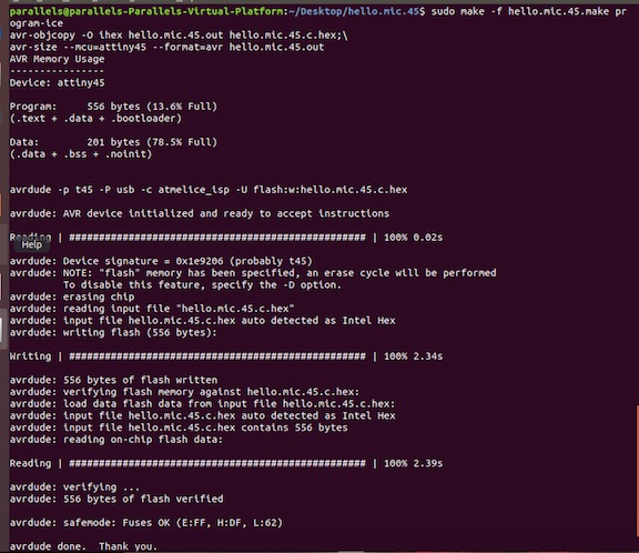
Then sudo make -f hello.mic.45 make program-ice
and it flashed correctly:
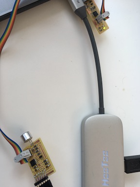
To discover where my board was plugged into my Mac, I asked Terminal to list the usb ports. (lsusb) Then I plugged in the FTDI cable with my board attached and asked lsusb again. The difference was ttyUSB0.
Then I pushed a clap program (written in C) to make the board respond to a clap sound.
Look! Now I can program it with my FAB-programmer!
Now, when the board hears the clap sound, the fireplace will turn on.
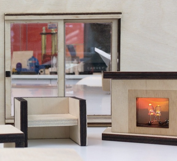
After looking at the picture just above, I rethought the fireplace. I wanted to use some acrylic in the house and I wanted to make the flame look more flame-like (and less like two LEDs) so I made a frosted flame fire-guard for the fireplace. It’s a perfect pressfit and it looks great!!

To connect all of the sconce lights and the fireplace, I needed a “fusebox”. First I tested my idea of hooking up the lights in serial.
With Stephan’s help, we made a fusebox plan. We figured we will need two resistors because the house will run on a 9v battery. The 3 tiny LED sconce lights in a series will need a 100 ohm resistor and the fireplace (with its two larger LEDs) will need a 500 ohm.
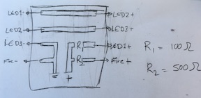
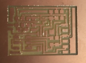
I drew the fusebox plan with Inkscape because it wasn’t very complex. I exported the png at 1000 dps and modded the interior (traces) and exterior files.
Then I milled the fusebox board in the Roland SRM-20.
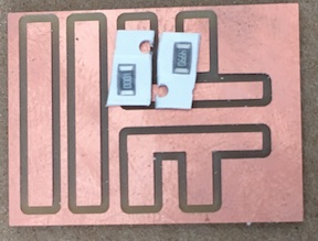
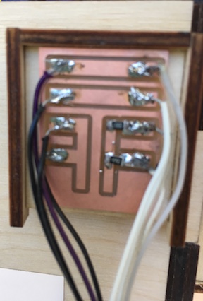
I soldered the two resistors and all of the wires from the 3 sconce lights and the fireplace. Along the way, I made a fusebox box for it to sit in and temporarily, I connected it to the dollhouse with velcro.
Smart Doll House files
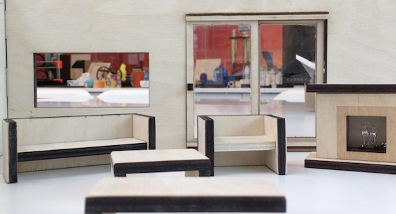
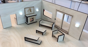
I used a press-fit design for kitchen and livingroom walls. I have built most of the living room furniture and I included a sliding-glass-door in the living room. The living room has a picture window to the outside and a door to the kitchen. All the doors and the windows leave only one piece of wall space for the fireplace. (I had to take the planned pass-through to the kitchen out of the plan to make room for the fireplace.) I will be able to incorporate wall sconces in the living room to light up the house as part of the clap-on-clap-off design. The fireplace will also go on.

Livingroom files
Kitchen files
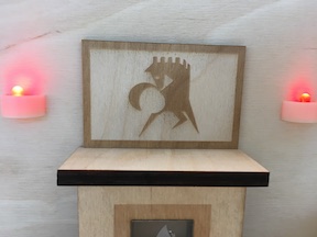
This house has art in the living room and bright red sconces! (I changed these lights to white later.)
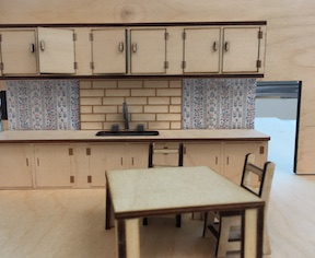
In fact, this house has everything including the kitchen sink!
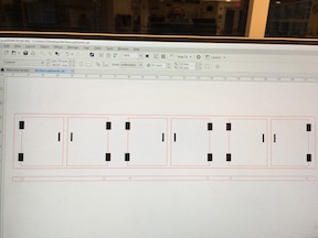
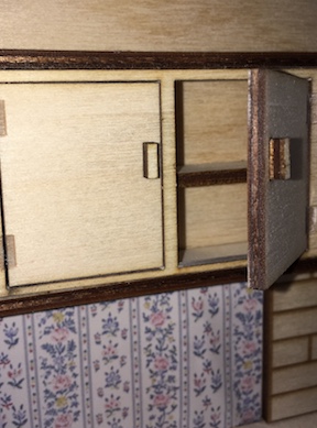
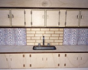
I refined the kitchen with wallpaper and made a cupboard for above the sink with doors that open. I made a jig so that the holes are exactly where they should be.
The kitchen looks really nice!
I put the trellis in the back of the house to cover the sconce lighting wiring.

I put wall paper in the kitchen for the same purpose. I designed and built some furniture for the kitchen to make it a bit more 3D. I have a refrigerator half done but it’s not important. I only set out to build one room (the living room) with the clap on/clap off device.
For all intents and purposes, my project is complete ahead of schedule.
Except for the clap-on/clap-off board.
The Clap-On Board
After my first clap-board was destroyed in the Great Student Ruckas, I remilled and rebuilt the board two weeks ago. It went through the flashing process nicely using Parallels on my MacBook but it never detected sound. The python image was erratic…like it was hearing gibberish. After many re-look at all of the soldering, re-check all of the trace connections, re-flash the board process and working closely with the engineer who works with me, all to no avail, I re-built the board yesterday.
Remilled
 and re-stuffed
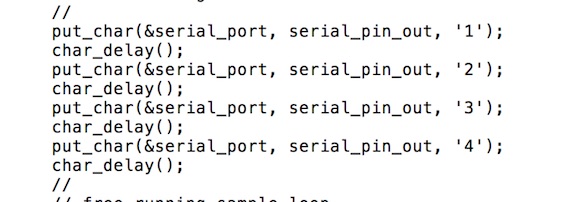
But the third board acted just like the second one. I changed Neil’s c code for the hello.mic board by putting single quotation marks around the 1, 2, 3 and 4 so that when the code runs, it spits out those exact numbers.
Using Arduino’s Sound Monitor, I videotaped the gibberish that the board was spewing. You can see one of the videos here.
You can see that it says 1234 but it is also “detecting” something that is not there. The prognosis looks grim.

So I got out some old Sparkfun sound boards and tried them but, as fate will have it, they would not detect sound either.
I also tried just using a breadboard with a new mic following the directions I found on youtube. It didn’t work either.
I’m wondering if I got a batch of bad microphones....hmmmm. So I ordered some new ones. The sparkfun boards must be old and battered so I ordered a new one of those, too.
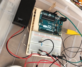
Conversations about the wiring
Blair told me that I would need a MOSFET to run all of my lights. I did some reading about that. When the first board was working (detecting the clap and turning on the circuit) I just had the 3.3v running through the Arduino and a bread board. It wasn’t complicated wiring (and sorry I am I do not have a picture of that) so, I thought I could add some voltage (like use a 9v battery) and hook up all of the lights (two in the fireplace and 3 in a series in the sconces) through the fusebox. Blair seems to think that won’t work. If I ever get a working board, we’ll see.
A Light Goes On
Stephan and I walked through the process of deconstructing the mic board with Blair during a video conference and we (well, Stephan saw it) discovered the problem with all of the boards: There was a little trace of copper connecting the place where the mic is connected to the board. This was causing the mic to short out and that’s why both of the boards acted exactly the same way. Once that piece of copper was removed, the mic operated properly.
And yet another board
I was going to just solder some connections onto the hello.mic.45 board but Blair talked me out of it. I used that board’s design and added the pads I need to connect the PB1 pin to the doll house fireplace. It looks like this:
One new trace goes to the PB1 pin and the other is connected to J1 6 pin’s ground pad.
And yet another board
Decided that a resistor was required and “Doll House” didn’t mill so well, so I re-designed and milled the board again to these specifications:
This one looks better! Added one 100 ohm resistor to my inventory. These are the last mic and amp I have so this has got to be the last board. (Oh, please!)
Also needed to understand more about the amp pins so we could measure voltage in and out. Needed this to do that:

The board looks very nice.
It’s gratifying that I can draw it, mill it, stuff it and put it to work well enough that I can teach the process to someone else. That has always been my goal. It’s also wonderful that flashing the tiny45 microcontroller is simple on my MacBook with Parallels. Now that we can automate the process, we can integrate it into our curriculum.
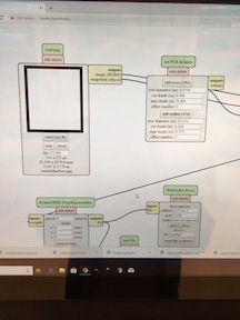
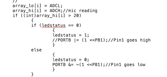
The Code
Now the mic needs to recognize a loud noise and turn on the power to the fireplace. Instead of working with some code I have, we decided to use Neil’s hello.mic c code and just add the command. We chose the PB1 pin on the tiny45 because it’s not been assigned to any other task and it is in a good location on the board to connect to something else. With this bit of code we tell it to switch to HIGH when it gets a message from the mic.
Using the multimeter, we change the code and check the pin over and over. It gets stuck between 2 and 3 and doesn’t seem to be paying attention to anything inbetween.
In the meantime, Blair pointed out that my dollhouse needs better “packaging”. By that he means that I shouldn’t have wires hanging out even though they are in the back of the house.
Last night I found Ivan’s clapclap code here He took Neil’s code for the SPU0414HR5H-SB microphone and changed it to detect a clap so I was able to take Ivan’s code and change it for the Electrek mic and my board listening for output to PB1.
5 Volts is not 5 Volts
I need to be able to run the board independently of the FTDI cable. .. or any cable. My Doll House board likes the Arduino’s 5 volts but that means running it through the Arduino…difficult to hide in the Doll House.
I tried a battery pack - the kind you use to charge your phone when you can’t plug it into an outlet - but it didn’t put out enough power.
I also tried 3 AA batteries (for a total of 5.5 volts) but the board did not recognize it…or 3 AAA batteries.
I also tried using a resistor to get the 9V battery pack down to 5 and even though I could get it to exactly the same 5.1V that the FTDI cable puts out, the board would not recognize it.
So, for now, the fireplace has to be hooked up to my laptop for the clap board to work.
Packaging
My plan is to cover the wires running along the ground with shrubbery and build a drainpipe/conduit to hide the wires running up the wall.
See? Cannot see those wires behind the shrubbery. Thank goodness for our architecture department and their little shrubs!

Here’s the conduit that covers the wires and the fusebox where the wiring comes together. The fusebox cover stays on with tiny magnets. The 9v battery is hidden in the windowbox. It could be someplace to put flowers or an outdoor counter for dining.
Bill of Materials - What is made; What is purchased
My intent was to make the Electronic Doll House out of exclusively “left over” materials so that the cost would be negligible.
- Approximately 2 sq. feet of 6mm plywood (walls and furniture)
- Approximately 1 sq. foot of 3mm plywood (kitchen built-ins and furniture, trellis)
- Approximately 4 sq. inches of clear plexi (sliding glass doors and fireplace)
- Approximately 6 sq. inches of sticky-back paper for printer/vinyl cutter (vines and wallpaper)
- A small amount of 3D printer filament (kitchen sink, faucets, knobs, light fixtures)
- 5 LED lights (about $.06 each)
- 1 9V battery (about $1.00)
- 1 9V battery pack with on/off switch ($3.25 each) (That’s the big-ticket item)
- There is also a circuit board to be made for the clap on device, the fuse box board to make (so copper plated pcb board is required) and misc. wires to connect the lights to the battery
Originally, the design was for just one room - just the living room - but I was having so much fun making the house that I decided to make the kitchen, too.
The original design had separate battery power for each light but it evolved into an old-fashioned “fuse box”. All of the lighting wires went through the walls, to the back of the house (patio area) and up into a fusebox designed like a circuit board.
Final Project Links
Link to my Final Project Slide
Link to my Final Project Video
Project Thoughts
I think that it is a great idea to help others make toys for very little money. Toys and play are crucial for emotional and cognitive development. This toy has lights that go on and off electronically but, other than that, it is a typical doll house that is perfect for story making and telling.