11. Input devices
Assignment
assignment individual assignment:
~~measure something: add a sensor to a microcontroller board that you have designed and read it~~
group assignment:
~~probe an input device’s analog levels and digital signals~~
Group Assignment
We investigated the digital signal of the LED on a blinky board with the oscilloscope. We attached the probe ground to the ground pin on the FTDI on the board. We used the probe to touch the positive end of the LED (the other side, ground, produces no signal). We could see the width of square wave corresponded to the frequency of the LED blinking. This means that a slower blink produced a wider line wave and faster blinking produced small line waves.
To test an analog signal, we connected to a potentiometer which has a spectrum, rather than just on/off like the LED. The o’scope read a frequency change when the potentiometer dial was moved. You can see in the video that when the potentiometer is turned up so that the screen can be seen, the signature registers a higher voltage. The higher the voltage, the more contrast there is in the screen – the letters are brighter. The contrast on the screen can be improved by minor potentiometer changes which result in different voltage. Beyond a threshold voltage, the screen goes dark.
My Research on Input devices
Input devices seems fairly obvious–buttons and switches and input by sound and light. There’s a button on one of my boards and the user inputs to the board by pushing on the button. It should create a response such as lighting the LED.
Input devices can be used to sense the environment around us. Our purpose this week is to create a board that can sense different input using sensors and respond with an action based on the input.
A common example is a light sensor. A Light Dependent Resistor (LDR)is a component that changes depending on the intensity of light around it. An LDR would be a good project. I could create a board that turn on an LED when it’s dark…an auto night light.
Here are some other examples of input devices:
- temperature sensor
- white light sensor
- touch sensor
- magnetic sensor
- greyscale sensor (because things aren’t always black and white?)
- vibration sensor
- tilt sensor
- sound sensor
A Board with A Button
At the top of Neil’s list of input devices is a button. Neil’s board uses an ATtiny 45, but I designed my board around the ATtiny44 architecture. This, I thought, would give me more options for adding other things to the board.
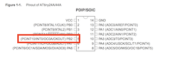
I investigated the tiny44 by reading through its datasheet.. I needed, especially, to understand the pins and the ports. I will be connecting an LED and a button to my board so I need to know how they should be connected to the tiny44. This schematic shows me where VCC and GND are, as well as which pins I can use for input and for output. I’ll be connecting my LED to pin PB2.
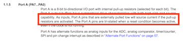
I know from reading Neil’s code that I will need to use PORTA and PORTB, as well. The datasheet says that PortA pins that are externally pulled low will source current if the pull-up resistors are activated. This means that current will flow through (and light the LED in both the up and down button state) through the software.
I started with the parts for the schematic of the hello.echo board and added, a button, a 499 resistor and a red LED.
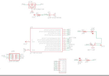
I know I need a “pull up resistor” for the button. A pull-up resistor connects unused input pins to the dc supply voltage (VCC) to keep the given input HIGH. In schematic view, it looks like this:
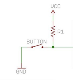
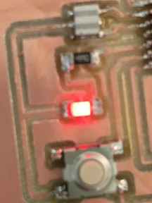
In this case, the LED should flash (slowly) so long as the board is connected to power.
And I know that I need a 499ohm resistor for a red LED. Even if I didn’t know that, I could calculate the value of the resistor by hand using Ohms law, or just use this calculator.
Everything looked pretty straightforward in the schematic, even when I added another LED and resistor.
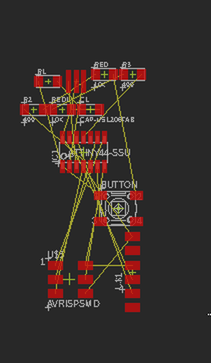
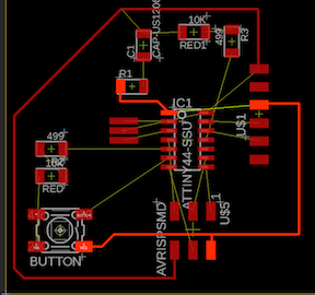
When I moved into the board view, though, things got a little trickier.
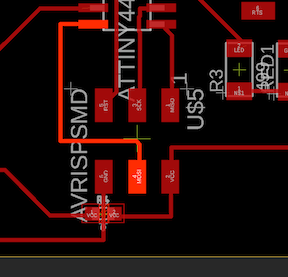
This is the original mess.
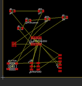
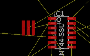
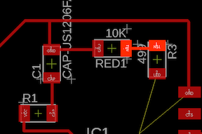
I separated everything so I could look at where the components need connecting.
This closeup made it more clear where the capacitor, resistors and the buttonLED needed to go — close to that crystal.
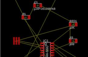
The crystal likes to snuggle up with the tiny44. It’s connected at two pins: PB1 and PB0. That’s a good way to know where to place it.
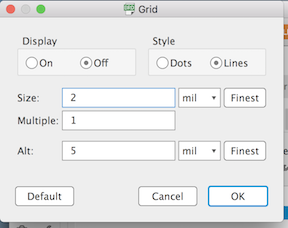
I never remember to change my grid setting (from 50 to 2) until I’m having trouble moving parts close to each other. For a smoother way of moving, make the Grid size very small.
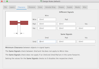
And while I think of it, I make sure that my clearance numbers are all 16. This will help me ensure that my traces are not too close to each other or to any pads.
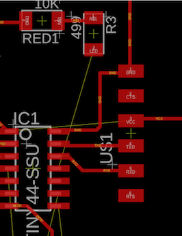
It took me 10 minutes of moving things around to get to here. Connections look pretty clear cut. I’ve drawn a global GND trace.
Then I drew a global VCC trace.
And then I drew some of the easy connections. No obstructions.
I ran into a problem with at the 6 pin. I cannot run the VCC out to the button because that’s where my global GND trace goes. I spent about an hour redrawing traces to try to work in that VCC trace. I finally remembered something my co-worker taught me about using a 0 ohm resistor as a bridge.
I went back to the schematic view, get a 0 resistor, and connect both sides to VCC.
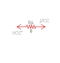
Now when I go back to the board view, I can place this resistor over the GND trace to connect the button to VCC.
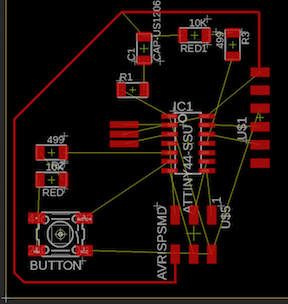
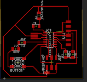
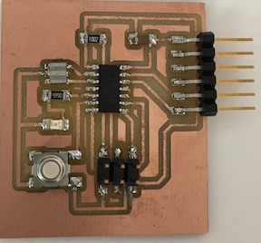
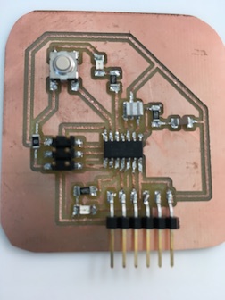
My board (version1) looks pretty good!
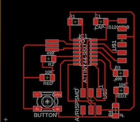
Version 2 (with an extra LED/resistor set) looks good, too!
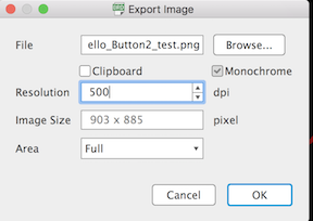
I turn off all of the layers except for the Top and File—>Export—>Image
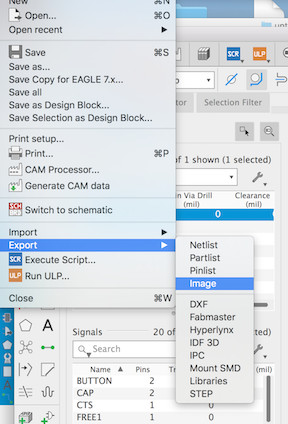
I give my file a name and destination (always my Desktop), check monochrome, resolution 500 full area and I take note of the image size. I know it’s too big. It has to be fixed in Inkscape.
I go back and hide the top layer but display the Dimensions. Then I export this file, as well. It will be my “interior” file.
Inkscape –> Milling –> Soldering
I have to reduce the size of the boards to 52% in Inkscape to make them come out the right size. Then I can export them in 1000 dpi, “mod” them to produce the .rml files, and mill them on the Roland SRM-20.
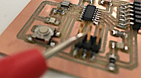
I pre-tin and solder the components one at a time, checking the connections from the top of the component. By that I mean that checking a connection from the solder point just tells you that the trace is good. To ensure your soldered connections are holding, you have to put the multimeter probe on the component, not on the solder. In the picture below, I’m holding the probe to the upper pin of the 6 pin male connector.
This is especially tricky with buttons.
Buttons
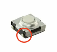
In this side picture, you see small connection points on the sides of the button casing. But we don’t have to connect that point with solder to the board.
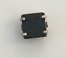
In this bottom picture, you can see the small connection points on the bottom of the button casing. This is where the button needs to be attached to the board.
LEDs
What I have to remember about LEDs is that the anode side points toward the resistor. I can tell which is anode and which is cathode because the LED will light up if the multimeter’s red probe is on the anode and black is on the cathode.
Some LEDs have a green line on one side that designates the cathode, so they I only have to remember to point the green line away from the resistor.
Crystal
The crystal needs soldering in three lines underneath it. I lay out the solder on the pads beyond the size of the crystal. I lay the crystal on top of the 3 lines and push down on the crystal with my tweezers as I heat up and melt the solder underneath each of the 3 sections of the crystal. This is one of those parts you want to check a few times to make sure your connections are solid.
My Research about C
I have spent a lot of time looking at and researching about Neil’s code for various boards. The code for my board, it seems, can be much more simple. I have to #include a few things:
I need to define where my button pin is connected to the microcontroller
#define button_in PA2
and where the LED is connected
#define led_pin PB2
I want my button to blink at two speeds so I need to designate an amount of time delay between the blinks. A small amount of time for fast blinking and a larger amount of time for slow blinking.
In the “main” part of the code, I need to set the Data Director Register for port B (DDRB) for my LED and set the PORTB – Port B Data Register - for the button. You can read about ATTiny port manipulation here.
Last, I need a “while” for showing the difference between button-pushed and button-not-pushed.
It doesn’t seem like it should take very much code.
First Code
It is a good idea to start as simply as possible, so I wrote this just to see if it would work:
   #include <avr/io.h>           // AVR device-specific IO definitions

   #define led_pin PB2           // pin where LED is connected

int main(void)

{
  DDRB |= (1 << led_pin);     // set LED pin as output
  PORTB |= (1 << led_pin);    // turn LED on
}
I modified a standard makefile for this firstcode.c
PROJECT=firstcode
SOURCES=$(PROJECT).c
MMCU=attiny44
F_CPU = 20000000

CFLAGS=-mmcu=$(MMCU) -Wall -Os -DF_CPU=$(F_CPU)

$(PROJECT).hex: $(PROJECT).out
   avr-objcopy -O ihex $(PROJECT).out $(PROJECT).c.hex;\
   avr-size --mcu=$(MMCU) --format=avr $(PROJECT).out

$(PROJECT).out: $(SOURCES)
   avr-gcc $(CFLAGS) -I./ -o $(PROJECT).out $(SOURCES)

program-bsd: $(PROJECT).hex
   avrdude -p t44 -c bsd -U flash:w:$(PROJECT).c.hex

program-dasa: $(PROJECT).hex
   avrdude -p t44 -P /dev/ttyUSB0 -c dasa -U flash:w:$(PROJECT).c.hex

program-ice: $(PROJECT).hex
   avrdude -p t44 -P usb -c atmelice_isp -U flash:w:$(PROJECT).c.hex
This created the hex and out files with the command sudo make -f firstcode.c.make
Then I pushed it to the board with sudo make -f firstcode.c.make program-ice
LED turned on!!
Second Code
To allow the tiny44 to see and use the button, I wrote:
#define button_pin PA2
To define the terms I will use later in the code, I wrote:
#define fast_blink 20
#define slow_blink 60
My code is super simple. It looks like this:
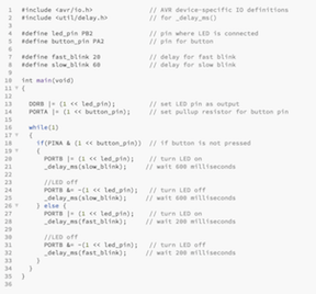
I pushed it to the tiny44 as before and it does what I asked of it: blink a two different speeds depending upon the button push.
I spent some time tinkering with the code, changing the speed of the blinking and changing the wait time between blinks.
zipfile of .brd .sch .c traces and outline
Versions of this board
I made this board twice with slightly different layouts and adding another LED. I’m going to use this board later so I did quite a bit of experimenting with it.
Thoughts about this project
I spent some time with this project really thinking about board design and code. I tinkered with the code, speeding up and slowing down the blinking, changing the wait time between blinks. I learned some C code during this project and more about using the button as an input device. I also learned about the vast array of AVR libraries and library modules, although I probably do not have the nomenclature correct yet.