12. Output devices
Assignment
individual assignment:
~~add an output device to a microcontroller board you’ve designed and program it to do something~~
group assignment:
~~measure the power consumption of an output device~~
Research on Output
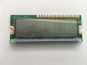
This week’s assignment is about output devices. An output device is a microcontroller that enables an output pin to activate a device. Examples are LEDs, LCDs, motor drivers, etc. What I would like to do is connect to this LCD module. It is 16x2 characters.
LCD stands for Liquid Crystal Display. On this one, from left to right, the first pin is the Ground pin. The second pin is the VCC which is connected to the 5 volts pin. Next is the Vo pin which can be attached to a potentiometer for controlling the contrast of the display.
Next, The RS pin (register select pin) is used to send commands or data to the LCD. If the RS pin is set on low state or zero volts, then commands can be sent to the LCD. Sample commands are: set the cursor to a specific location, clear the display, turn off the display and so on. When the RS pin is set on high state (5 volts) data or characters can be sent to the LCD.
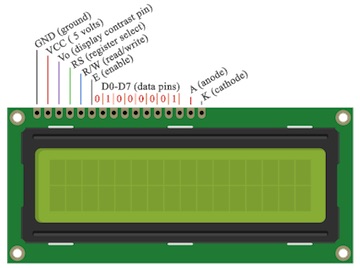
The Read/Write pin selects read or write to the LCD. The write mode is used for writing or sending commands and data to the LCD. The read mode is used by the LCD itself when executing the program.
The E pin enables writing to the registers (the next 8 data pins from D0 to D7). The 8 bits of data are written to the registers according to the ASCII table. For example if we want the LCD to display an uppercase A, we send 0100 0001 to the registers. Each pin gets a 0 or a 1.
The last two pins are A and K. They are the anode and cathode for the LCD back light.
# Group Assignment - measure the power consumption of an output device
In order to better understand my LCD, I looked at its datasheet. It says that GND is pin1, it is looking for a 5V power supply on pin2 (it can take 4.7V to 5.3V), a potentiometer can be connected to pin3; pin4 is looking for data/instruction input. For this project, I’m not using the next 4 pins. The next 6 pins control the screen on the LCD, so I don’t need them right now.
To get ready for this assignment, I watched a video to learn more about using the Fluke multimeter.
To measure the power consumption I can use the multimeter and check the voltage “V” and the current (or amperage) “A”of the device. The LCD is getting 5.2V. I set the current to 1 ampere and connect the LCD (already powered) inside the series. I saw the amperage fluctuate, but settle on .107.
Then we use the power formula:
Power (measured in watts) = voltage (measured in volts) * current (measured in amps)
To find out how much power it consumes, we need to put the multimeter in series with the LCD. Before making this test with my LCD, I set it up on an Arduino first.

with 5V going into the LED+220 resistor and measured in milliamps (.001 of an amp)
Holding the ground lead to the LED side of the resistor and the other to the power.
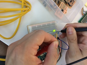
It came out to 13.8 milliamps.
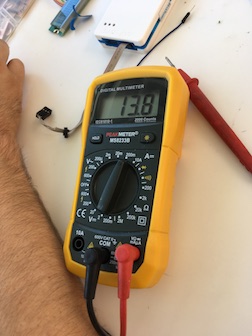
Then I tried it on the LCD. It measured only .107milliamps (.000107 amps).

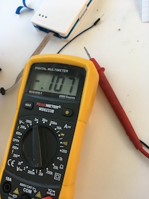
Multiply that by 5.2V (which is what the LCD was getting through the FTDI cable) = 5.5 milliwatts or .0005564 watts.
Individual Assignment Using Arduino
My programmer board isn’t working and I’m behind on all of the subsequent assignments. I’m going to use Arduino for this assignment so I can catch up.
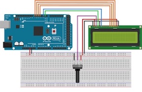
Here is the Fritzing diagram for hooking up the Arduino to the LCD. You can find these diagrams all over the internet so you don’t have to make your own but Fritzing is pretty user-friendly.
Now I have to gather the parts.
Ideally, I should have male-to-male jumpers wires of certain colors like (4) black for ground and (2)red for 5V. I need a lot of these wires of nondistinct colors but I did choose as many orange as I could find to match my Fritzing diagram.
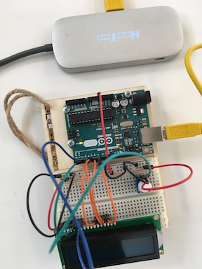
My arduino board is on a platform with the breadboard. I also needed the LCD and a potentiometer. And power cable. And it turned out I needed a USB hub because the Arduino did not want to connect to my MacBook using my standard USB-C translator. It was fine with the hub, though. Go figure.
I connected all of the jumper wires according to the diagram.
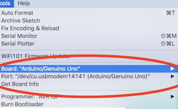
I set my arduino software to recognize my Uno board and the usbhub.
Then I used this LCD program:
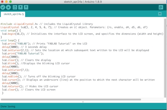
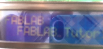
And it came out looking like this. Well, it looked better than this picture in real-life. It says “FABLAB Tutorial”
As an added benefit, now that I understand the various connections of this device, I can create a board in Eagle for an LCD!
In this example, the input comes from my computer and the output comes from the LCDisplay. I can see some practical uses for this in our Lab such as making announcements about upcoming events/classes.
Individual Assignment without Arduino
Neil’s LCD Board
As a safety net, I started this project with Neil’s LCD Board. This way, if it doesn’t work I’ll be able to tell that problems stem from the LCD. I downloaded the files for traces and interior along with his c code and make file from this week’s website.
I modded and milled the board in the Roland SRM-20 and soldered on the components.
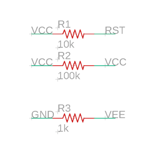
As always, I started the soldering with the microprocessor (ATTiny44 in this case). Then I put on the IC2-5V that regulates the voltage that the board gets from the 2x2 pin (via the Bridge Board from Networking week). Then the resonator and its resistor 10k. Then the two other resistors 100k and 1k. Then I put on the 2x2 pin, then the 2x3 AVRISP pin and last is the 2x5 pine. As I solder on each component, I check the connections with the multimeter. In a few instrances, I discovered that the component looked like it was soldered securely but it was not.
LCD
I have the Lumex 1602 in my inventory so I downloaded the data sheet. There’s important information there about what pins do what. In this case, it was very important to look at this datasheet because the pin layout isn’t much like the order in which the pins we need lay (and it is different from the LCD I used with Arduino).
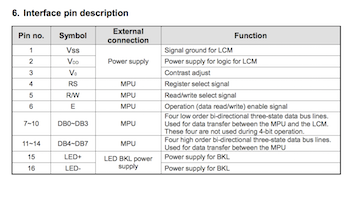
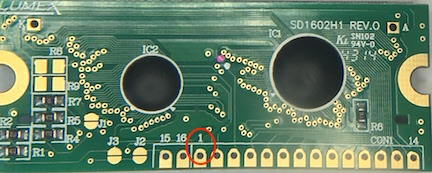
I got a piece of 10 strand wire and soldered the strands on from right to left starting with GND in pin1, then VCC in pin2, Vee in pin3, then RS, R/W and E in pins 4, 5 and 6 respectively. You can see in the interface pin description that E is for Enable, R/W is Read/Write, and RS is for Register Select Signal. This lets the user select “instruction mode” or “character mode” of a LCD. In our case, we are sending characters to the LCD.
I stuck the wires through from the front and soldered them gently on the back.
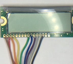
You can see that I didn’t use DB1 - DB4 in accordance with Neil’s diagram and his c code. I left those holes empty and soldered the next 4 wires (yellow, orange, red and brown) into DB4 - DB7 holes.
Code
I used Neil’s c code but made one change to it. Where he has “Hello to” on one line and “the world” on the next, “I wrote Hello from” and “Guerin”…the name of our Lab.
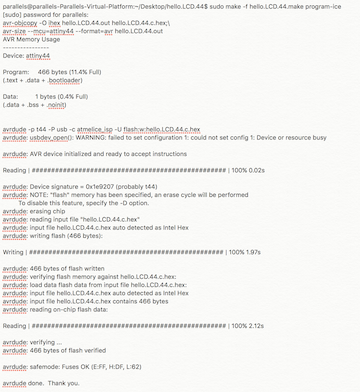
I used the make file to create the .hex and .out files and then flashed the code onto the tiny44. As you can see, it did that beautifully!
Video
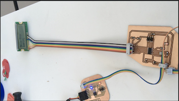
In this video the LCD board is connected to power via its 2x2 pin from a Bridge Board that has an FTDI cable connection. The LCD Board sends the power on to the LCD which lights up and gives its message.
My Own Board
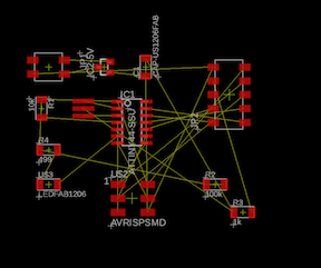
Designing on Eagle
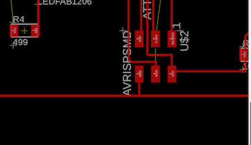
To begin making my own LCD board, I went to Eagle and gathered all of the components I need.
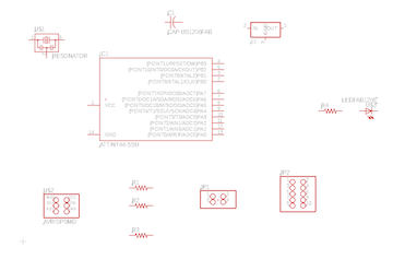
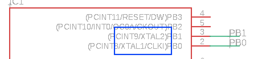
Then I connected the components by naming the connections. I started with the resonator XTAL by connecting it to PB1 and PB0.
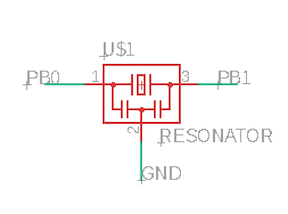
You can see that they should be connected there because the ATtiny44 tells us that this is a good connection in its description.
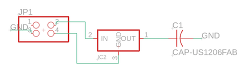
I know that my 2x2 pin (where the power is routed through) must be in line with the 5v regulator so I put them in a line with the capacitor. In this case I actually drew the connections instead of naming them.
I can set up the connections on the 2x5 pin where the LCD connects exactly as they were on my earlier board.

I labeled the connections for the resistors.
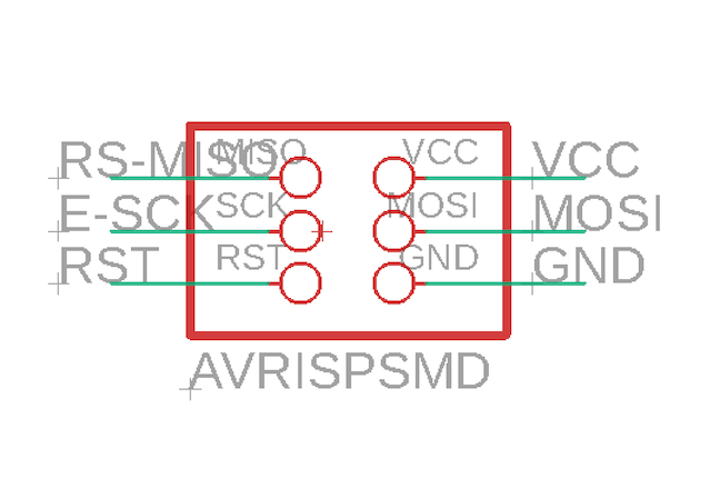
I have had some mix-ups with connections when the labels are not clear so this time I named MISO “RS-MISO” so that I understand and remember the pin connections better later on.
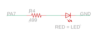
Then I add my LED and its resistor to pin PA7. I know that pin is a good connection for the LED (and the resistor is correct) from an earlier board I built.
The schematic is ready.
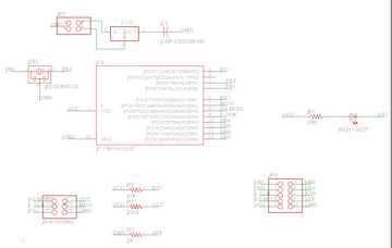
When I go to the BRD view, I know that the tiny44 needs to go in the middle for the most efficient set up. The 2x3 pin should go below and slightly to the right of the tiny44. The resonator always goes to the left and at the top of the tiny44 becasue it is connected to PB0 and PB1.
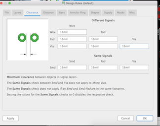
Before routing any traces, I set my Design Rules clearance to 16mm.
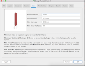
And my trace size to 12mm.
I locate the LED and its resistor over by PA7 on the bottom left side of the tiny44. This might be a problem because it needs VCC.
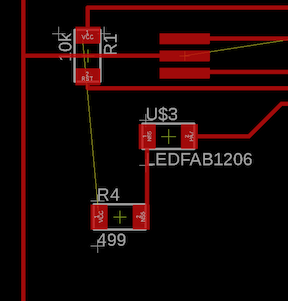
I solve the problem by using a 0 ohm resistor to jump over another trace. Then I can connect to VCC at the 2x3 pin. I go back into the schematic view, add another resistor and connect both sides to VCC.
Now my BRD is complete. I drew all of the traces by hand instead of asking Autoroute for help.
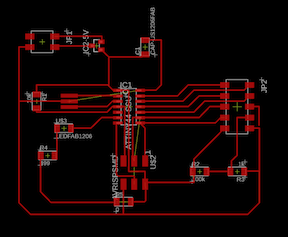
I can see that this is going to be a very large board (over 2” x 2”) but that’s good. There will be lots of pin connections and I want to give the female connectors and the wires a lot of room.
Steps from Eagle to Board
I downloaded the top layer as monochrome at 500 dpi and put it into Inkscape. There I shrink it to 52% and then fix some of the traces. Because of the way I named my connections, there are a few connections that Eagle would not let me make (such as connecting R/W to GND), so I fixed these by drawing the traces manually.
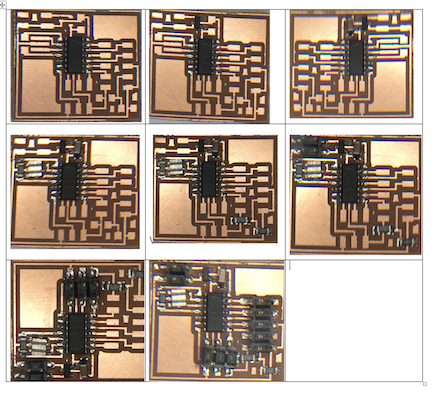
I transferred the board png file to the milling computer, put it through mods, and milled it. The mill did a good job except where the trace had to go through the middle of the 5V regulator. I had to clear that trace with an exacto blade.
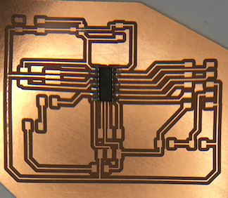
I soldered on the components exactly as I did Neil’s board starting with the tiny44 and ending with the 2x5 pin. As I solder on each component, I check the connections with the multimeter.
Then I flashed it with the same code as above and it worked beautifully!
Change the code to add the LED
To have the LED come on, I need to include a few lines of code. In the define part, I add
#define led_pin PA7
#define LED_ON (1<<led_pin)
PORTA = lcdbyte | LED_ON;
It works!