5. Electronics production
Group assignment—~~Characterize the design rules for your PCB production process~~
Individual assignment— ~~Make an in-circuit programmer by milling the PCB, program it, then optionally, trying other processes.~~
Learning outcomes
- ~~Describe the process of milling, stuffing, de-bugging and programming~~
- ~~Demonstrate correct workflows and identify areas for improvement if required~~
Have you?
- ~~Shown how you made and programmed the board~~
- ~~Explained any problems and how you fixed them~~
- ~~Included a ‘hero shot’ of your board~~
This week I was supposed to characterize the specifications of our PCB production process and make an in-circuit programmer by milling the PCB. Because my end mills did not arrive (inspite of paying for 2-day air) I tried using a small CNC router instead. I plan to demonstrate that I can describe the process of milling, soldering, de-bugging and programming by documenting it all here. I always demonstrate correct workflows and identify areas for improvement…lots of areas for improvement.
Research
Our Lab has the standard Roland SRM-20.

I researched its prior use by asking people who have worked here for the past 3 years. They all told me that the prior manager of this Lab and a student tried and tried to get the machine to work but never could. That was a scary beginning to this project! If an engineer and a top student couldn’t get the machine to mill a circuit, how will I ever be able to do it?
Undaunted, I looked around to see if we have what is needed to make the Roland mill work. We have the copper plates and all of the electronic elements here but I could not find any End Mills except the one that is in the machine. I immediately ordered the three that we were told we would need for “overnight delivery”, but this is 2 days later and I still don’t have them.
I found the Roland SRM-20 manual online (on the Roland website) and read it. (Links are below.) I gained a preliminary understanding of what software is needed. Inkscape was already loaded on the computer. We just needed to load the Roland software. Roland has a 3D building software (which we loaded) but once I found out that Inkscape would work and Mods was recommended, I abandoned the idea of learning yet another piece of software.
I found the circuit board png on the Fab Academy website and imported it into Inkscape. I clicked on “Print” in Inkscape and the mill started milling! Quick! Turn off the machine!
The Roland monoFab SRM-20 cnc milling machine will also mill modeling wax, chemical wood, foam, acrylic, ABS and other materials. Workpiece table size is 232.2mm wide x 156.6mm deep. Distance From collet tip to the table is a maximum of 130.75mm You can find the specifications here
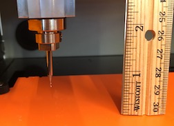
I needed to know how much of a sacrificial layer I needed so I used a measuring utensil.
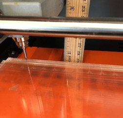
Then I cut three pieces of 3mm acrylic, stacked them up, and measured again.
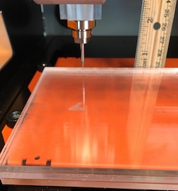
Oops! Need another piece of acrylic.
I learned how to use the VPanel. Zero-ing on X and Y was easy.
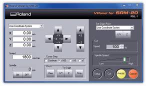
It took a bit more figuring to zero on the Z axis. The key is dropping the end mill as close to the cutting surface as possible, being careful not to gouge it with the sharp end. Then loosen the endmill with the allen wrench and let it drop by itself to the surface. Now it is at true zero. Tighten it in the chuck with the allen wrench and lift it with the up arrow in VPanel.
I think I set up the acrylic so that I don’t need another one for the .010” diameter end mill but I’ll wait until the end mills arrive. Fingers crossed they will be here tomorrow so I can spend Sunday and Monday learning how to use them.
----Time Lapse----
Carvey Machine
Here it is Tuesday and my end mills haven’t arrived. I have been busy, though.
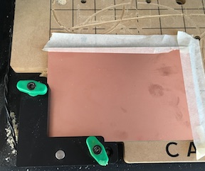
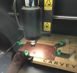
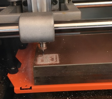
I tried to mill the PCB on my Carvey Machine but I was unsuccessful. Here is the board clamped into place in my CNC router.
But, even though I slowed down the decent of the bit, I broke it as soon as it touched the copper.
I slowed everything down and tried again. The Carvey has a PCB setting so I thought I’d be fine, even though I have not had much success with the 1/32 bit…even on soft wood.
But it didn’t work.
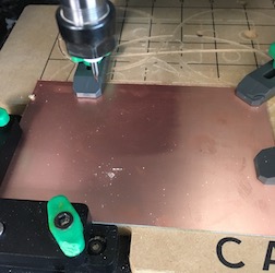
End of this story: The 1/32 bit broke (two of them) regardless of the settings I tried.
The larger bit probably could have cut through the copper, but I would have had to make the board really big to get the detail required.
I’ll have to wait for the Roland end mills.
Roland SRM-20
In preparation for receiving the end mills, I got the Roland SRM-20 ready. Over the last week, I
- accessed Mods on-line (http://mods.cba.mit.edu) and
- used a past student’s instructions to learn to use Mods [http://fabacademy.org/2018/labs/fablabisafjorour/students/joannes-djurhuus/img/week7/Mill%20a%20PCB%20using%20mods.pdf] It was super helpful! Clear and step-by-step.
- followed the steps and was able to download the first rml file
- for the second file (to cut out around the first file’s shape) I needed to click on “mill outline” in the “Set PCB” panel
- figured out how to use vPanel to zero the Roland SRM Desktop Mill on the X, Y and Z axis
- built a multi-layer plexiglass sacrificial base by gluing 7 x 5” layers of clear plexi together
- double-sticky-taped the base to the mill’s base (don’t cover the entire surface with tape or you will never get it off)
- double-sticky-taped the copper-plated board (6 x 4) to the sacrificial base
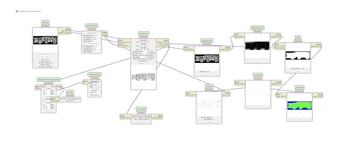
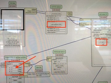
The mods program looks like this:
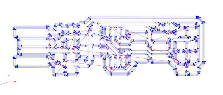
When the board is modded, the cut paths look like this:
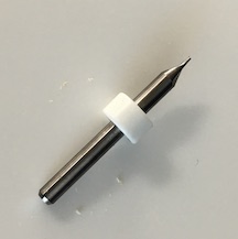
All I need now is the end mills. I’m all set up for 1/64.
----Time Lapse----
The End Mills arrived! Yay!
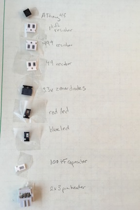
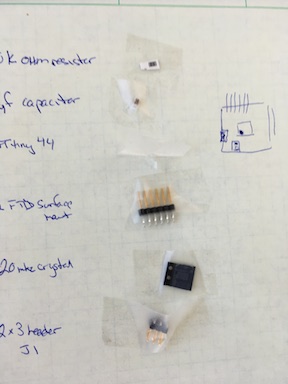
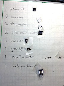
Today I had an opportunity to gather the parts for this tiny circuit board. Taping them to the paper was a good idea. They won’t get lost on my desk!
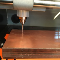
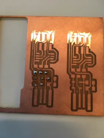
The Roland is not milling evenly across the board so the traces aren’t showing on the right side. We tested the level and found that the sacrificial layer is not level. It could be that the table isn’t level or the floor isn’t level, but it doesn’t seem logical that the table inside the mill isn’t level.

After going through several solutions that involved technology, I ended up putting an extra layer of double sticky tape on the end that wasn’t milling and that solved the problem.
Vinyl Cutter Circuits?
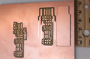
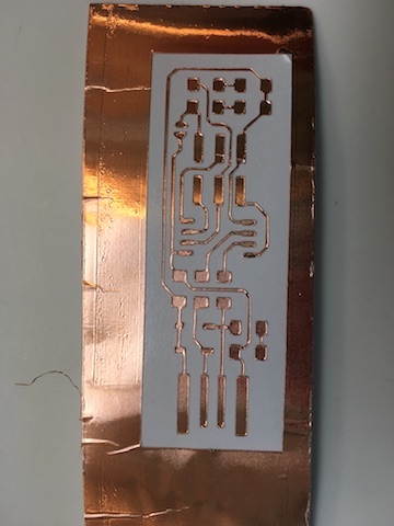
In the meantime, I also tried cutting the pcb traces on the Roland vinyl cutter. I had to experiment with different speed and force settings before I finally got one that worked (3 or 4 failed attempts), but it was too delicate to take the extra out.
Speed (10) Force (30)
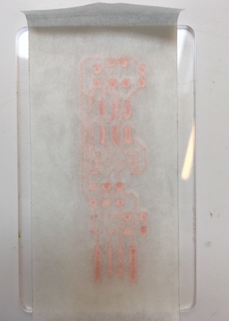
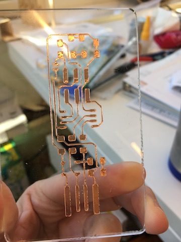
I made a bigger one and put it on a piece of plexi. It looks lovely! But the traces are too big for the electronic parts I have available to me.
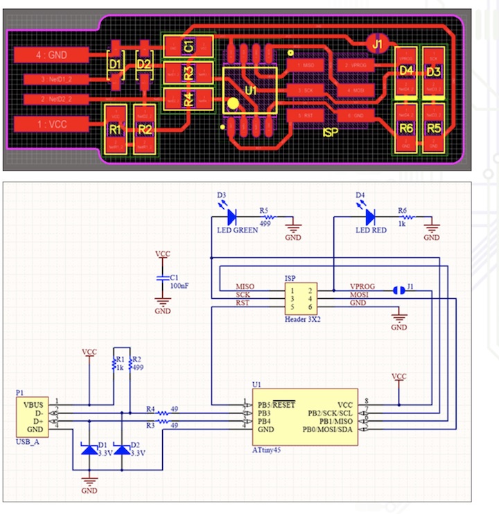
Circuit Schematic
Experimenting with the Roland
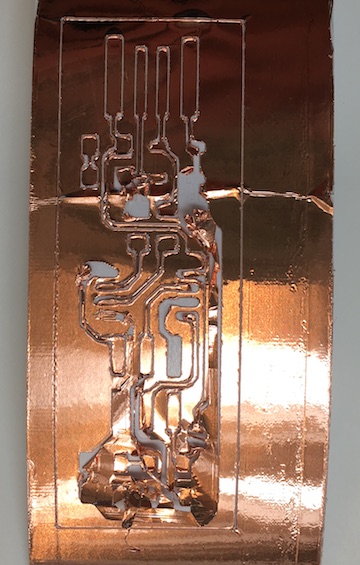
I downloaded the linetest from the website

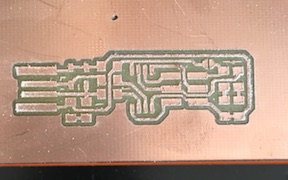
I used mods as described above to set up the line test file for the 1/64 endmill. This is what it looked like after it was finished.
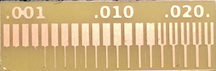
This is a good exercise for students to do before they begin using the Roland mill. It presents hard evidence of how small the trace can be and still be successful.
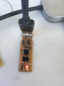
Soldering
Although I have done many different craft styles, I have never learned to solder so I spent some time practicing.
It doesn’t seem that hard so I started soldering the parts onto my board. I have the challenges that my eyesight isn’t 20/20 anymore and my hands shake when I try to hold the tiny parts with tweezers, but I have gotten some of the parts onto the board.
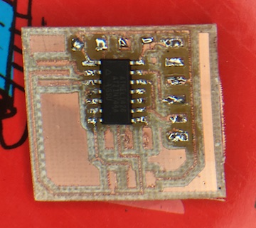
Here you can see that I tinned the traces.
And then soldered on the rest of the parts.
Making the board come alive!
After I (finally) finished soldering the next step was to program the new board. I downloaded and installed CrossPack, downloaded the firmware source code and extracted the zip folder to get a folder named fts_firmware_bdm_v1. Inside that folder there is a called Makefile. You can use any text editor to open and and edit that file, but there was nothing I needed to change.
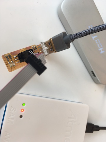
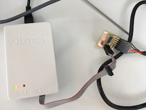
I connected the tiny programmer to my Mac laptop using a USB extension cable and asked my laptop to find it but I got this message:
Spent the day soldering, resoldering, unsoldering and cleaning up the board but no joy. The Atmel red light is on through the USB hub.
Plugging in the 6 pin alone gets me nothing. And plugging in the USB gets me nothing. But plugging them both in gets me the green light on the Atmel.
The LEDs on the board do not respond to any commands.
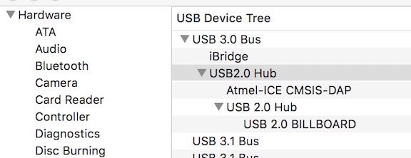
The Macbook’s System Report sees the USB hub and the Atmel but not the board.
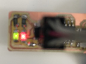
I discovered that I had soldered the LEDs backwards on the board. Fixed that. Now I have the red LED on when the board is plugged into the USB. That means that there is current running through the board from my laptop. Yet “make flash” still gets me the same message–the computer isn’t finding the board.
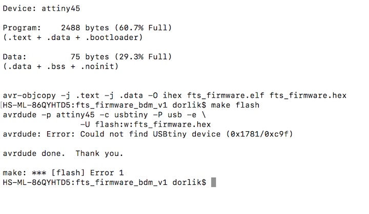
I changed the Makefile so it knows that I have an AtmelICE. Now the computer isn’t finding my USB port. The error message now says:
avrdude -p attiny45 -c avrisp -P usb -e \ -U flash:w:fts_firmware.hex avrdude: ser_open(): can’t open device “usb”: No such file or directory
avrdude done. Thank you.
make: *** [flash] Error 1 HS-ML-86QYHTD5:fts_firmware_bdm_v1 dorlik$
The device tree of my computer still knows I have USB ports so I don’t know what happened with Makefile.
The Ubuntu Challenge
So....switched to Ubuntu computer and tried again with my mentor, Blair. At first, the Ubuntu machine said “can’t open device usb” and I thought I would scream!
Then it said:
vrdude -p attiny45 -c atmelice_isp -P usb -e \ -U flash:w:fts_firmware.hex avrdude: usbdev_open(): WARNING: failed to set configuration 1: could not set config 1: Device or resource busy
avrdude: stk500v2_command(): command failed avrdude: bad response to AVR sign-on command: 0xa0 avrdude: Target prepared for ISP, signed off. avrdude: Now retrying without power-cycling the target. avrdude: stk500v2_command(): command failed avrdude: bad response to AVR sign-on command: 0xa0 avrdude: Target prepared for ISP, signed off. avrdude: Now retrying without power-cycling the target. avrdude: stk500v2_command(): command failed avrdude: bad response to AVR sign-on command: 0xa0 avrdude: Target prepared for ISP, signed off. avrdude: Now retrying without power-cycling the target. avrdude: stk500v2_command(): command failed avrdude: bad response to AVR sign-on command: 0xa0 avrdude: Target prepared for ISP, signed off. avrdude: Now retrying without power-cycling the target. avrdude: stk500v2_command(): command failed avrdude: bad response to AVR sign-on command: 0xa0 avrdude: Failed to return from debugWIRE to ISP. avrdude: initialization failed, rc=-1 Double check connections and try again, or use -F to override this check.
Thinking I may have plugged the 6 pin in backwards (Double check connections and try again), I changed it to be the other way.
Then I got:
avrdude -p attiny45 -c atmelice_isp -P usb -e \ -U flash:w:fts_firmware.hex avrdude: jtag3_edbg_recv(): Unexpected response 0x81, 0x00 avrdude: failed to sync with the JTAGICE3 in ISP mode
avrdude done. Thank you.
Makefile:61: recipe for target ‘flash’ failed make: *** [flash] Error 1
I did some searching for what that means but did not find anything useful.
Back to Mac
I gave up on the Ubuntu machine and went back to my Macbook Pro, only to be doomed to “avrdude: ser_open(): can’t open device “usb”: No such file or directory”.
I looked at what my USB ports are called but it didn’t make any sense. I spent about 4 hours messing around with finding out the name of the ports, etc. The names of the ports are MAL and SOC. That makes no sense for many reasons but one of them is that I have 4 ports! But I relented and changed all of the references to USB to a reference to /dev/MAL. Great! Now “make flash” gets me a different error message!
“Programmer is not responding”. It graciously tries 10 times and then avrdude is “done”.
I’m feeling pretty done myself.
More research. I found out why my Mac will not see the usb ports with avrdude:
Author: Nick Sayer Source: http://www.avrfreaks.net/forum/atmelice-signed-dummy-kext-macos-x-high-sierra
The AtmelICE calls itself a USB HID device for better or (mostly) worse. This causes heartburn on MacOS X because the OS claims it and you can’t get at it via libusb, so avrdude doesn’t work. In the past, the workaround has been a dummy kext that keeps the OS from binding it to the HID stack. High Sierra broke that because it now insists on signed kexts and all of the workarounds to date have dried up.
So I’ve ponied up for a year of the Apple developer program and asked Apple nicely to allow me KEXT signing privileges with my developer ID. And thus, behold! Here attached is a properly signed dummy kext that you can use to let avrdude see your AtmelICE with High Sierra.
Unpack the zip and move the file to /Library/Extensions, then do a “kextload /Library/Extensions/AtmelICE.kext”. You’ll get a complaint that some bozo named Nicholas Sayer wants you to approve a kernel extension. Go into system preferences, in the “Security & Privacy” section under “General” you’ll see where you can approve that. You can then repeat the kextload command and avrdude should work after that (you may need to disconnect and reconnect your AtmelICE).
I tried all of that but, of course, my school-owned computer doesn’t have that option in Security & Privacy.
Terminal responds: HS-ML-86QYHTD5:~ dorlik$ kextload /Library/Extensions/AtmelICE.kext /Library/Extensions/AtmelICE.kext failed to load - (libkern/kext) not privileged; check the system/kernel logs for errors or try kextutil(8). HS-ML-86QYHTD5:~ dorlik$
…sigh…
Forgot to mention that I used a multimeter to check the connections. Everything checks out.
Desparate Times - Windows
I also tried my old Lenovo Windows machine but downloading all of the different parts and files and installing them in precise places and then telling my Systems to direct themselves here and there as instructions call for was very confusing. This was especially true because I haven’t used a Windows machine in years.
Even more desparate
I tried the Arduino route but it is not seeing the usb hub as a port. I got the same error message as I got on the Ubuntu computer.
Build another board
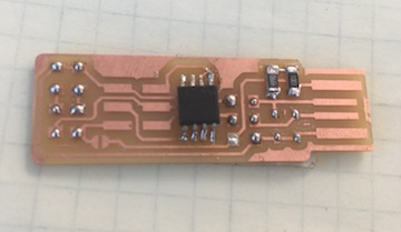
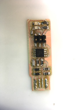
After trying the Windows-running-Ubuntu machine again with my Node Boss, he suggested that I build Neil’s hello-world board to try the Atmel ICE on. Did that. Here’s my board. I followed the steps as above:
- Download the png files for traces and outside cuts
- load them into the mods. Check to make sure I have clicked on 1/32 for traces and 1/64 for outside. Check that the height says 0, not 10. Check that the outside cut will be 3 times. Create the rml file
- Use the interface for the Roland SRM-20 to load the traces rml. Change the end mill to 1/64. It did a beautiful job!
- Change the end mill to 1/32 and load the outside cut into the mill. That did a great job, too!
- Followed Neil’s instructions for the board: Gather the parts (and tape them onto a piece of paper), pre-tin the board, solder the pieces onto the board.
 check the mod settings
 mill the board
 gather the parts
 pre-tin the traces
I was pleasantly surprised to find that the board easily responded to the “make” command (I had to change the “programmer” identifier in the makefile to tiny44) and then it responded like a champ to the “make flash” command. I finished up the commands, hugged my little hello.world board, and that’s when I knew I would have to rebuild my programmer board
 .
.
Blair suggested that I try just replacing the tiny45 chip but I lost most of the traces when I tried to remove the old one from the board. It made more sense to rebuild the programmer board from scratch because it had been my first try at soldering (my first try at this entire process, really) so a second try would produce a better board.
Rebuild the programmer board
- I used brand new png files for the traces and outside cuts. (Brand new–meaning that I re-downloaded them from Brian’s page)
- load them into the mods. Check the settings.
- Use the Roland interface. Change the end mills. Let the machine do its work.
- Gather the parts
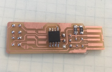
- Solder the parts – being sure that all of the parts are facing the correct direction.
I made this board slightly different in that I didn’t add the USB connection. I just put solder on the traces in the USB spot. It plugged into the computer just fine by itself.
The Proof is in the Pudding (That’s an old saying. I’m not sure what it means.)
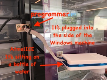
- Plug the programmer board into the Windows machine running Ubuntu. (see picture above)
- Attach the 6 pin cable connected to the Atmel ICE. Red light and green light both came on.
- Change the Makefile back to tiny45 (I love that Ubuntu uses Terminal..just like Mac…)
- Run make command…created the hex file
- Run make flash command
....wait for it......
YES!
Elation is Short-Lived
Sadly, the next step was not successful. The programmer board would not accept the final command to blow the reset fuse: rstdisbl. This will take more time, I fear. I must be 50 - 60 hours into this programmer. Sigh.
months later in a land far, far away
Now that Parallels is working for me, I thought I’d take another stab at flashing my FABisps but neither of them worked.
I downloaded the files again from the class website tutorials and put them through mods to re-create the files.
Then, using the Roland SRM-20, I re-milled the board
and
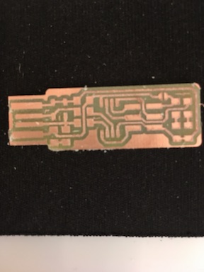
And gathered my parts again:
It was REALLY nice to be able to do all of these things easily.
Soldered everything on.
Plugged it into my HooToo hub and said “make flash” and got the correct response:
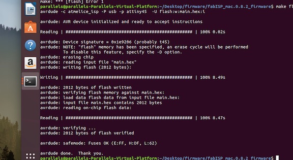
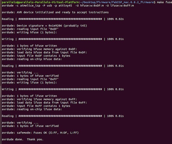
Then “make fuse”
And got the correct response:
Now plug the usb into the computer to be sure that it is working correctly. I ask Terminal to list the usb connections: lsusb
It shows me “Multiple Vendors USBtiny”.
Now I need to change the bit that will turn the ATtiny45’s reset pin into a GPIO pin by typing in Terminal: rstdisbl.
Last, on the board, I disconnect the VCC1 from the Vprog pin on the ISP header by removing the bridge on the solder jumper.
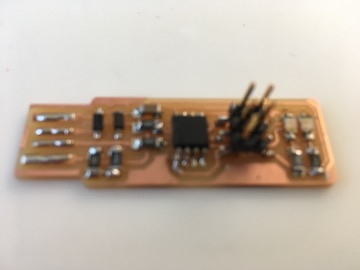
Finally! I have a tiny programmer.
Extra Credit
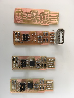
It took months of work to get to a place where I can draw, create, solder, and program this board. It took building at least 4 complete programmer boards before the system worked the way it’s supposed to. This is a unit I believe I can teach successfully at the high school level and no student will experience a problem that I have not personally experienced before.
Here’s my hero shot: