Week16 - Machine Design
-Limit Switch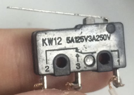
Limit switches are typically used as end switches for machines, it is a precaution of when machines comply to our bad commands, or sometimes they don't comply as they should. It is also used for homing machines, like finding the edges of the 3D printer print core. It can be used even as a button, it is infact a switch, it can be used as a lot of things if you are creative enough and you need to click something. This is called 12KW LimitSwitch, some sites refer to it as a microswitch. The pinout of this is as following. 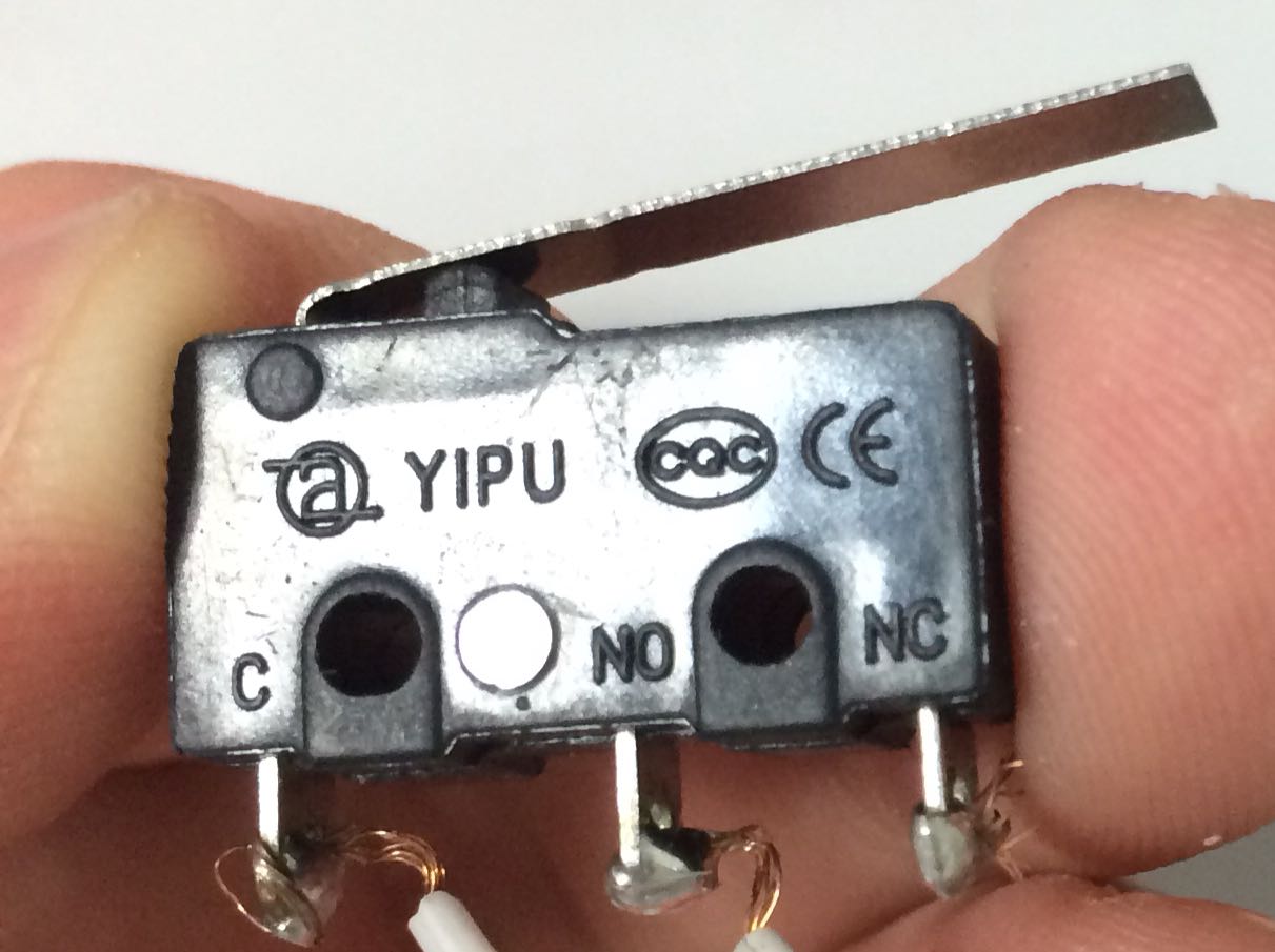
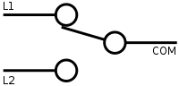
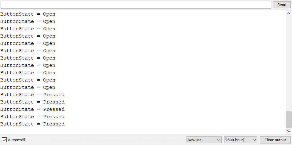
Ref to the right figure here. C = Common, NO = Normally Open, NC = Normally Closed. The figure on the right explains NC as L1 and NO as L2, it is a literal explination, the NC pin means the pin is normally closed as you see. You want your electricity to go through the C, The NO and NC can be used for different pins. I did a small check to see if everything is alright, and used an arduino, uploaded code to it, and checked the serial monitor. 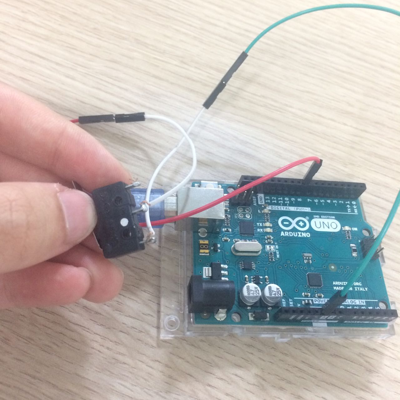
Then since we were using the CNC SHIELD for our machine design group project week, link here i had to figure out a way to connect the switch to the cnc shield. after many useful videos i found out how to connect them here, and figured out that the CNC shield has special pins called End Stops, which you can use the limit switches with. 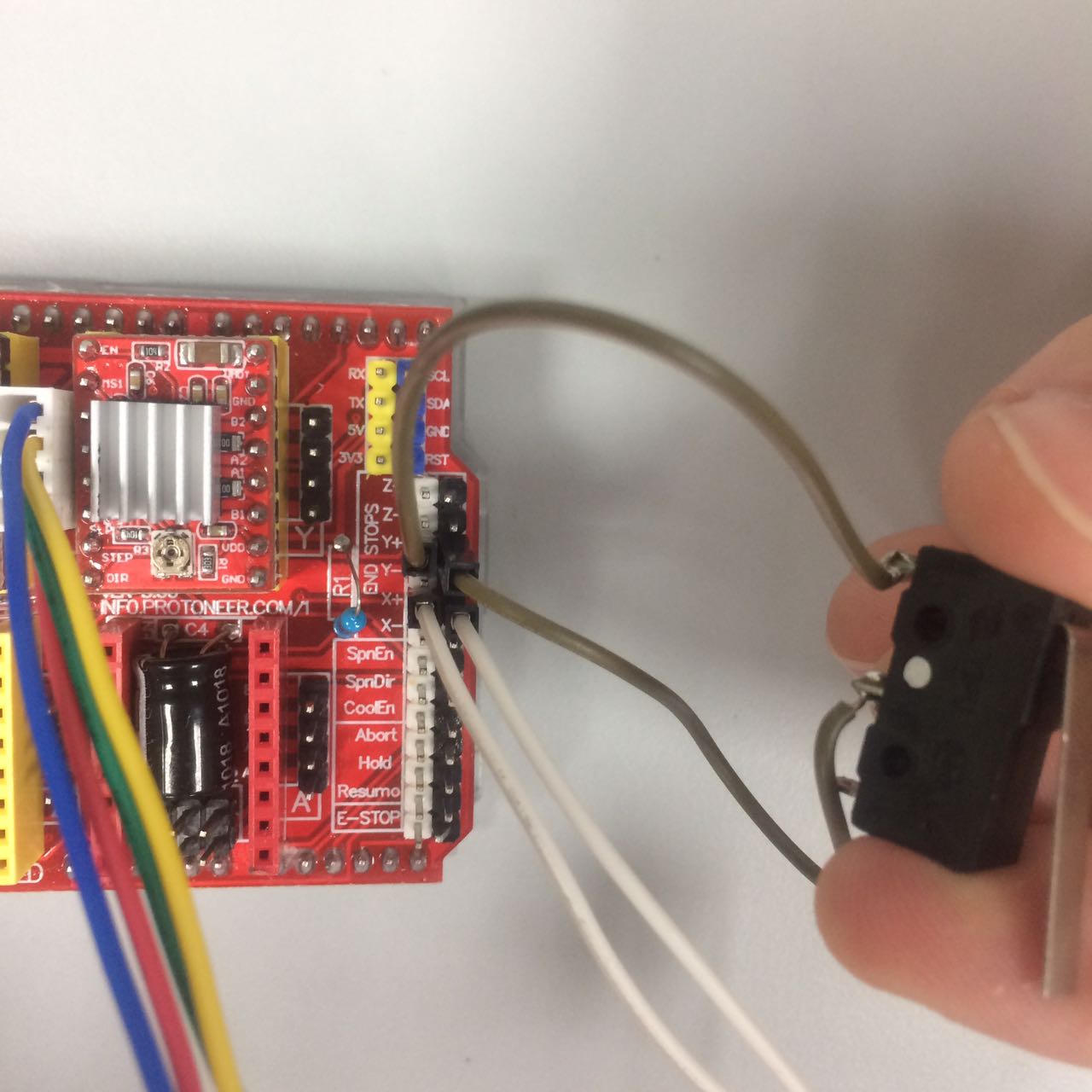
this means that the above is set at the x+ axis, C to white and NO to black, from the videos i also learned that the Universal G-code Sender software has the limit switches already set in the code, you only need to attach it to the pins and enable the "Hard limits" which is $16=1(This is a command you type in the Universal G-Code Sender), 1 means true as this is boolean, once you got that you can simply test by moving the x-axis a little bit and click on the limit switch while it is still moving. Now it stops and shows you this message. 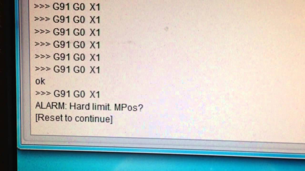
Image is not from my machine but i got the same exact alarm, Image Ref. So I was done with the End Stop, now i had to start researching how to home using the switches, it was confusing at first, because i didnt know if the pins would be in a different place or not, when i found this link[must have link] i understood that $17 is the home enabling variable. I also learned that they usually are the "+" in the CNC shield and if i wanted to connect them in the negative "-" axis, i have to enable $18 homing dir invert mask. so this was my setup and it worked. The home connection in the CNC shield is exactly like the above picture, the White wire. This is done by connecting NO to X+ so its the homing of x-axis switch. today is 16-May, tomorow is the presenting day, I hope there is still enough time to figureout how to attach them cleanly, but we might have to improvise. Download Ino file here. -Universal G-Code SenderI did help with uploading the file, for some reason it didnt work for them, but i'll show you the things i changed. 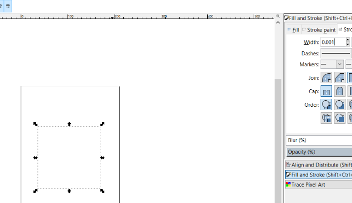
This is a circle, it is 0.001mm which is hairline for inkscape, i changed the page canvas to be 1mm bigger than its size. 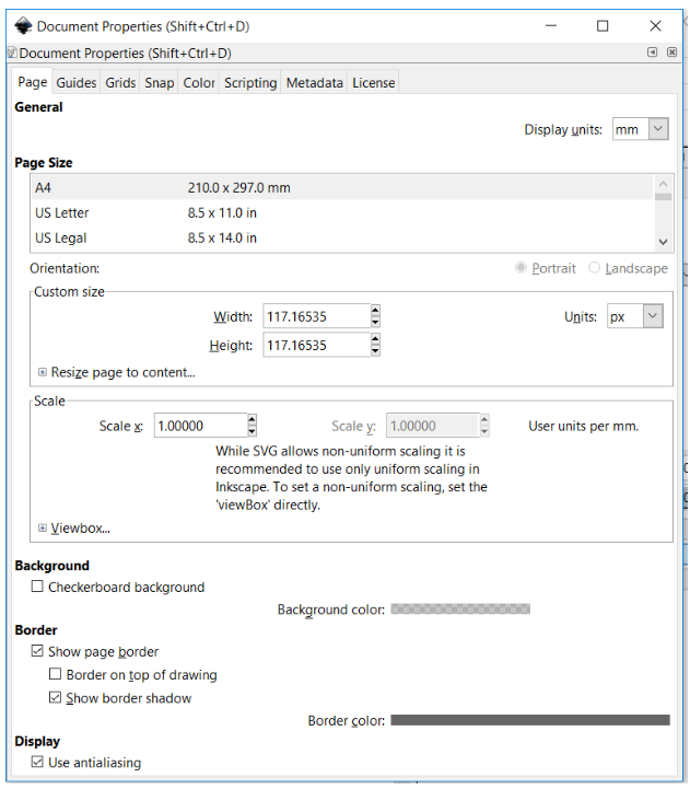
As you can see it is in px instead of mm, I could swear i had it on mm and it worked for me, but later on, we kept getting an error, chaning the mm to px for the page canvas solved it. Anyway, then you "save as" later on you will choose G-Code as the extension of the file, you will get this window. I Changed lots of values to Zero since we didnt have a Z-Axis stepper, we have a servo, but we still cant get it to work for some reason.(We will see tomorrow) I also unchecked a checkbox in the Registration tab, didnt think it was necessiry. (note it works without most of the settings Z-axis settings and the checkbox, but this is my setup) 
and it works. -Clippers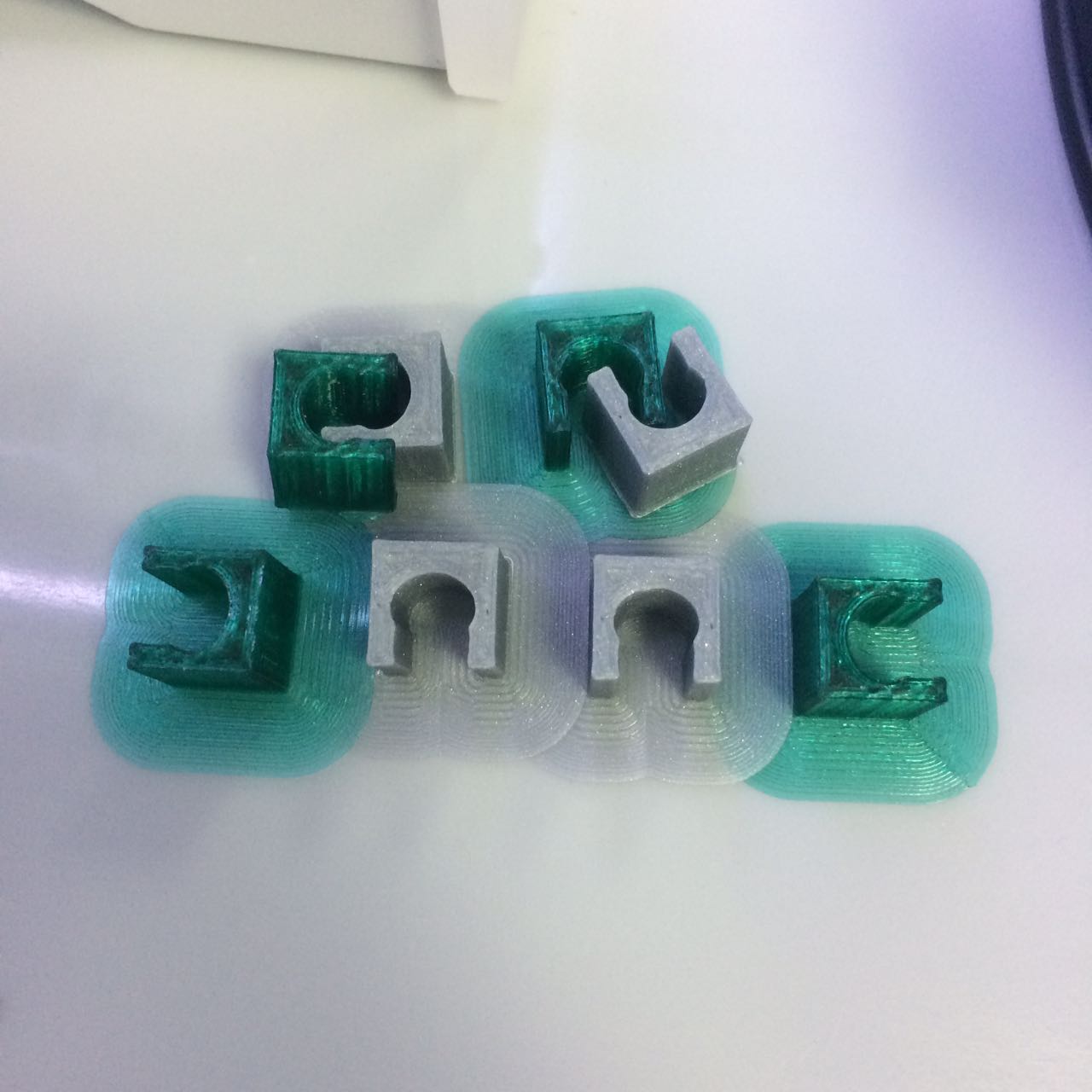
We needed to keep the wirings cleaner, i thought why not try to print on the 3d printer, PLA, few minutes later. 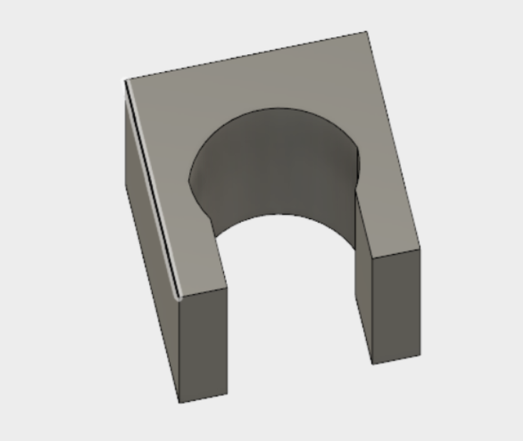
This is actually the second design, the gap is wider by 1mm in this, first one broke, too tight. It works! from the second try. 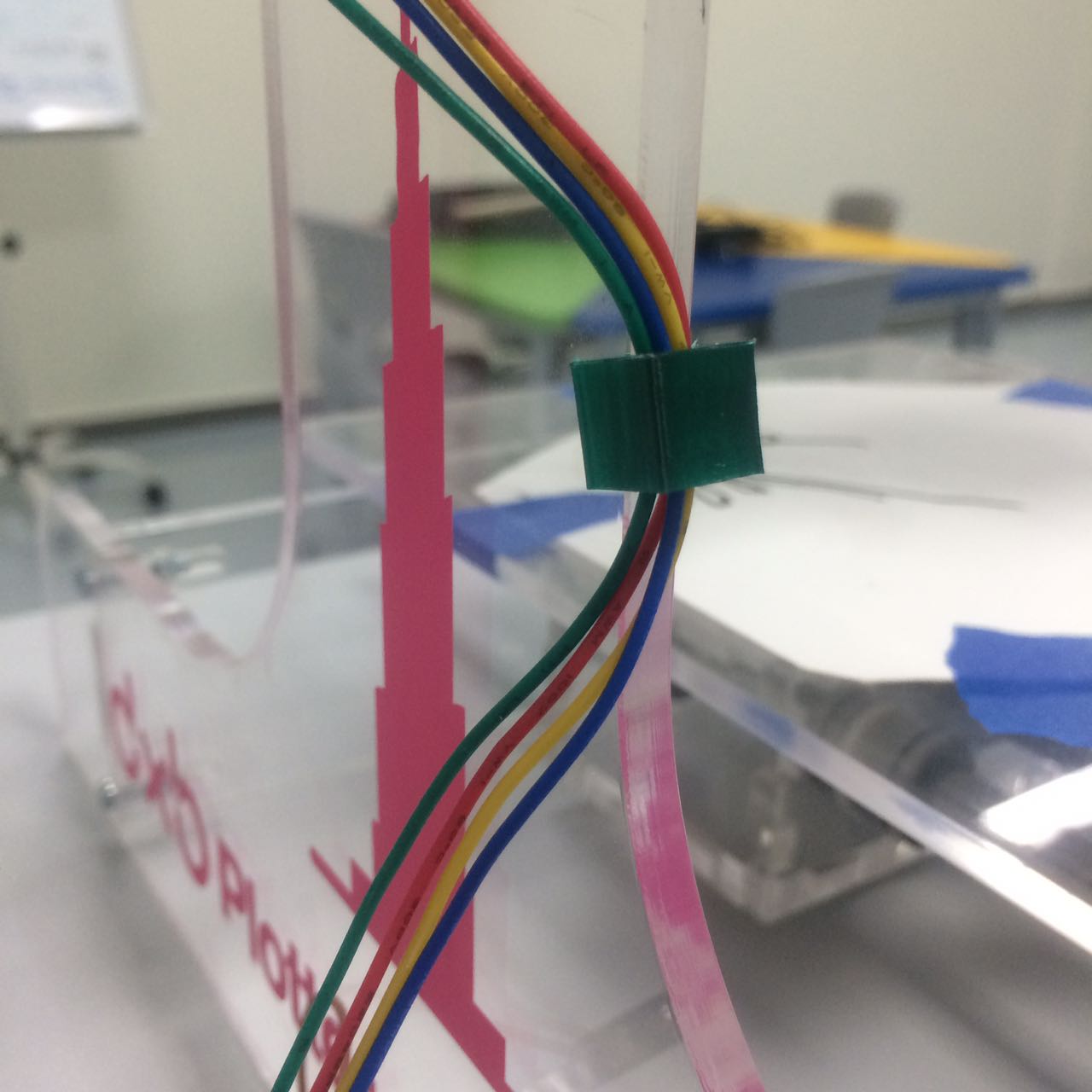
Download fusion file here. |