Week14 - Networking and Communication
Network CommunicationDescribed your design and fabrication process using words/images/screenshots. There are 2 types of communications, wired and wireless, I used the wired technique called serial bus, for the wireless there are bluetooth and wireless modules. I did have some expeirence with a bluetooth module once, but i forgot everything except i remmeber it wasn't that hard and it can be very similar to the Serial bus. Board DesignI actually didnt design a new board for this week, i used the one we designed in Week07. You will find the Schematics and the brd file over there along with the PNGs you can use to do the milling. 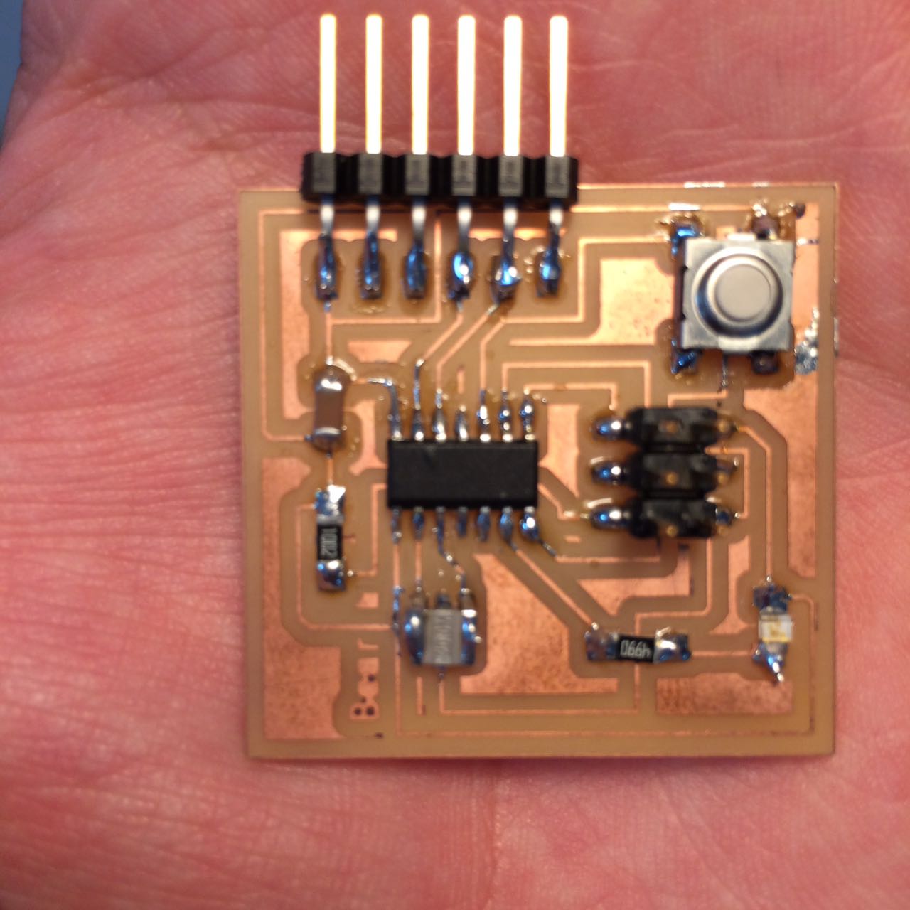
However what you really need for this week is to have 2 boards with an FTDI header that has the RxD,TxD pins connected to it and the microcontroller chip you are using, in my case attiny44. 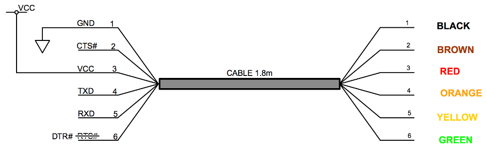
You will definatly need an ISP board for programming. 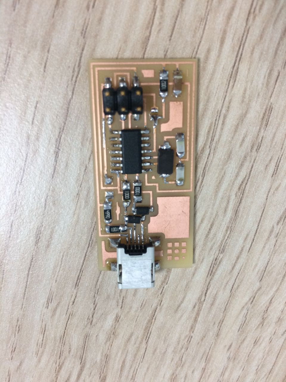
That is basically all you need for the easiest serial bus communication. Arduino CodeThis is divided into 2 parts, reciever and a transmitter. TransmitterI included a softwareserial library and namaed it myserial, i needed the softwareserial because i am making a serial bus, as you can see, if the button is pressed, the Red box code will work. In the Red box is an if statement that checks if the button is pressed, and as soon as it is pressed, it writes to the serial the charcter '2'. Delays are only added so that it doesnt spam too fast. Also in Green i wrote an explination of how to flip back the LOW and HIGH. Reciver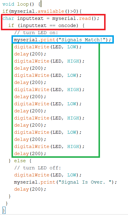
In Red a Char variable called inputtext is given the value of the serial read through the FTDI on the board. the Blue is a debug print for me, i used this to know exactly when was the momeny the board calculated the match. Green has a blinking routine i programmed when it recives the right signal. Testing Communication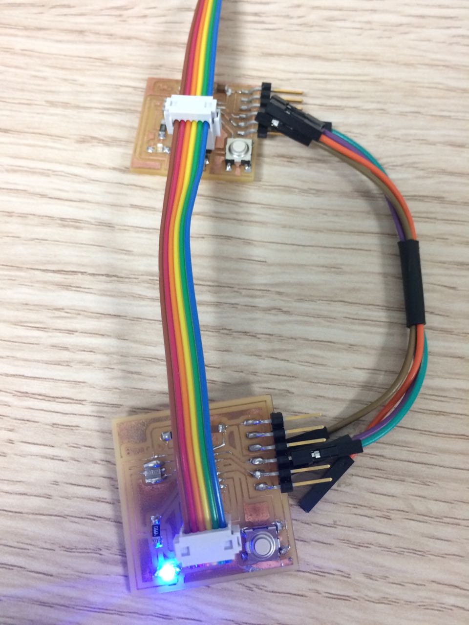
For powering the board i actually used one of these boards, dont remember which exactly. 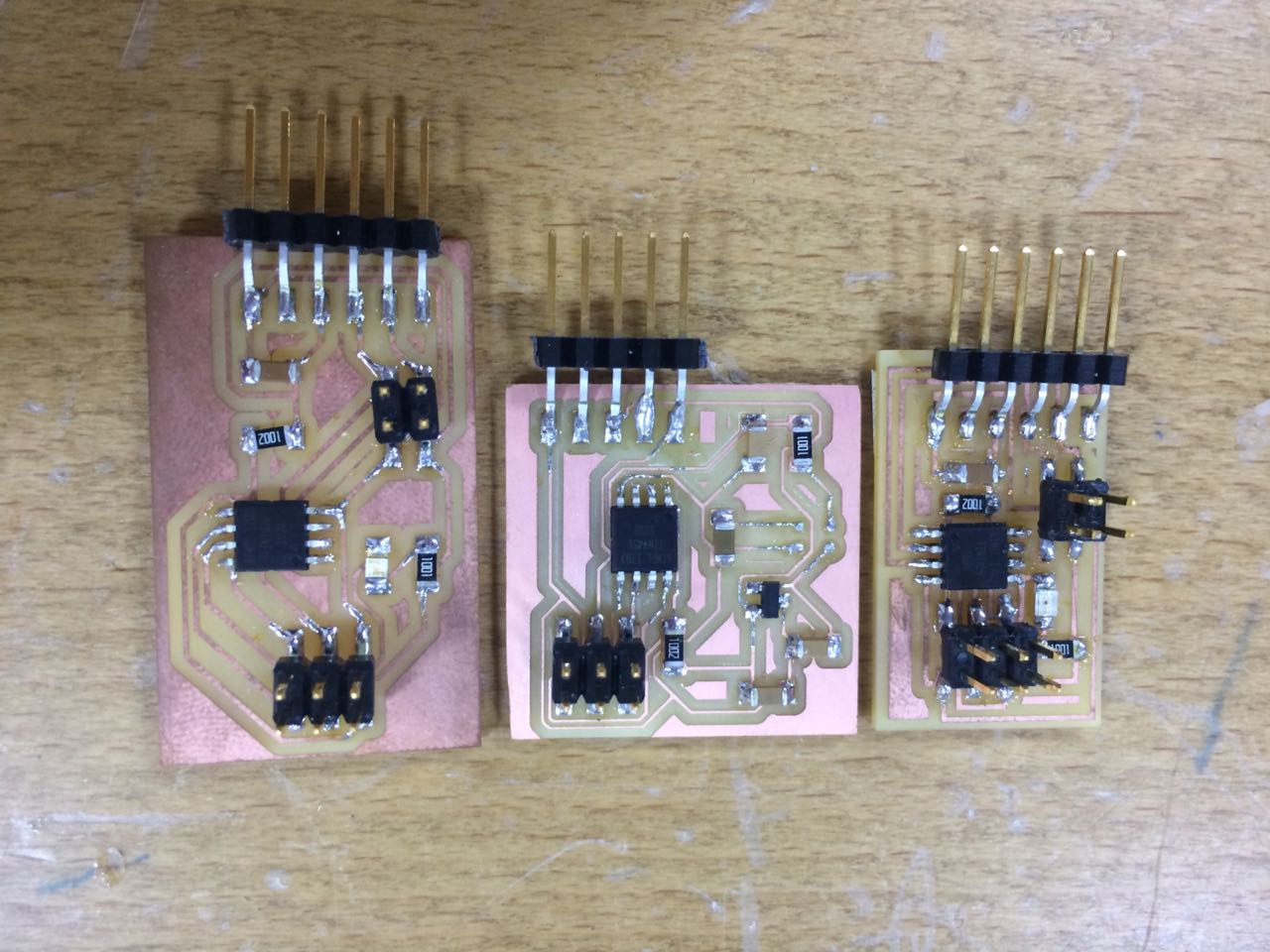
I found them in this pile at the lab. 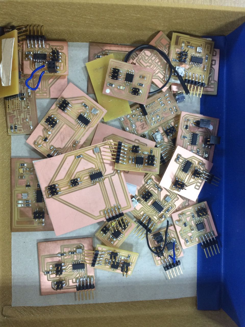
I looked for boards with an FTDI Cable and ISP headers, that is because i wanted something simple to power the boards, FTDI cable fits in it's place, then the ISP cable transfers the power to the other boards. 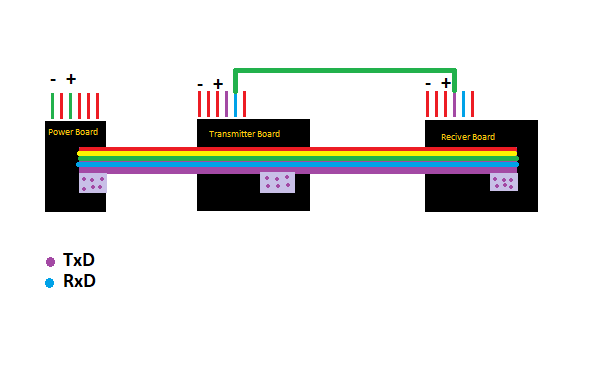
There is a wire from the RXD FTDI pin from the transmitter and to the TXD FTDI pin on the reciver, this is flipped because in the arduino code i flipped the parameters when decalring the software serial (Rx,Tx) i used (0,1) it should be (1,0) because if you see the schematics below. I am only using 2 pins on the power board, Vcc and GND. 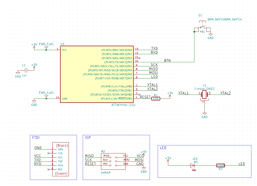
Flipping back the numbers will fix it, then you will need to flip the wiring back to the correct standard of connections, there is no right and wrong here, just good and better practice. Below is a video of the working communication, notice how the transmitter on top has slow blinking at first and the reciever is in a constant state. As soon as you click and hold for a bit the Transmitter LED becomes constant and the Reciver blinks fast. Download the Transmitter arduino code here. 3 boards NetworkI can actually use the ISP headers as pins to connect another board and i think logically speaking i dont need to use the wire from the FTDI pins RXD and TXD, i can just assign MISO pin as TXD and SCK as RXD, and change the pin numbers of the softwareserial rxd,txd to the appropriate pins of MISO and SCK, this way i can use as many boards as it is physically possible for the circut to handle, surely there is a limit. In this demonstration below i used the MISO pin as RXD and MOSI as TXD. 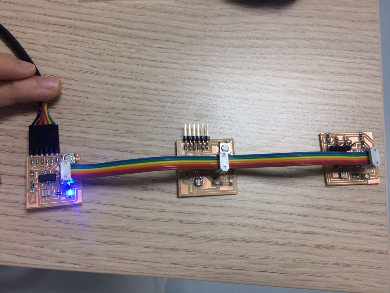
The board with the blue LED is the Master board, the rest are slave boards, I have done the programming for them in the arduino code. Demonstration is below. Download Ino Master file here. |