Week12 - Output Devices
1-Piezo BuzzerI found this buzzer in the lab, sadly nothing was written on it so i didnt know what model it was, i just recognized the buzzer because i was looking for one earlier on google to get one for this week. and i tested it on the arduino, sure enough, it makes noise. xD 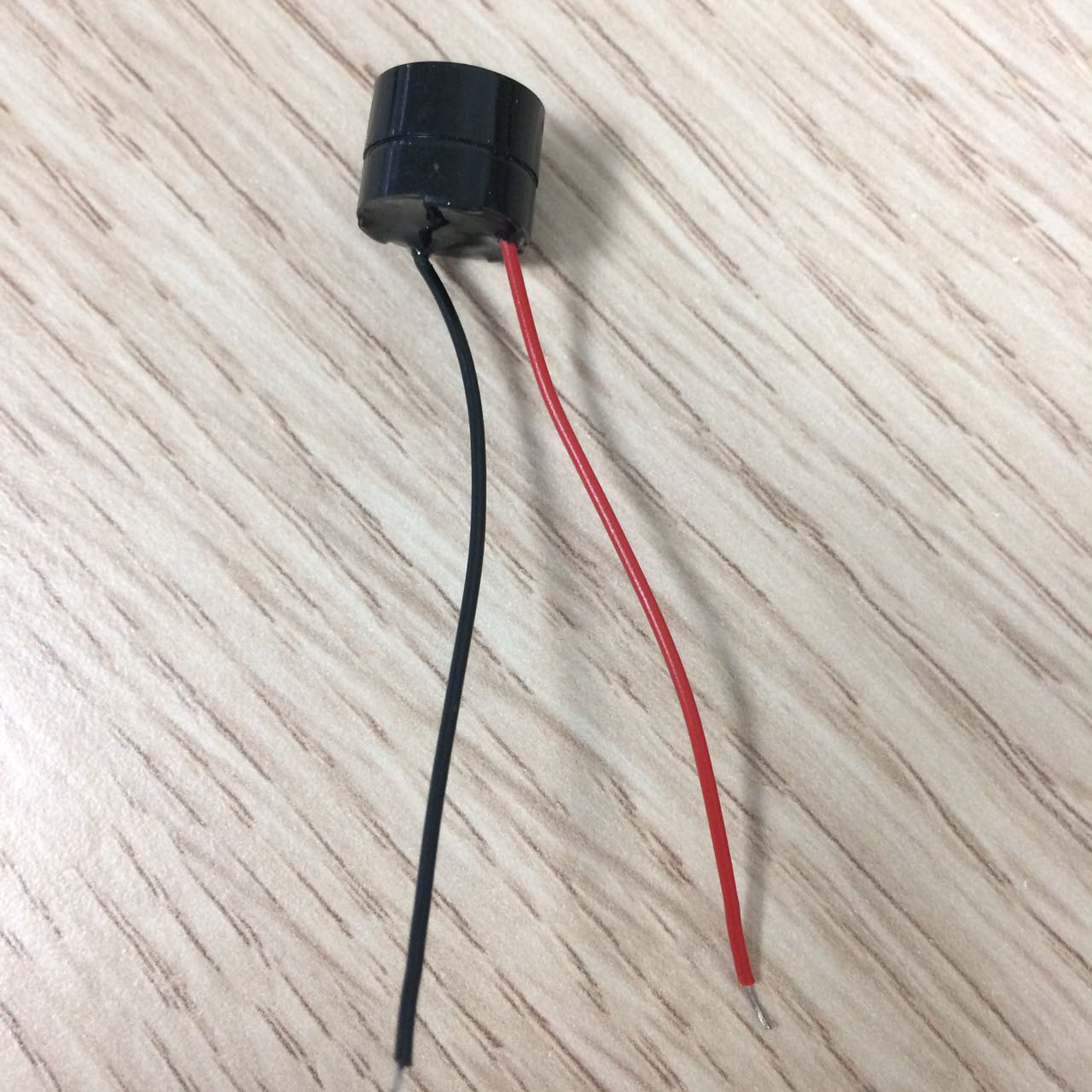
I tried to look for the buzzer datasheet, it is not clear but i think i got the right datasheet, i just looked for the buzzer that looked almost exactly the same to find some more information about it, that did not help a lot, i only found out it can take upto 30 volts of maximum input volatage. Board DesignI used eagle again for this week, and started working on the schematics, first i had to know what components i needed, sure enough i made a list. 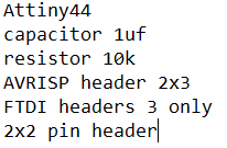
I didnt use a resonator on this one, i was gonna use the internal clock 8Mhz, and i only used 3 pins of the FTDI header because i only wanted to use that as a power source. 1-SchematicsSame process of the schematics, just adding components from the fab library i already downloaded, connecting everything together and done. 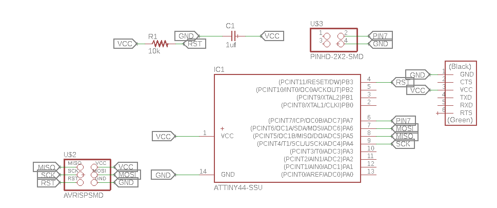
2-Board DesignFor the board design i used autoroute to do the traces after moving the components to where i wanted them to be. 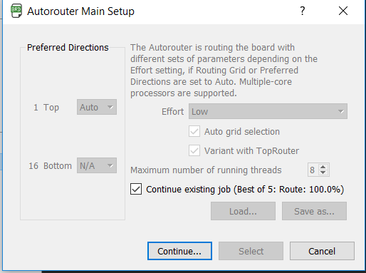
100%! I love to see that, traces were perfect in one button click. Just had to make sure everything is alright, that didnt take a long time, i dont have many components. 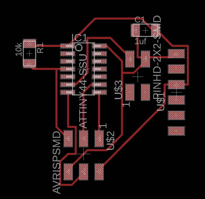
Everything looks great! 3-Milling the boardYou need to export the board into a PNG so that you can convert that to RML, i use fabmodules for that. before you export the board, you need to turn off all the layers except the top layer, thats all you need. After you choose all the right configurations on fabmodules and calculate, just click save to download the rml file. for the outline or the board cut area, I use MicrosoftPaint, I open the traces PNG file previously exported from eagle, then I just cover the board with a filled white square and make sure thre is just enough black borders for The CNC to cut, and i save it as Outline, then i go on with the fabmodules process and choose 1/32 mill bit instead of 1/64 for the traces. 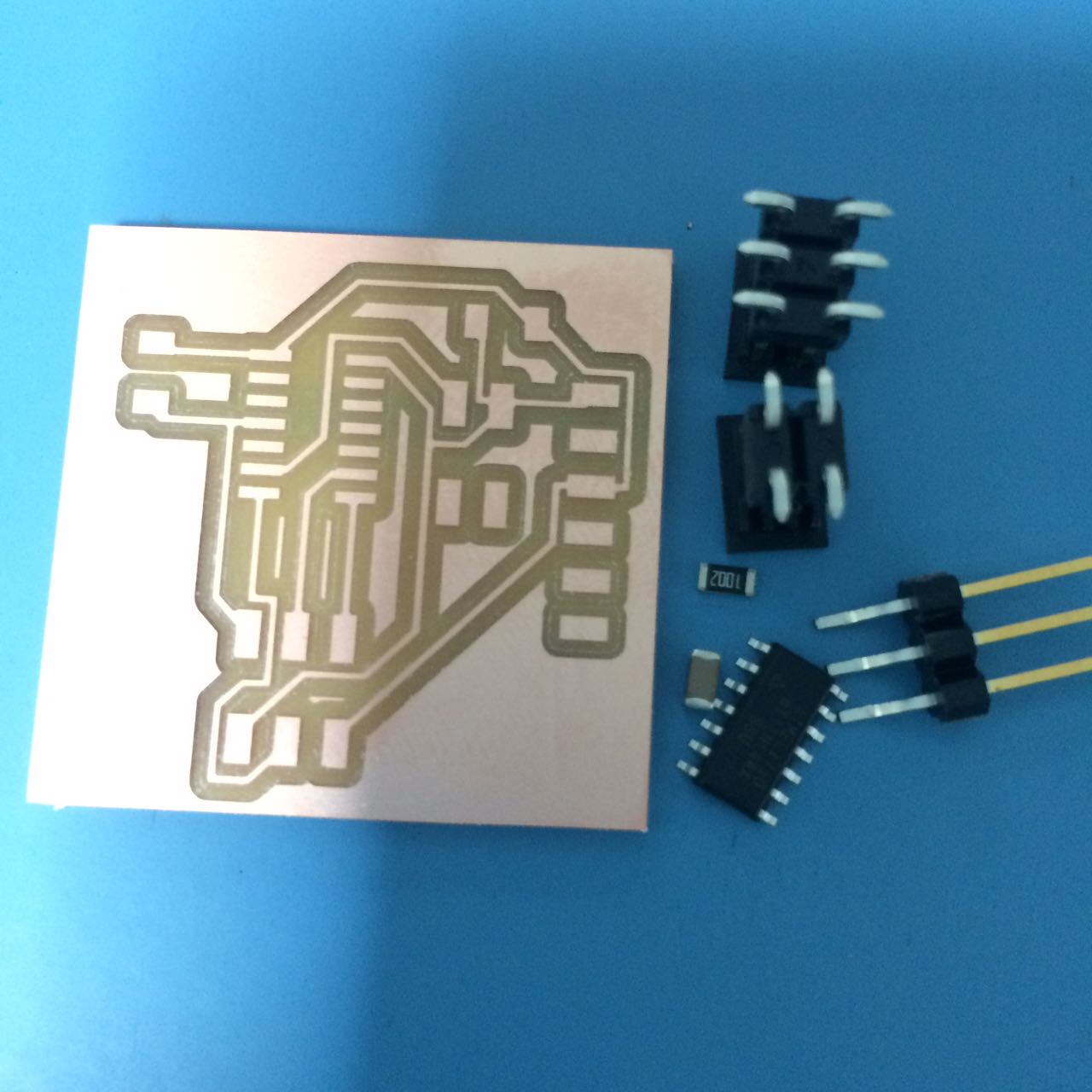
Board looks great! time to solder the components. 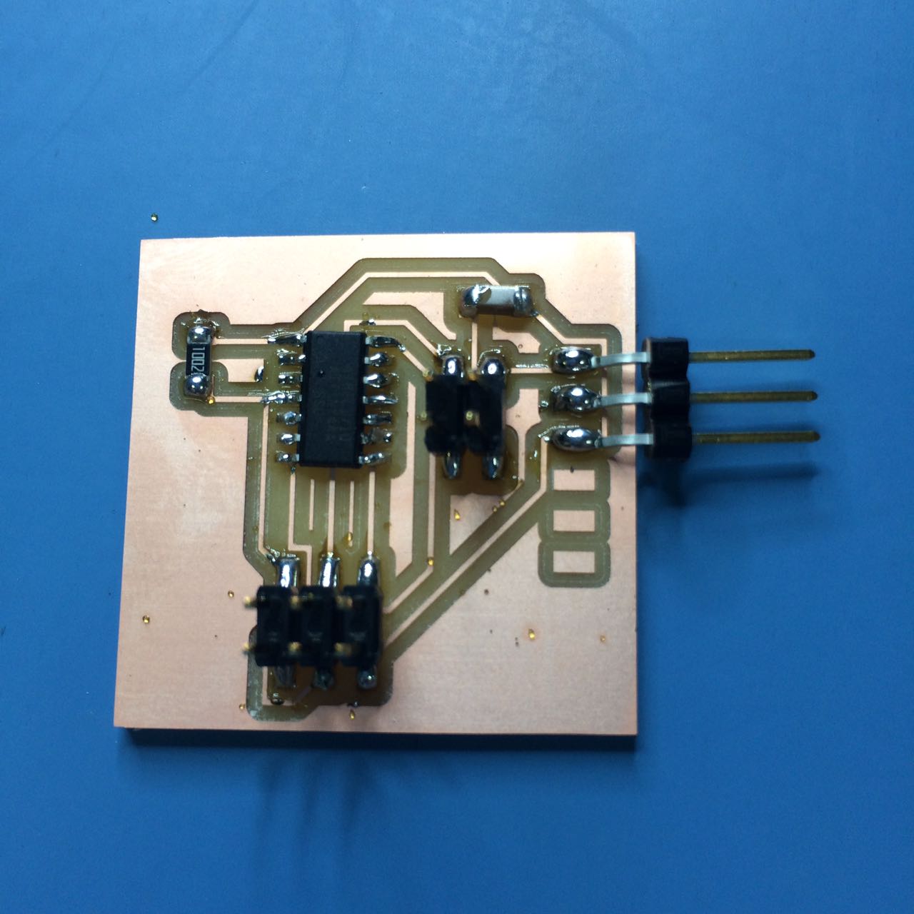
4-Programming the boardI found this amazing tutorial that explained what you need in order to program a buzzer with an example code. So apparently what i am looking for are these functions below. A quick search for the function page and you understand some more details, like "It is not possible to generate tones lower than 31Hz." I modified the code so that it can go through frequencies from 31Hz to 1000Hz with a delay between them. I understand that there is no reset for the k variable, once it reaches 1000 it will stop. but it will take some times and it is okay. Download the Arduino Code here. I will measure the power consumption of an output device on Week20 Will be there as soon as I am done with it. and i will probably update this later. |