Week05 - Electronics Production
-This WeekFor this week, we are going to create a FABISP board, to understand what it is, you need to understand what few other things mean: The FabISP is a board used to program AVR chips on other boards if they have the needed ISP pins connected to the AVR chips. that being said, I am gonna create this particular FabISP board by Anna Kaziunas. This is my first time doing something like this, and probably the first time working with any board really in my life, i dont have much background on electrical either. The FabISP is a board that replaces the need of commercial products such as AVRISPmkII by atmel 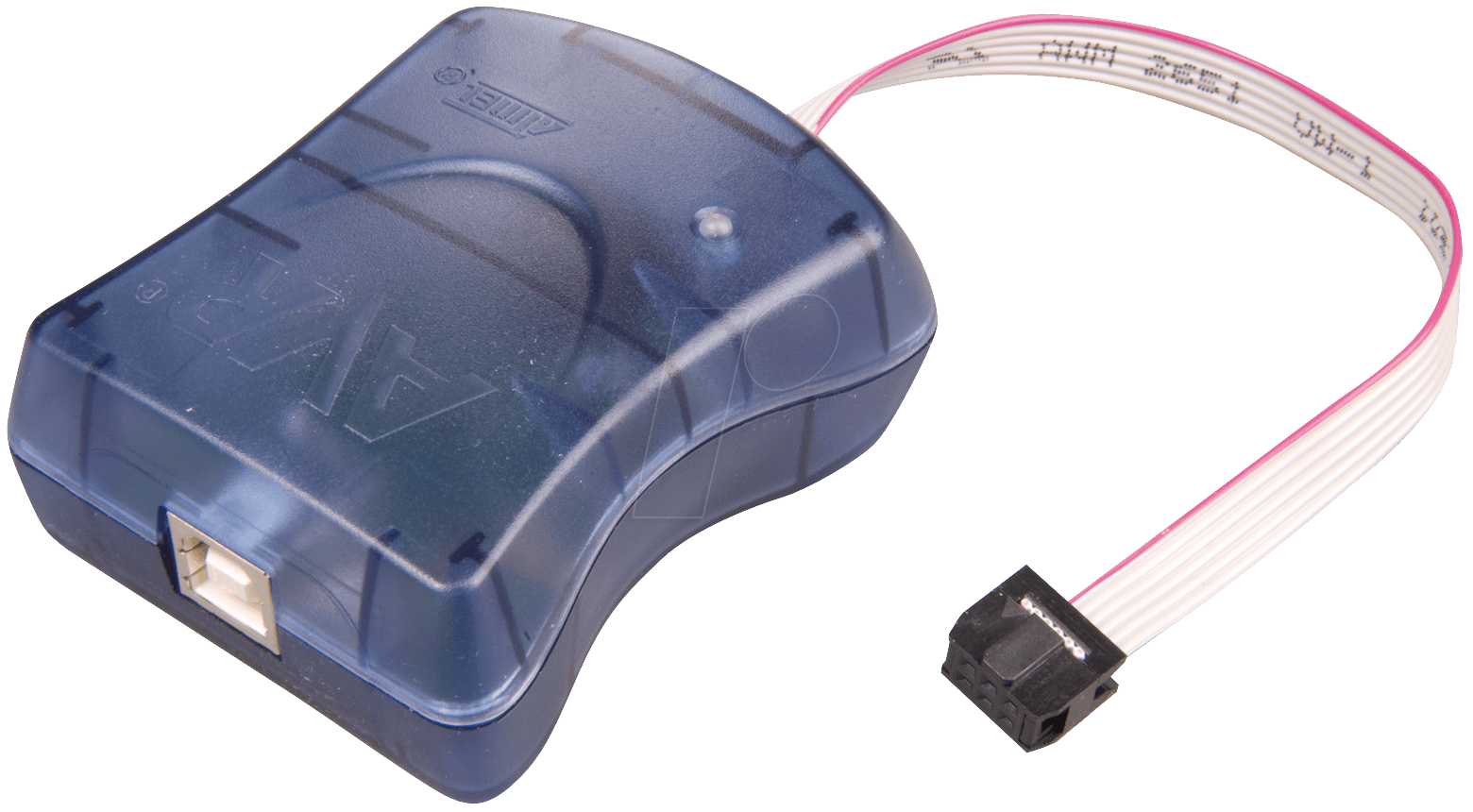
Image Ref here. -CNC MachineThe CNC Machine is Roland SRM-20. 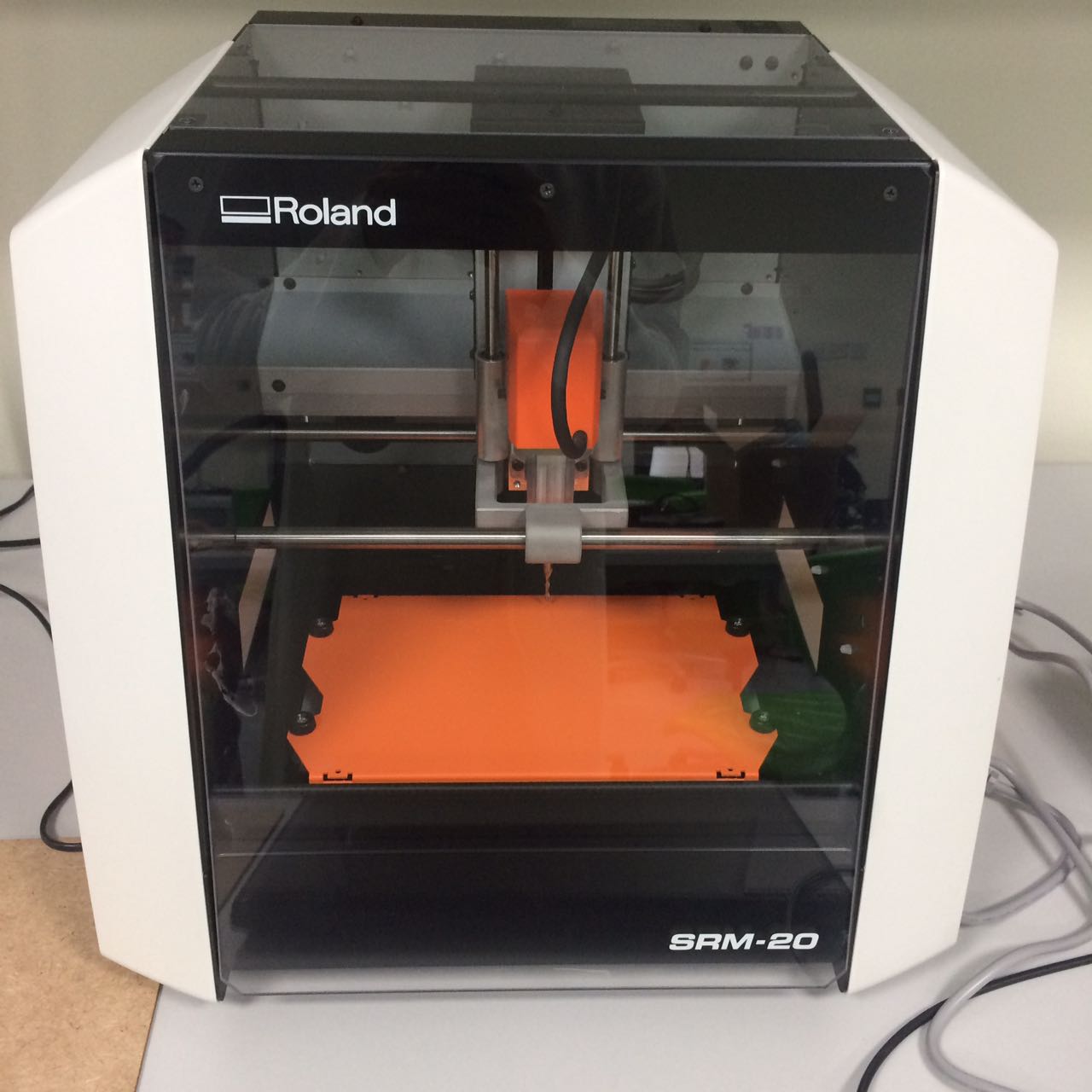
it was used to get copper board ready from the designs given. 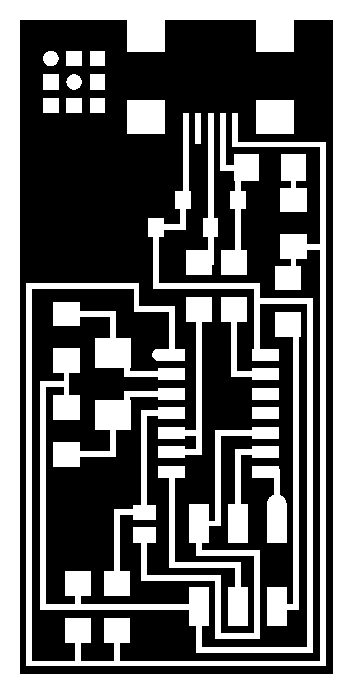

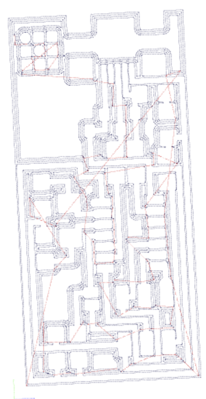
first step is to use fabmodules.org to produce the right format file(rml) from the designs above, you simply find your png designs and upload them, then you choose which file format you want to get, which in our case the roland mill (rml) format, you then need to choose what process you want, so for the traces pick traces and so on and lastly you choose the model of the roland CNC, which in my case was the SRM-20, then you need to choose your process is it traces or outline cutting. 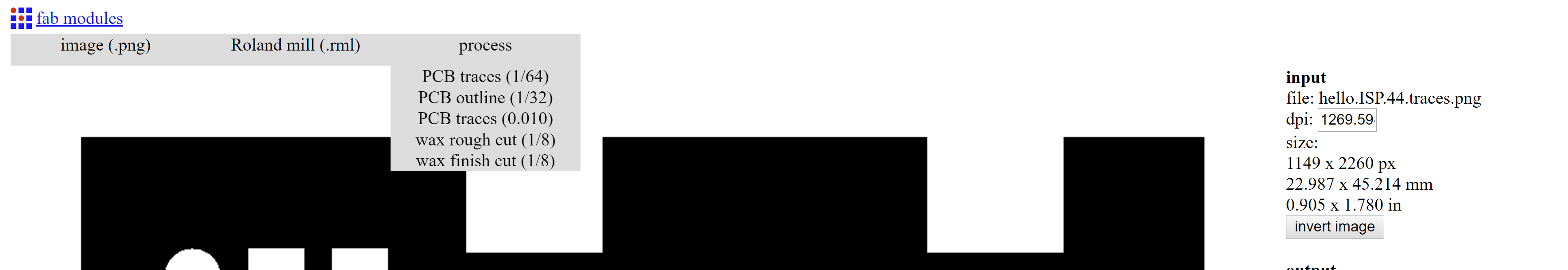
After that you need to choose your machine and set the values of x,y and z to 0. You will notice that other values change once you do that, lastly you press calculate and you get the following. 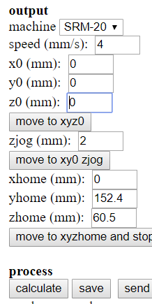

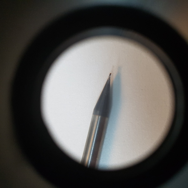
Changing the bits is very easy, just handle them with care and remember that each one is used for a different job, for this board i used 2 different bits, the 1/64th one which was used for tracing and the 1/32Tooth(Just ask Wendy[Hyperlink her]) one, it was used for the interior the final cut of the board. 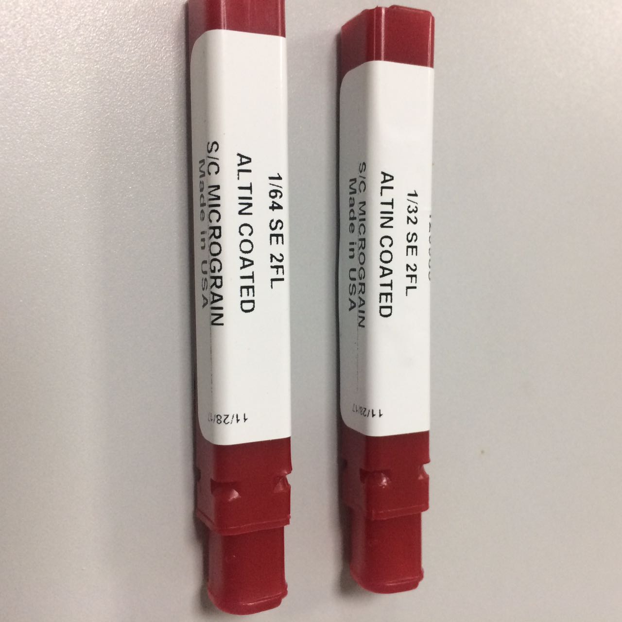
Using the machine is very simple, There are control buttons on the Vpanel software below, this allows you to move the bit around while the protector door is closed. It shows you the speed, and you can do things like turn on the Spindle, to heat it up or whatever other reason you might need that for. The "Move" section has preset buttons, like View, this will move the bed towards you and move the bit away so you can examine your board or pull it off, To Origin (x/y/z) this will move the bit to the zero origin that is preset by you or someone else already on the machine, WARNING do not origin the Z, this is like you are asking for the bit to break, i can find little use to that button, i advice not to click on it unless you know what you are doing. The right Section has the Cut speed and spindle speed, cut speed is how fast the bit moves on all axis, the spindle speed is how fast it turns. There is one last thing, the Set origin button (x/y) and (z) This is where you origin your x/y to indicate the start of your board cut, and you origin your Z axis by holding the bit right on the board(actually touching it) then you tighten the screw to hold it in place and origin the Z that way. Then when you are done, just lift the bit a little bit, so it doesn't start turning while it is touching the board. 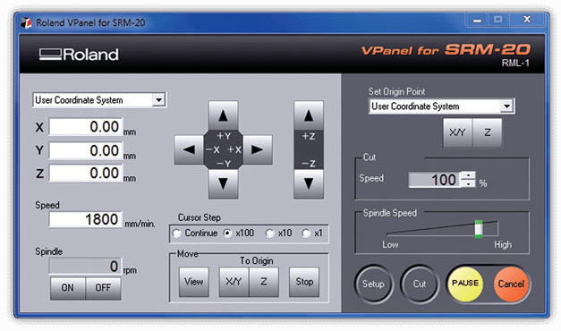
Just origin where you wanna start(x/y), make some space for the board, don't forget to origin the Z-Axis every time you change the bit(Critical process so careful not to ruin the bit), that's about it for the CNC, press cut and add it to the empty box and press Output. 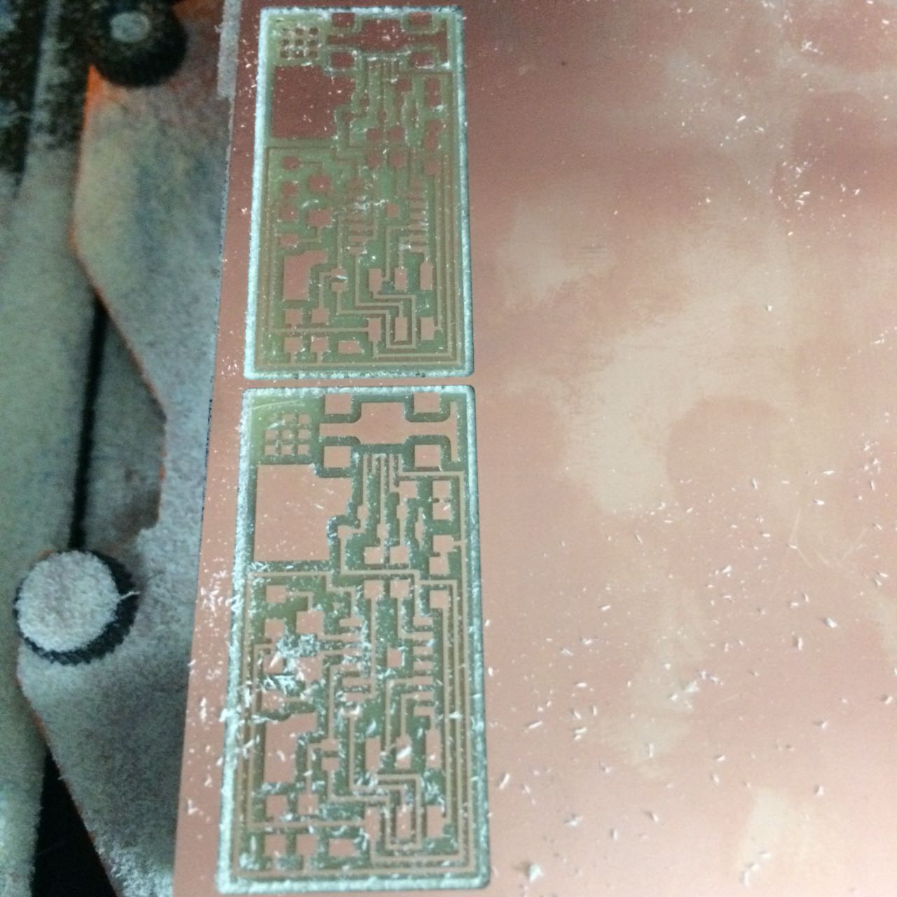
|
-Soldering
|
First step is to get that board cleaned, a clean board surface, helps the soldering process, so water and soap is recommended. next we need to find all the parts necesary for the ISP(In-System Programmer) board, and Carl showed us this idea of using a double tape to organize the parts in a safe way, they are easily lost, i have to say this is so comfortable that i never want to do it in another way. 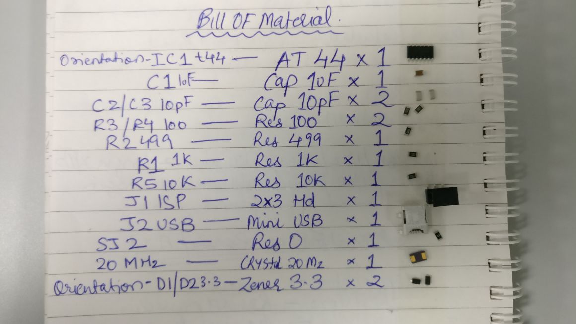
**Note 4-June-2018** 
Image Ref here. Now we Solder! The reference of the design was already given to us in the tutorial, with some instructions of adjustments to be made, and the tutorial also recommended that we solder the Mini USB first, which made total sense because the pins are too tiny and you wanna be comfortable working on that, the soldering process took me 1-2 hours to complete, but i am a total beginner. 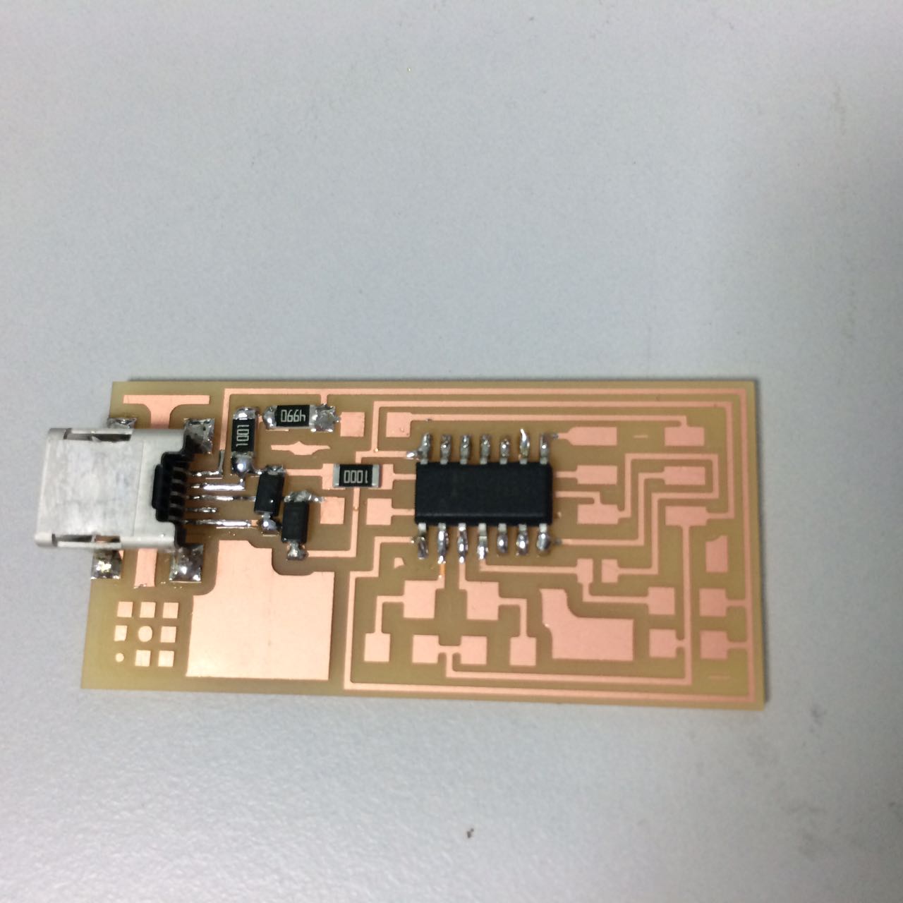
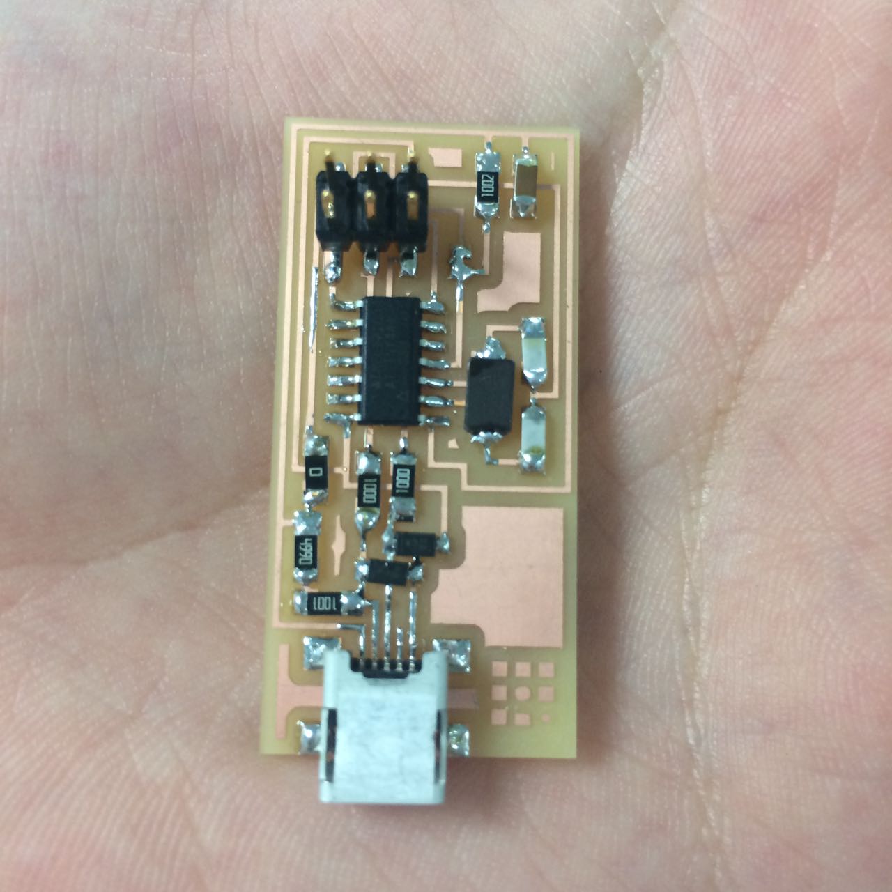
when you solder several boards, you kind of start to get the hang of it, what i got was i heat the surface of the copper, then i add the solder wire and it sticks straight away! the main thing to keep on your mind is that you want to stabilize the component first, for tiny components such as a resistor, i add some solder on the resistor space first, then i hold the resistor with a tweezer and reheat the solder then i put the resistor on its place while the solder is liquid. this works every time! sometimes you get a bad looking solder(not shiny) when you do it this way, you just add some more solder to it after you do the other side, and it will be shiny everytime. The copper board we are using is called FR1, it has a thin layer of copper on top and below is all non conductive phenolic resin, as mentioned in here. There is also a safety concern. 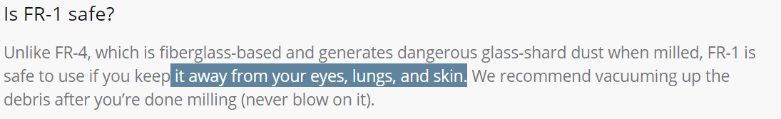
To attach the copper board onto the bed, we first attached a wax block with double sided tape, then we put the double tape and make sure we cover the board evenly because we want it to be as flat as possible, then we stick it to the wax block. The wax block is used as a soft material so that the bit doesn't break, and to make sure that the board will be cut all the way. here is an Image. 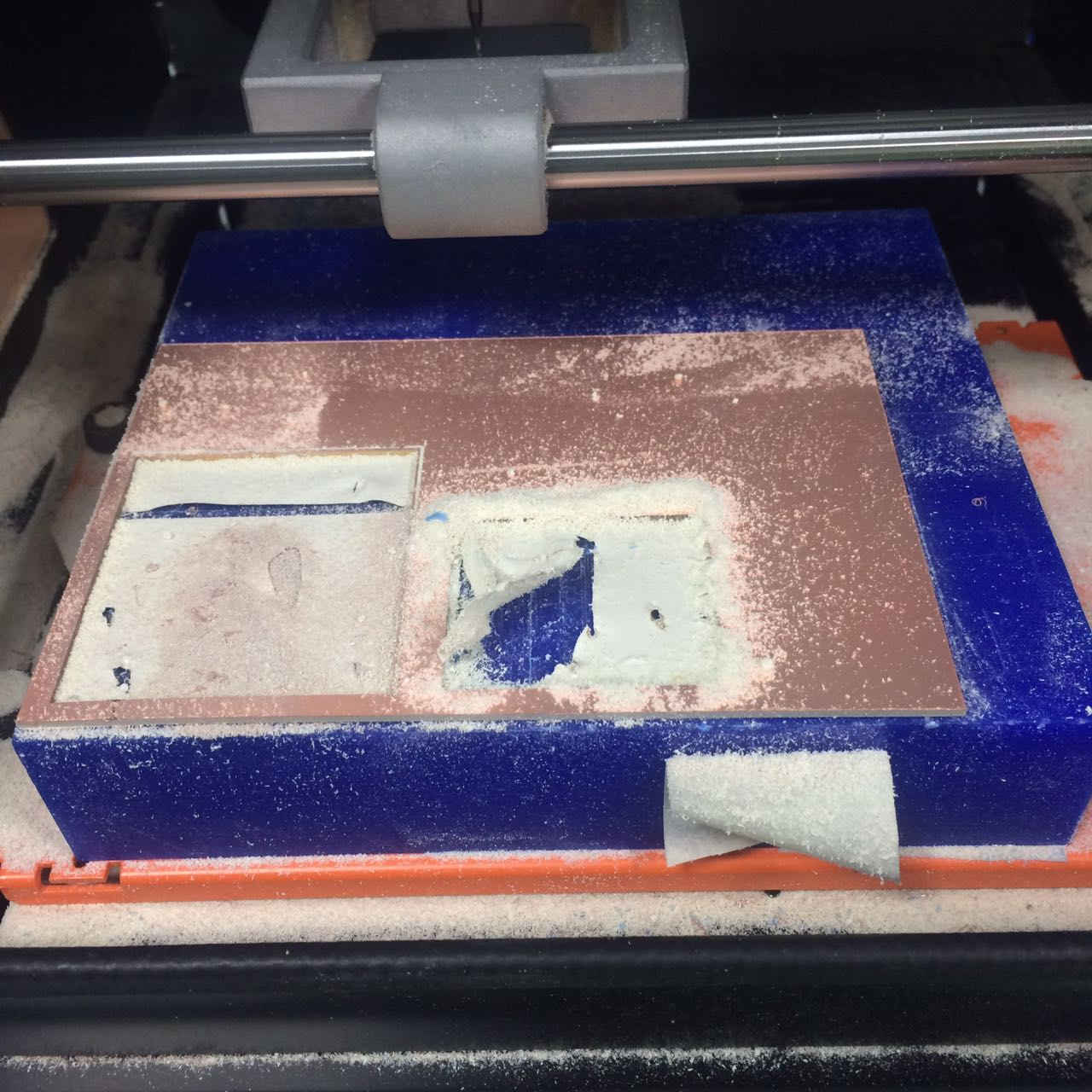
We use these dust brushes instead of vacuuming. 
Image Ref here. |
-Testing the Board
|
Smoke test! which is basically examining the board closely while you plug it in using a USB cable to a computer and waiting for the board and hoping it doesn't get smoky and fried, i also tested using a multimeter to check for some paths of the circuit, if they were touching or even worse not touching. I used the continuity setting on the multimeter, it doesn't matter which wire goes where because i just check on how both paths are either touching or not touching each other. which is a common problem sometimes when you cnc your board. 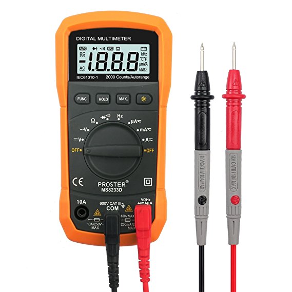
Image Ref here. 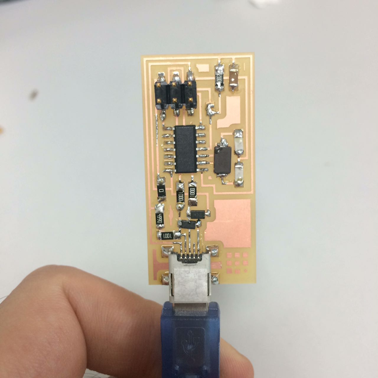
No Smoke~ |
-Programming the board
|
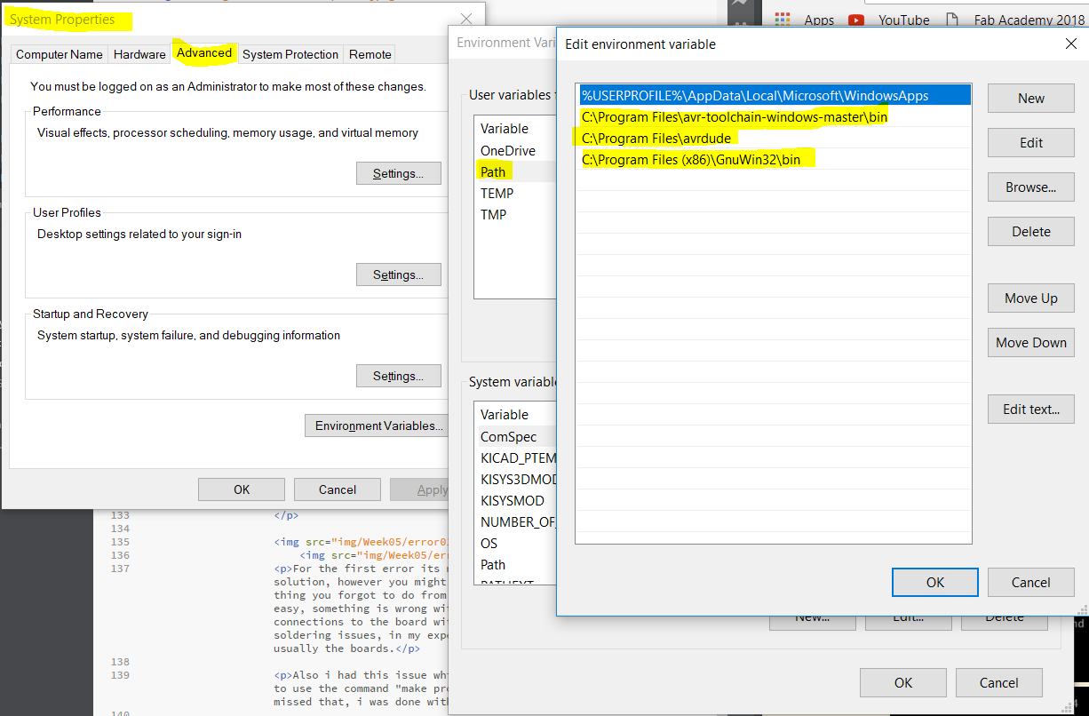
First you need three things downloaded, Atmel Gnu toolchain, GNU make and AVRdude. Then you have to set the advanced system settings Environment variables. You open that window and then choose Path and then edit, which will show you that window necessary to add the three paths. 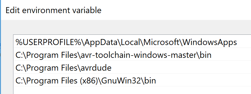
Then you need to install Zadig software, the driver for windows and the fabisp firmware. Zadig was used to install a driver to the USBTiny, more info if you go to their website. The firmware was used to program the board to be an ISP but we had to edit a file as the instruction says. 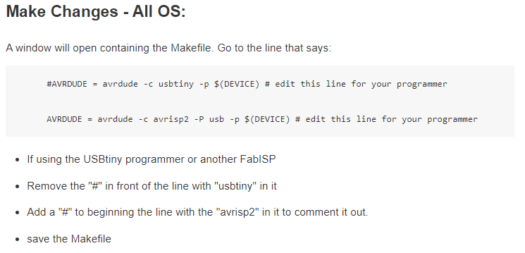
We did this because, the make is different for the avrisp2, so anything else will use the usbtiny make, so adding a # before the avrisp2 line will comment it and ignore it when making, so removing the # before the usbtiny line will activate that line and not ignore it. I also should note you need to connect your ISP board to another ISP board, but that other board should be already programmed in order for your board to be programmed. So we program a FabISP board with another FabISP board. the following connection should be made before you do the make commands below. 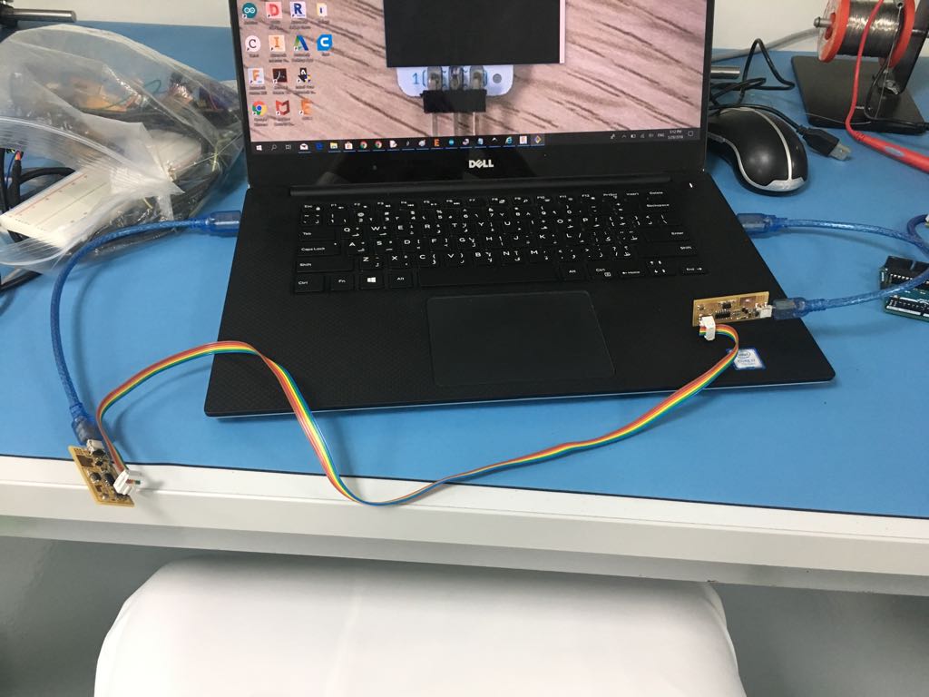
Image Ref to Eidha I am not in the lab at the moment to take my own picture, but this is exactly how we all connected the boards together. Next step as the tutorial mentioned, we need to git bash in the firmware folder and navigate to the fabISP folder. then we use the following commands in order. That is basically it. 
ErrorsThere are 2 errors you wanna look for. 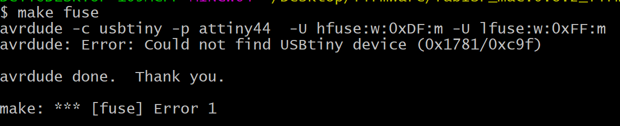
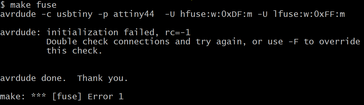
For the first error its not entirely clear to me what was the solution, however you might wanna check your drivers, or any other thing you forgot to do from the tutorial. A possible solution was that i just restarted and then changed the cables or even laptop, however if i had the same problem again i would probably google a solution. 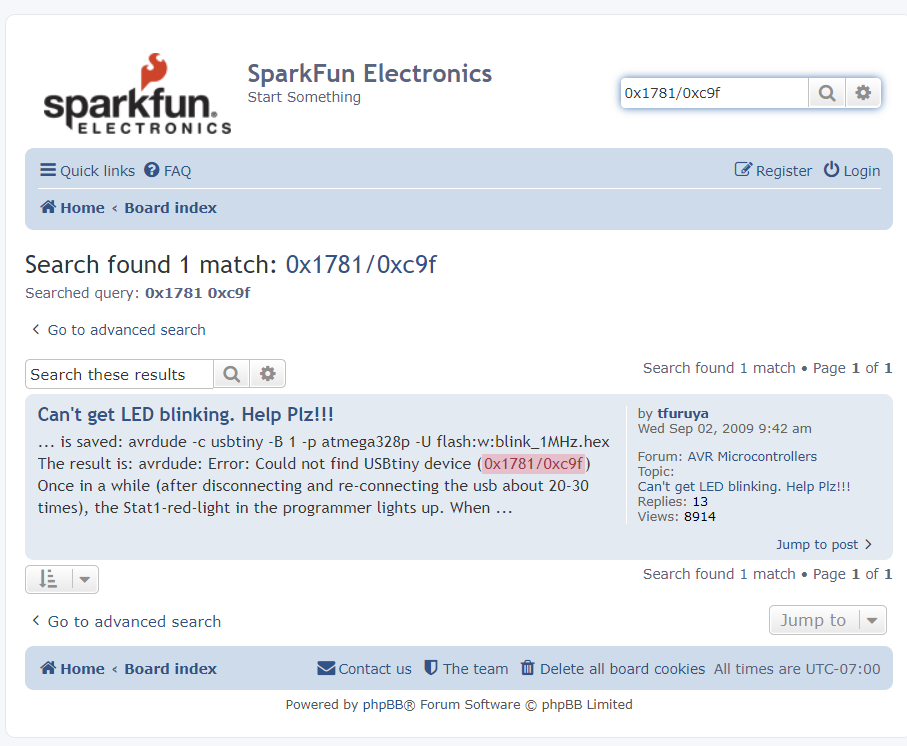
You will find people with the same problem, however i just searched and couldn't find a confirmation from the person asking questions that indeed a solution has helped, if you really can't fix this just remake another ISP board and follow the tutorials again, this is my tip for you as i myself don't know how it worked for me, it suddenly did and sometimes electronics do that, lots of factors are involved. The other one was very easy, something is wrong with your connections, it's either the connections to the board with cables, or the board itself has soldering issues, in my experience (found this in 3 boards) it was usually the boards. The Steps for solving the second error is by: 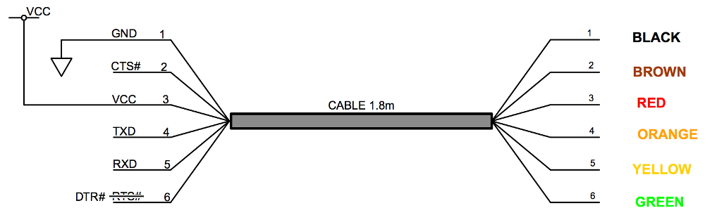
Also i had this issue which was big to me, as i kept forgetting to use the command "make program" and once i figured out that i missed that, i was done with my board. 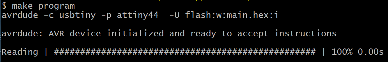
All i had to do left was take off the soldered bridge and the jumper(resistor 0). 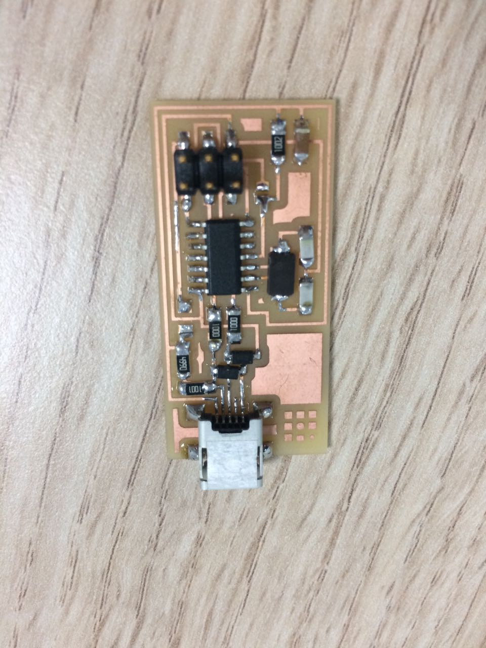
|
-Others
|
I learned how to make these ISP connector cables, feels so good to make one! The tutorial i followed is linked here. The original tutorial is by Anna Kaziunas France. It was updated by Eduardo Chamorro Seoul. |