Week11 - Input Devices
1-Ultrasonic Sensor
|
I chose to use the ultrasonic Sensor HC-SR04 for my Input Device week. This will help me with my final project because i am also planning on using this sensor as an input. 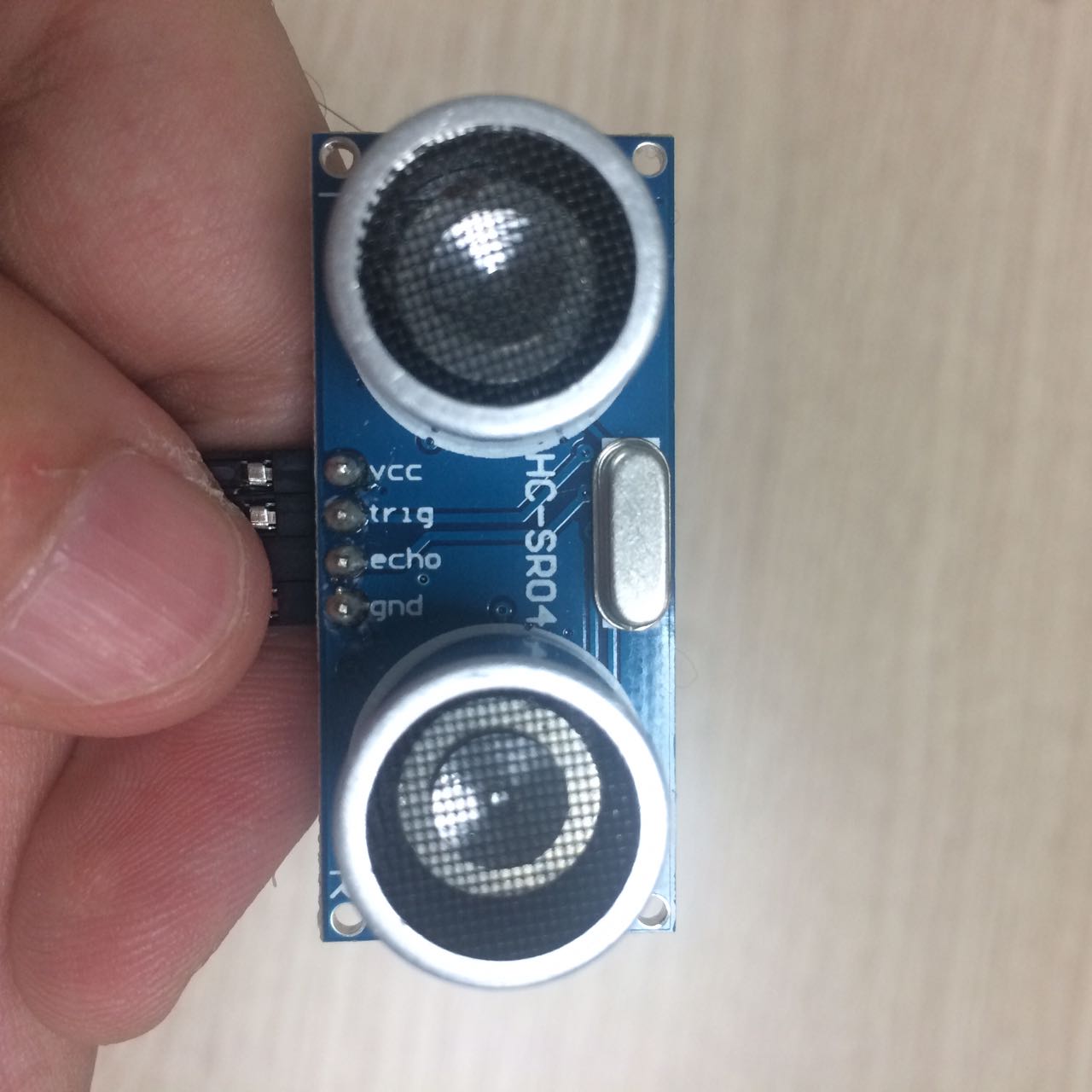
This sensor uses ultrasonic waves, meaning waves with higher frequencies than our human hearing ability limit. Eidha Al Rashdi actually discovered that you can hear it with your phone mic. WARNING LOUD NOISE!Ultrasonic can be used in Imaging, sonography and few other uses. I will use the most basic use, distance calculation. The ultrasonic actually transmit these high frequency waves which reflect on surfaces and to the sensor again, the sensor measures the time it took for the wave to transmit and then come back to the sensor, a mathematical formula transforms the time into a distance measurement. The sensor datasheet explains how the sensor operates, Trig is an input pin, so you can write to it, the Echo is an output pin, so you can read the output from that pin. 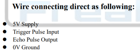
I actually understood that more clearly after i followed the arduino code in this tutorial, the code comments explain better than the datasheet in my opinion. Download Ino file here. I had to see how the ultrasonic works before i make anything, so i used an arduino and connected it to the ultrasonic. 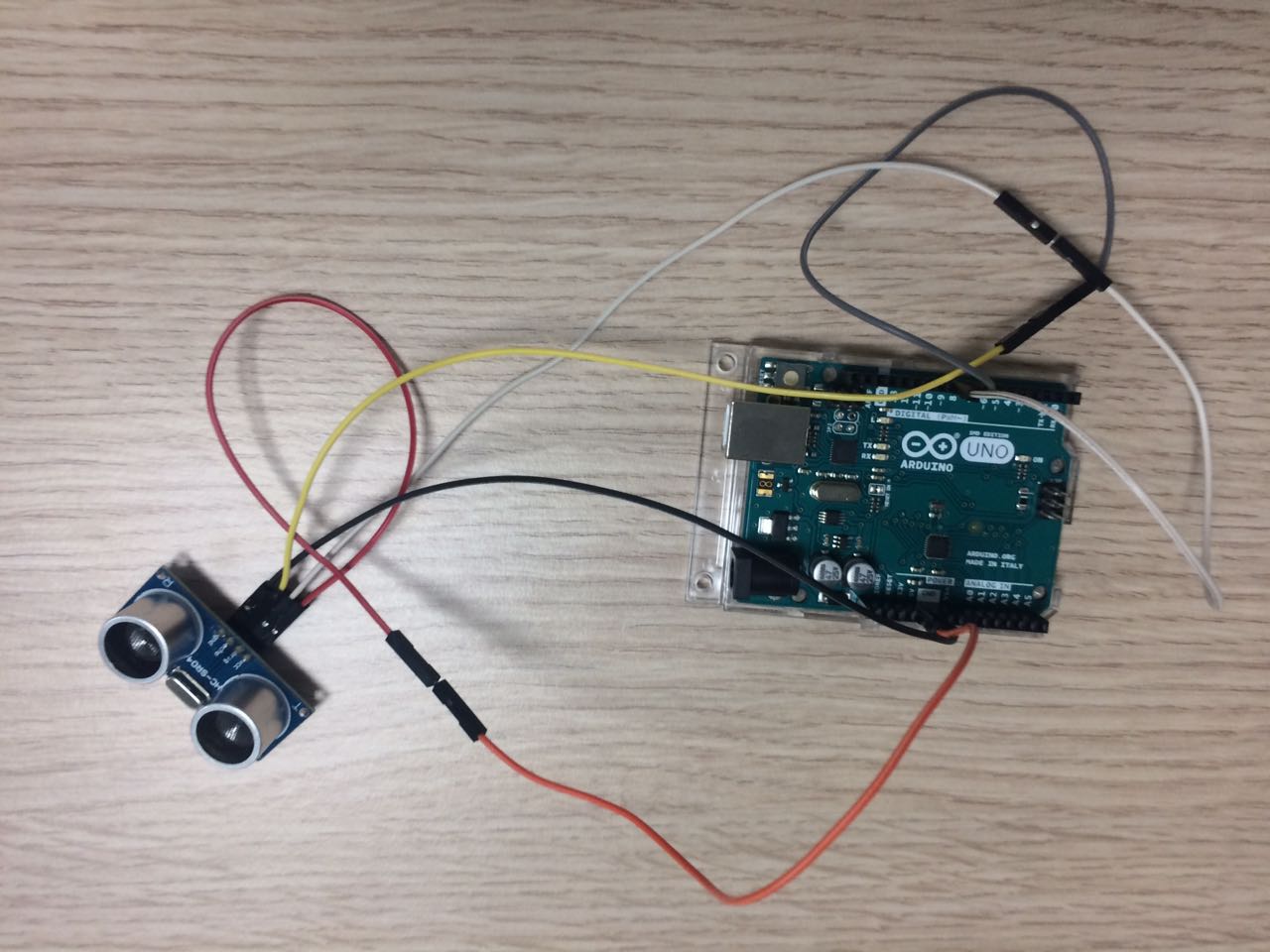
I just uploaded the code to the arduino and opened the serial monitor and started playing with the sensor. 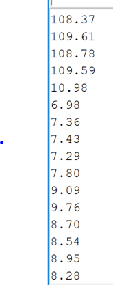
It works Perfectly! 2-Input BoardAfter i made it work with the arduino, i thought this is simple enough and i can do it. the datasheet didnt add any notes of components that had to be with the ultrasonic, so i improvised and thought this list is enough. 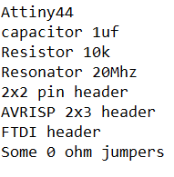
I worked on Eagle by Autodesk, I love this software, i really however hate the search of components to add, searching manually by reading is so much faster than the search tool sometimes. So i was done with the schematics and PCB design and connected everything together, doublechecked and all. 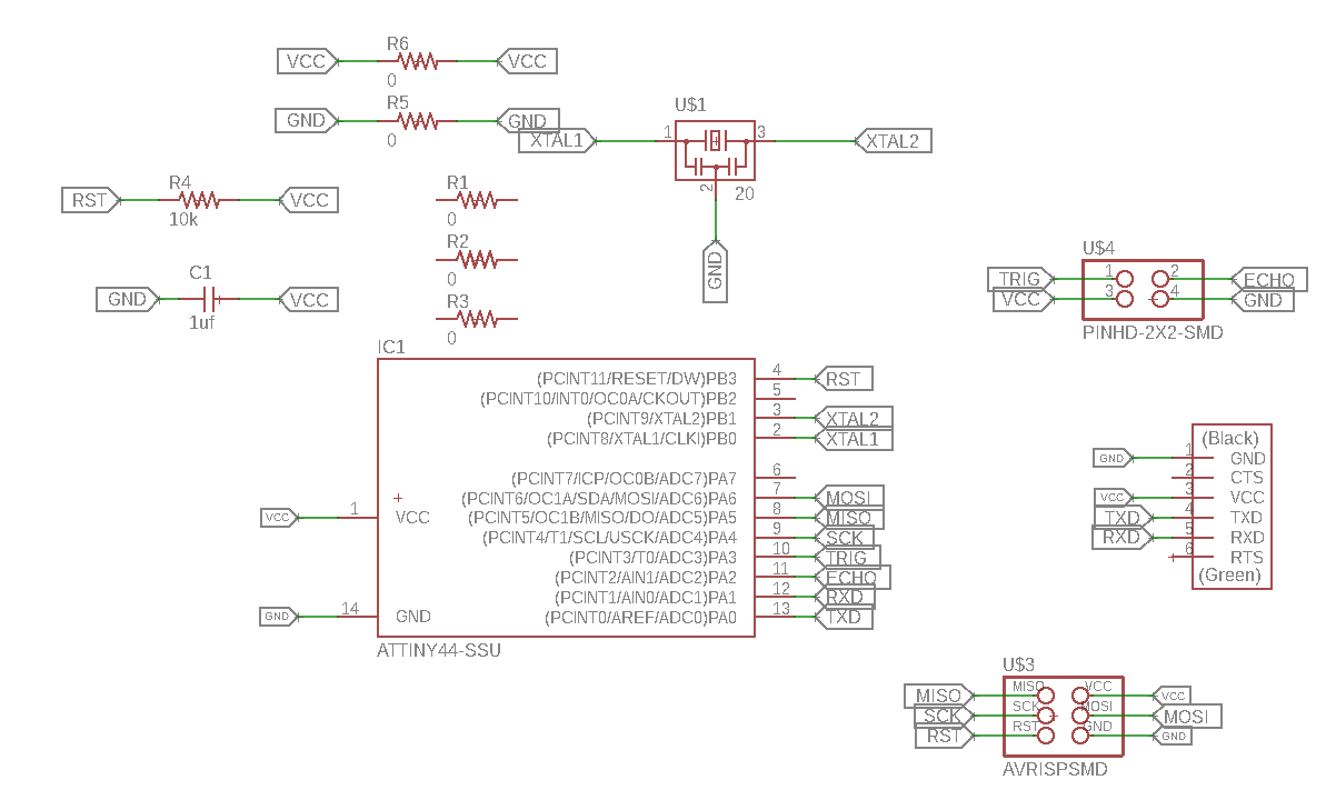
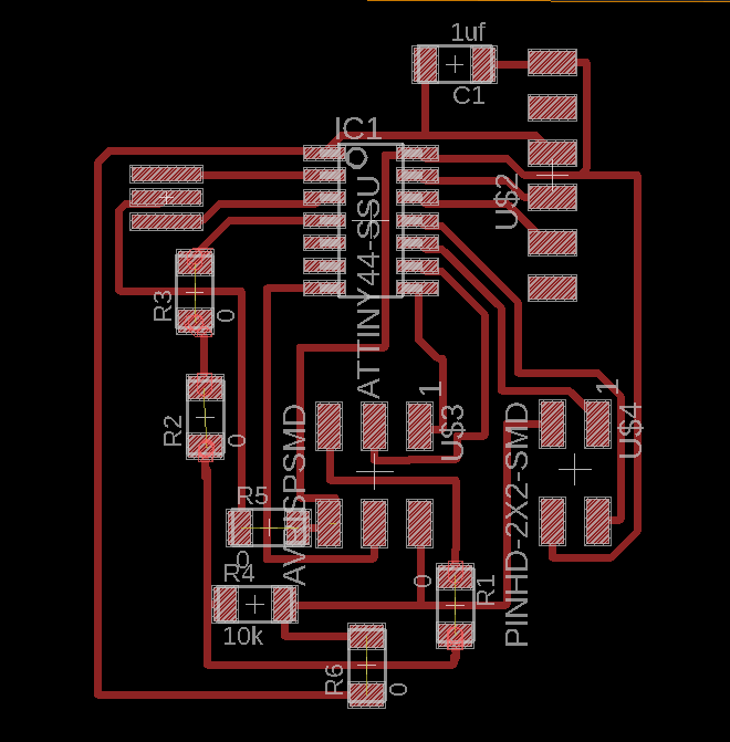
Let me talk about the PCB part, earlier than this week, i used to do the traces manually, which was a struggle. later on i thought there is no way that is how people do it, later i found this. 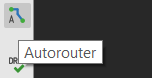
This tiny tool is used to automatically draw the traces for you! However it's not perfect, I would say it could actually be better. You see when you use it, sometimes you dont get 100% result, like what i got. 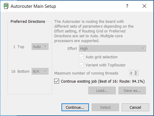
I got 94.1%, i chose that one, you actually get more results, but i chose that one because it is the easiest to patch and complete the job manually. That is what you get sometimes and this is the solution to it. If you want to get 100% all the time, you would need to enable the bottom direction as well, the softwawre will automatically drill holes so you can connect them under the board, so basically bottom jumpers, which will be perfect everytime, or at least they should be, i never tried it. Well now that i exported the board design to PNG. 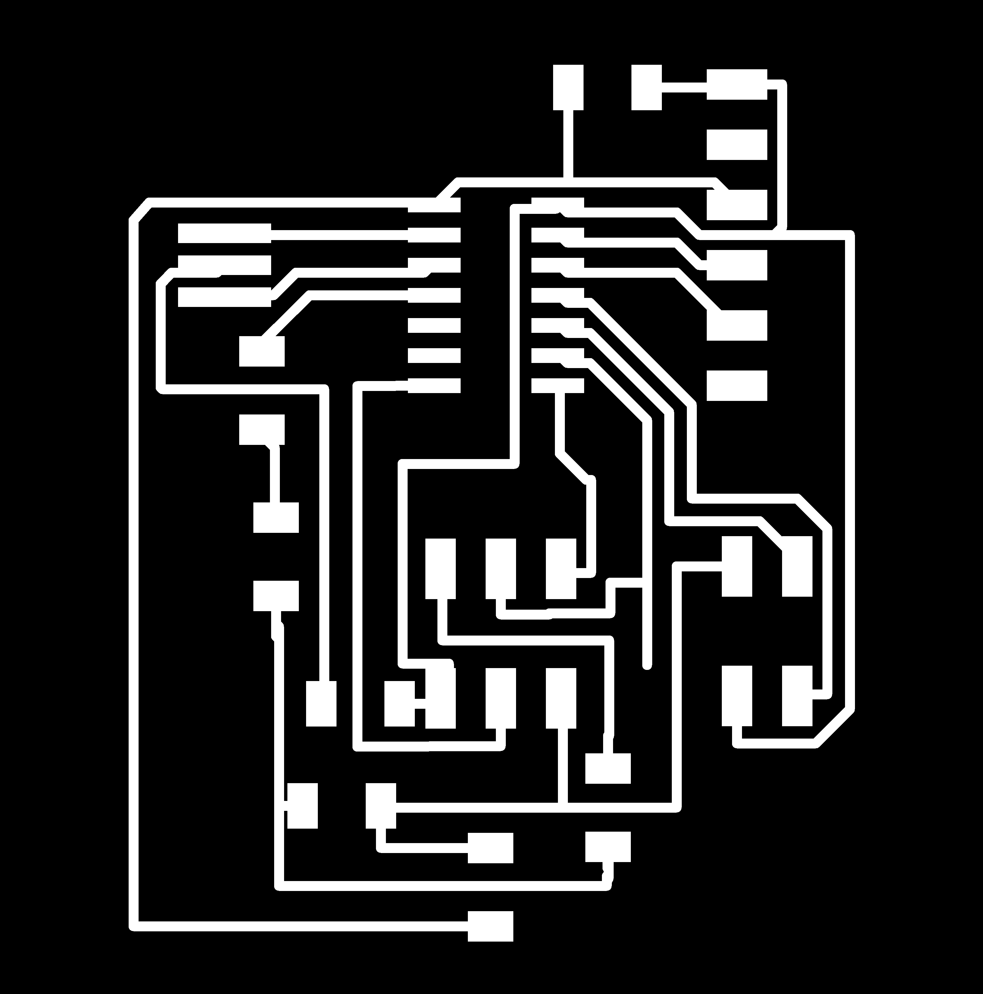
I went to FabModules and converted the PNG to an RML file with the right configurations for my milling machince which is the SRM-20. then did the tracing! The board is finally done. 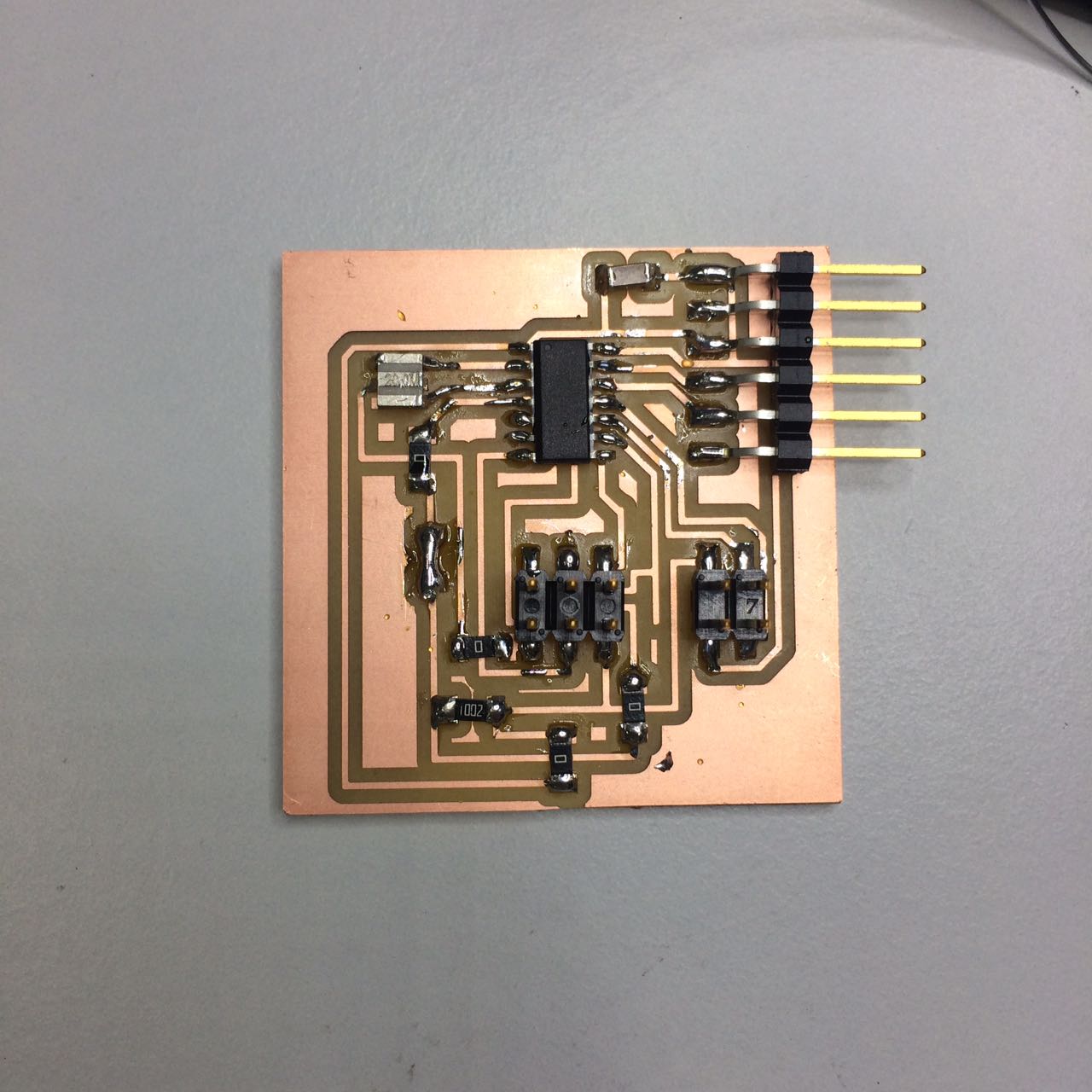
3-Programming boardI had the code already from the earlier tutorial. I saw the attiny datasheet and choose 2 pins as my echo and trigger pins for the schematics, and again to set up the pins in the arduino code. 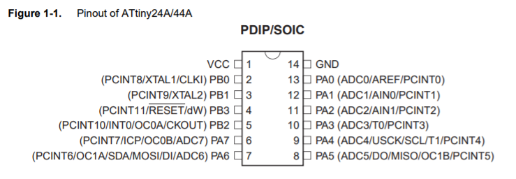
When i tried uploading i got a blank screen on the serial monitor. It took me hours to finally find out i forgot to burn the bootloader. I burned the bootloader to the board and uploaded the code. connected the sensor to the board and opened the serial monitor. 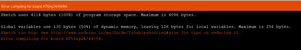
Sketch uses 4114 bytes of 4096, So close yet so far... I wasn't gonna create another board or switch the attiny44, which i should've done now that i think about it. i just wanted to see if it would work. so i deleted some lines in code. 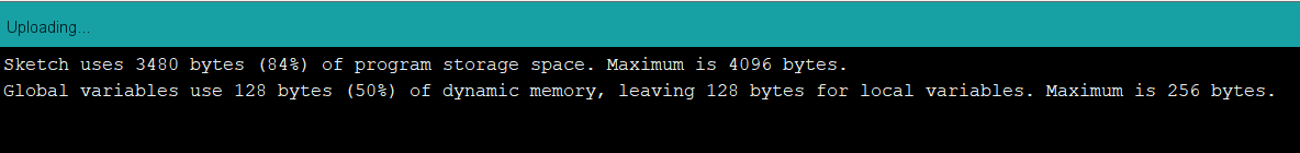
It was a fun process deleting lines of code and looking at how much difference that would make. I learned that having a float or double value on your code, can alone take upto 700 bytes. I believe my attiny wasn't damaged, the code would take that much storage space anyway, so I will try another attempt later with another board, because i need it for my final project, So check the project development page on Week20. Alright so i deleted the float number in the code, so that means no more correct distance numbers, but i would be able to see something right? Wrong.. 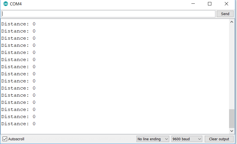
After Exausting most solutions on the same board, i saw something by touching the connections, apprently they were bad connections?! I tried soldering the connections and this is the result. 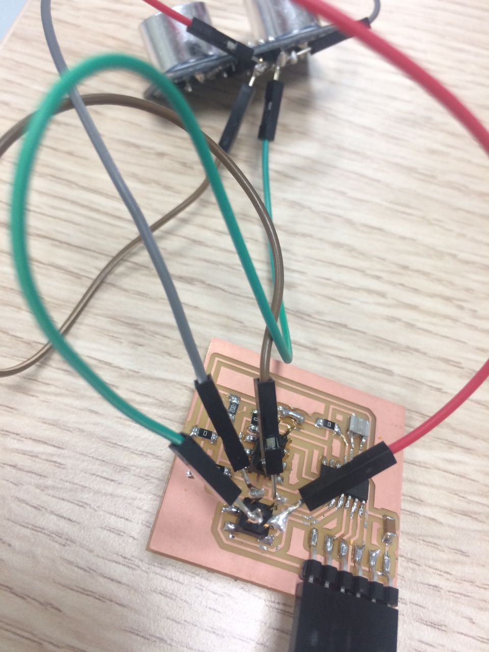
This actually worked! and i got a result that kept changing numbers when i moved my hand in front of the sensor. The result is just in numbers because i deleted the print line, due to the storage space issue. The "Distance: " is not in the uploaded code for the below image. 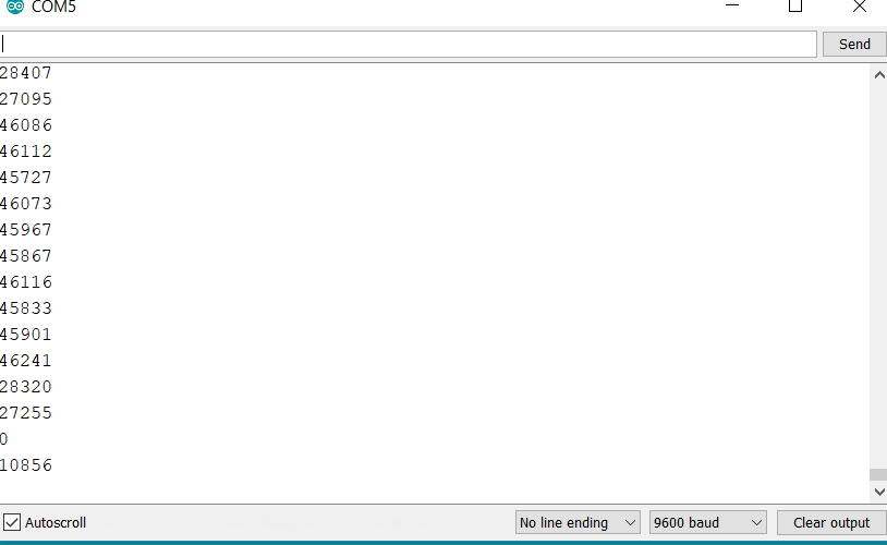
So it worked after struggle! I saved over the code I modified for this to work because of the size issue, but if i remmeber correctly this was the code. Download the edited software serial Ino file here, the deleted line is not commented in the file, I assume your Attiny44 will be just fine with this code to view on the serial monitor. So my code apprently takes more than what the attiny44 can hold, so i used attiny84 which can hold upto 8kb of storage space, although the schematics show 44, it is the exact same size and number of pins, so it doesnt matter that the schematic show 44. Link back to Week05 for the SRM20 setup and usage. |