DXB PLOTTER
SLIDE & video

Design Files
Download the design files HERE
DXB plotter - fablab uae
Mechanical & Machine Design
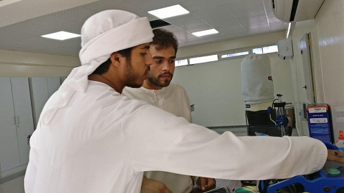
MAY 04 - MAY 18● We at Fablab UAE decided on making our own version of the XY Plotter machine and here is our documented report on how we made the idea into reality; what challenges we faced, how we overcame them, what applications it has in future and a presentation slide along with a video.
● It was a very healthy discussion we had to finalize the machine our group will be making in the next two weeks, to start with just the mechanical parts which will be moved using hands and then in the second week we digitize the machine.
machine idea
sketch & Planning
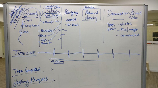
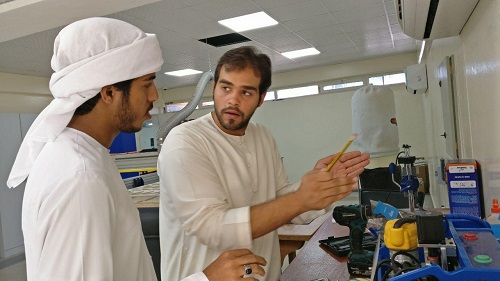
● The basic requirement was to design the machine that includes mechanism, actuation and automation. Also to build the mechanical parts and operate it manually.
● The group is really enjoying their time in the planning and dedicating utmost amount of time for this particular project because we all will be learning a lot of things from this 2 weeks particularly how to work in a group and share knowledge and experience with each other.
progress report
roles & responsibilities
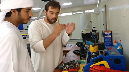
● The entire team also invested some of their time in doing some sort of research which could be a great deal of help for the next few days.
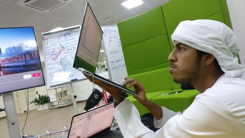
● Day 1, the entire team showcased a great amount of energy and enthusiasm, followed by some really informative brain stroming sessions to get more understanding for what we are doing and some clear idea of the next move.
● Our priority was to distribute the roles in such a way that each one of us has the opportunity to work on all the major departments to make sure everyone is on the same page and even if someone unfortunately is not able to come to the lab, we can proceed as per the plan and make sure the job is completed as planned.
ROLES :
● Zahrah & Zubair -
worked on 3d modeling for the pen holder and testing, prototyping the same on Ultimaker using PLA material.
● Salama and Eidha -
Worked on parametric and 2d design for modular motion box for the x-y axis. Also cutting the same using Universal laser cutter on 3mm & 6mm acrylic matetrial.
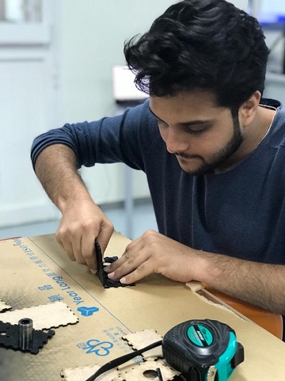
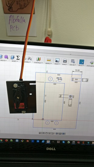
● Darshan & Abdulla -
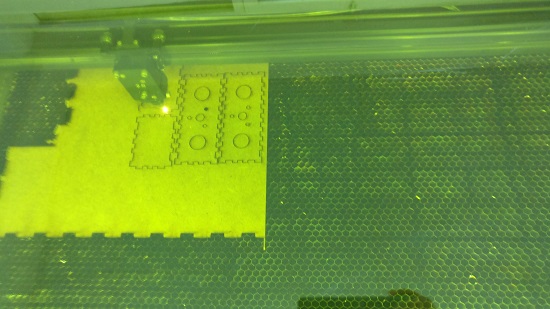
Worked on the body and choosing the right material and design, also looking after the dimensions which will be shared with other group members as well to keep in consideration. Tested the body using 3mm MDF material on the Universal laser cutter.
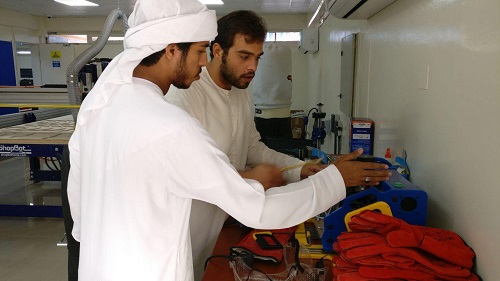
● After the first couple of days we change our roles in order to take part in each of the aspects of the machine building and also because not all of the group members were present in the lab at the same time because of their personal commitments, so in order to run the show, everyone showed their ultimate potential and character to work at their best while they were present.
challenges & solutions
troubleshooting
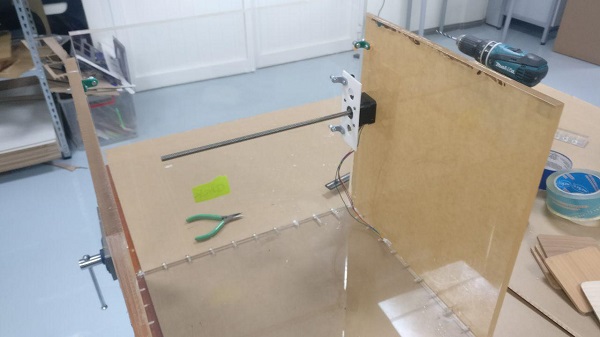
● The idea was to make it strong, sturdy and alligned at the same time, so the idea behind using MDF was only limited to testing the design and then moving on to different material and altering the design a bit.
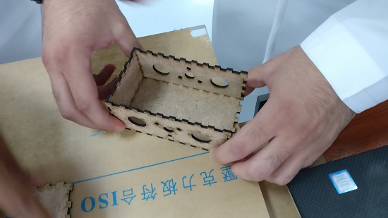
● Then, we started testing the body on 12mm Acrylic, so that it would be really strong based on our design and it would also make it look nice. The first test we did, we did not design the slots, because of which we had to use a lot screws in order to attach the different parts of the body to one another.


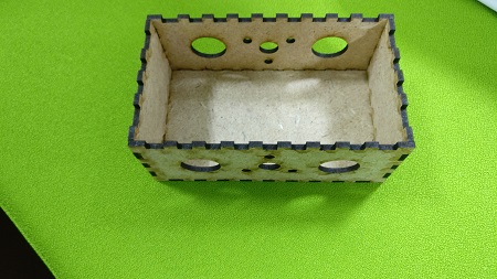
● We invested some time into this act and realized that this is not going to helpful in terms of the alignment and the looks of the machine as well, we used way lot screws and none of them really helped, but thats fine because we learned something of real importance of what we should not do and moved on to design the body in such way that we used minimum screws and more slots in order to achieve what we wished for.
● Another challenge we faced was that we had a rather disappointing time with couple of laser cutters available at our lab, due to some technical issues in the focus of the laser, the universal laser system could not cut the materials. So that was a little bit of a disappointment considering the time we were facing. We have 2 Universal Laser machine and the big machine had some technical problem, so we started using the small machine, but we realized that there was some issue with this machine as well.
● Firstly, it did not cut in the straight vertical direction, the cuts for holes and slots were all inclned and also, we somehow could not find the right kerf even though we tried the same kerf and in one test it would fit fine and the other time it was very loose. So this was an interesting challenge, so got introduced to a new laser cutter which was the Trotec machine, and it has been a rather exciting experience to get a chance to work on this machine as well. This machine in particular performed brilliantly compared to what we faced with other machines.
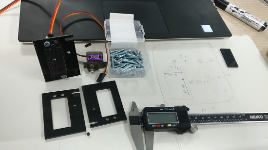
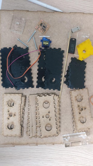
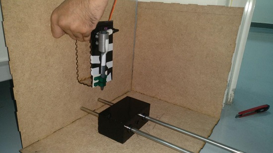
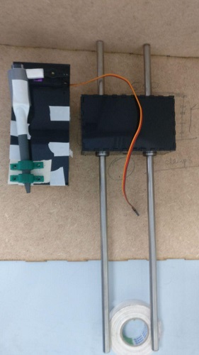
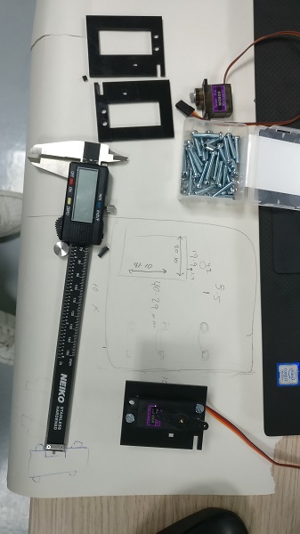
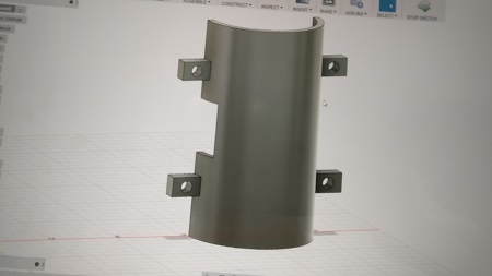
● Also the other important component of our design and prototype was to make the moving x axis which also has the pen holder which will be the actual end application of the xy plotter, to draw something using some sort of a pen. In order to make sure the pen is perfectly holded during those movements we had to design something whoch holds it tight enough.
● The idea of the pen was to only move with the modular motion box in the x axis, so the other concern was how to lift the pen off the bed when it is moving from one point to another or whenb its not in use. To achieve the same we focused on using a servo motor, with its little movement in, we could lift the pen of the bed accordingly, so again we had to design the pen holder in such a way that it is connected to the servo motor somehows so when the servo moves then pen would move graudually in the z axis.
bill of materials
tools and techniques
● Following are the materials, techniques, technologies and softwares we used:
● 3mm MDF
●6mm Acrylic
●PLA
●12mm Acrylic
●Vernier Calliper
●Drilling Machine
●Ultimaker 3d Printer
●Universal Laser Machines
●Trotec Laser Machine
●Servo Motor
●Guide rods
●Various sizes of Pens
●Screws and Nuts
●Measuring Tapes and Ruler
●Screw
●Drivers Hammers
●Fusion 360
●Cura
●Corel Draw
● Lots of motivation and confidence
Machine Design
Week 02 Progress
We design and build a machine that plots almost anything.
“DXB Plotter”
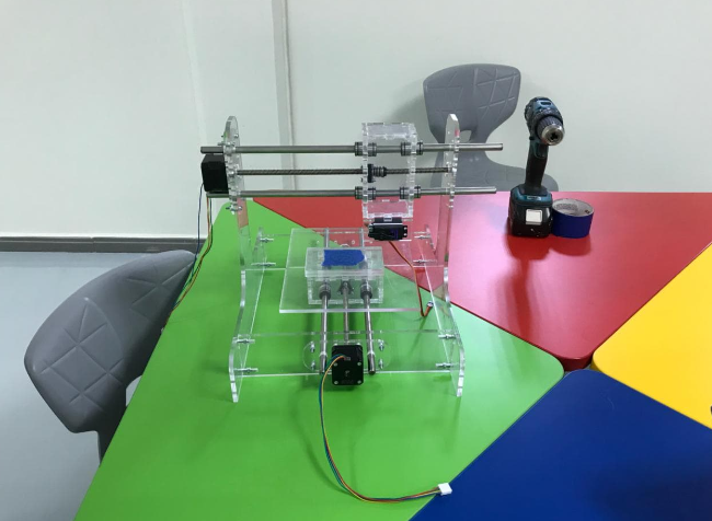
Before we begin to talk about our specific part in the project, we think it's important to see the first part of the project successful and done to move on the part of working the machine. Well, the concept was already clear in our heads and even if we had the main files to build the axes, it was hard to figure the way it would move or space it'd take. Especially in the coming part which is calculating the steps the motor moves or runs in such distance “1 mm”. Muaath and Hashim explained the formula of calculating that.
Back to the idea of out project “DXB Plotter”, It's sure that the concept is not the most innovative in the way that it does already exist and that we probably did not push the concept that far upfront. Still, for us, at least, it's a bold move to machines building and the result seemed really awesome to us!! As a reminder, we are still novice and we've already traveled a long way to arrive at that point where we could make such a machine!
Planning
Also, as a group assignment for this phase of the project here how we separated the tasks:
- Servo motor ( Eidha)
- Stepper ( Darshan)
- Limit switch ( Zubair)
- XY Axis movement ( Salama)
- Video, poster and vinyl (Zahrah )
Calculation
We had to calculate how many steps per 1 millimeter. we need to specify an axis’ steps per mm that means how many steps the motor has to run to reach a motion of 1 mm.
We used this page for calculation (http://www.aquickcnc.com/wiki/Stepper_Motor_Calculations)
A very common resolution for stepper motors is 200 steps per revolution, so we know 200(steps per revolution).
It's hard to measure turns per 1 mm so what we measure the distance in one turn and quarter (1.25 revolution) and it was 9.17(mm).
200(steps) *1.25 (revolution) = 250 (steps) then we found steps per 1mm by dividing the steps by distance 250(steps)/9.17(mm) = 27.26(steps per 1mm).
Typical stepper motors are 1.8 (degrees per step) this will increase the accuracy and smooth the movement of the motor beside reducing the noise, so we enable something called micro stepping. This will increase the number of steps per revolution with a factor of 2n (n is an integer).
so we multiply steps per mm by micro-stepping settings 8*27.26(steps per 1mm)= 218 (steps per 1mm).
We have to provide this number (218 steps per 1mm) to the software for motion control.
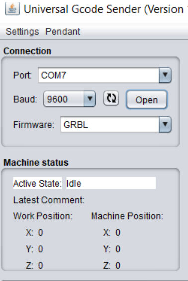
In the universal G-code sender we have to identify which com port we are using to communicate with our machine. we are selecting the firmware should be set to GRBL and the baud rate that corresponds to our machine. The baud rate should be similar to the baud rate to what we had in Arduino IDE.
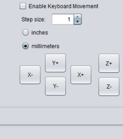
There is an keyboard movement option with step size and unit. This will control the axis manually.
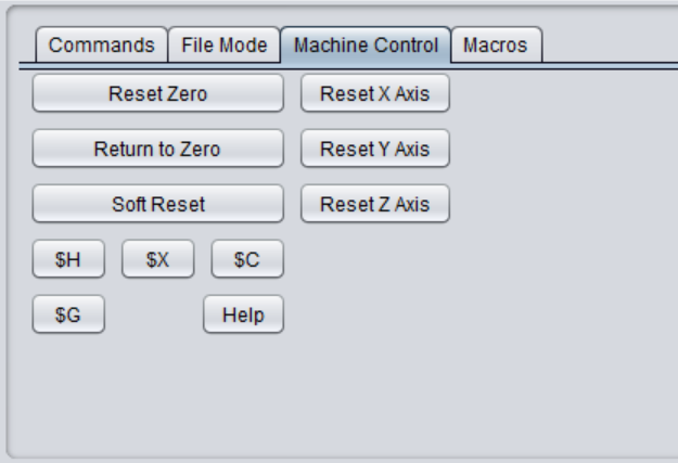
After we sit X and Y axis in a proper position we set the machine zero location by click on Reset Zero that means that we initialize the home position for our machine.
We wrote $$ in the command bar that will display the settings for the movement for each axis. Update the GRBL settings by typing the following into the command line.
$0 = 218 this command then press enter for X axis
$1 = 218 this command then press enter for Y axis

Alzubair Part
-Limit Switches
We worked on a limit switch called KW12.
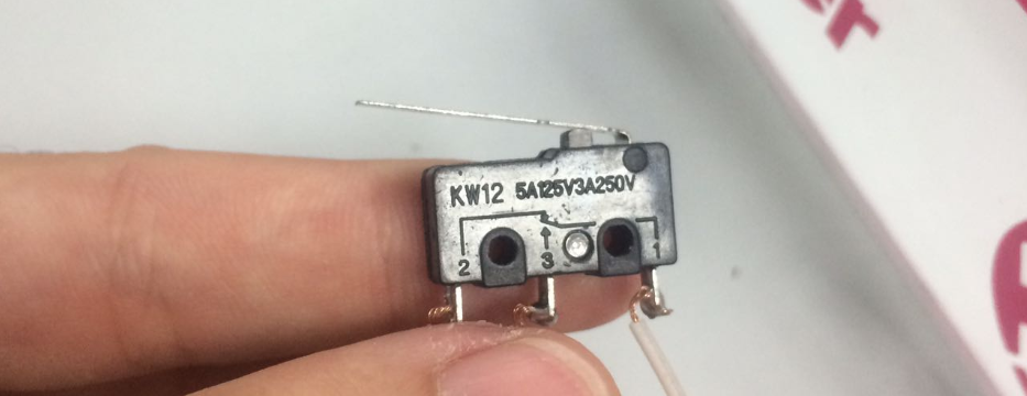
The connections were easy, C,NO that's all we needed as we connected to the CNC Shield. The white goes with the C, which is where the electricity goes, the NO is where the circle closes when the switch clicks.
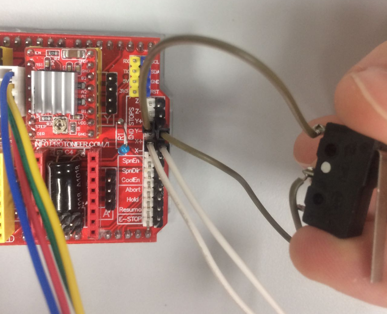
After that the only thing missing is to enable the homing cycle and the hard limits, and they are $17 and $16, we need to set them to 1 which means true as in enabled. Then they work perfectly with the limit switches.
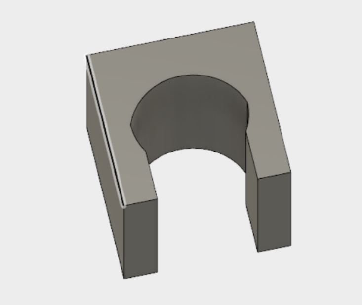
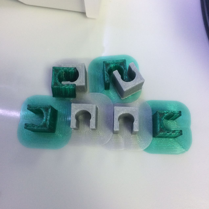
- Clippers for Wiring For the wiring, we tried something really simple with relation to the thickness of our base material, which is almost 6mm, and we got the shape below, after a second attempt in a similar design, we basically just made the space wider by 1mm more than the first design. That was it.
-Universal G-code Sender
We had problems with sending files with the G-code, it didn't work before. We fixed that by changing some settings for the drawing we have from inkscape, because that's what we used. First thing was making the drawing Hairline.
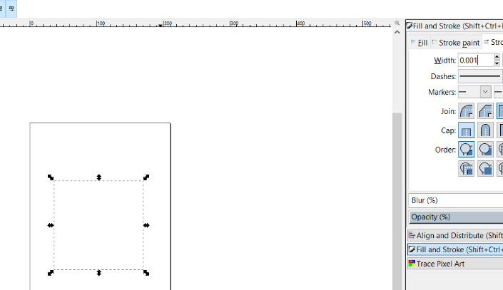
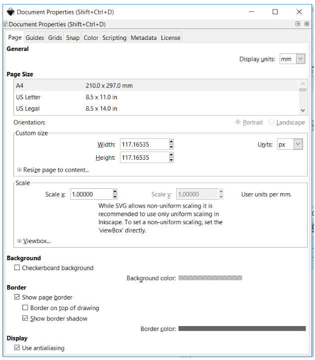
Second is changing the canvas size so that it fits the shape we have. And also make sure its in px like the picture below.
Then we just saved it but we did change settings when we get the G-code Window, as we didnt have a stepper Z-Axis, we changed most values that depended on it to zero.

● Indexers
● The indexer (or controller) is a microprocessor capable of generating step pulses and direction signals for the driver. In addition, the indexer is typically required to perform many other sophisticated command functions.
Drivers
● The driver (or amplifier) converts the indexer command signals into the power necessary to energize the motor windings. There are numerous types of drivers, with different voltage and current ratings and construction technology. Not all drivers are suitable to run all motors, so when designing a motion control system the driver selection process is critical.
● CNC Shield Board:
● Latest CNC Shield Version 3.0 for Arduino.
● GRBL 0.9 compatible. (Open source firmware that runs on an UNO for Arduino that turns G-code commands into stepper signals)
● PWM Spindle and direction pins
● 4-Axis support (X, Y, Z , A-Can duplicate X,Y,Z or do a full 4th axis with custom firmware using pins D12 and D13)
● 2 x End stops for each axis (6 in total)
● Coolant enable
● Uses removable A4988 or DRV8825 compatible stepper drivers
● Jumpers to set the Micro-Stepping for the stepper drivers. (Some drivers like the DRV8825 can do up to 1/32 micro-stepping )
● Compact design.
● Stepper Motors can be connected with 4 pin molex connectors or soldered in place.
● Runs on 12-36V DC.
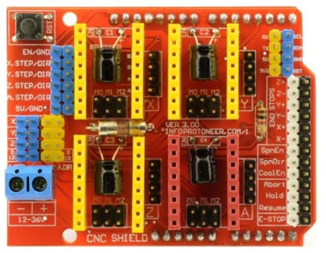
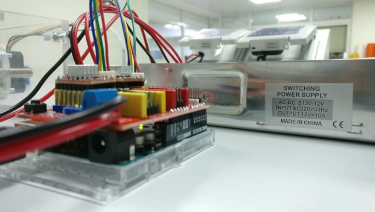
Image has been downloaded from this LINK
● In order to communicate with the stepper motor, using arduino we download the following essential tools, softwares and extensions.
● Grbl is a free, open source, high performance software for controlling the motion of machines that move, that make things, or that make things move, and will run on a straight Arduino.
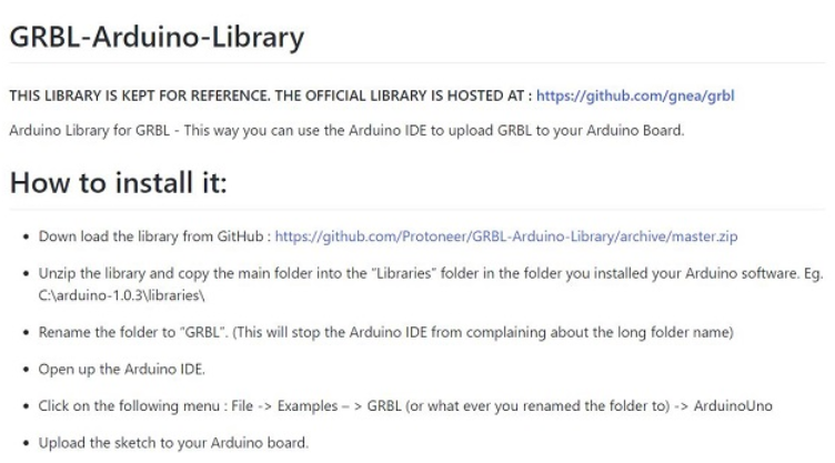
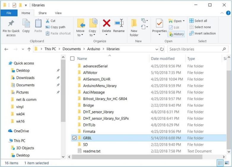
● This is the LINK to download GRBL library for arduino
●Grbl Controller is software that is designed to send GCode to CNC machines, such as 3D milling machines. It isn't super smart, it just needs to give the user a nice way to get commands down to whatever controller they are using. Version 3.0 is has been optimized for the Arduino to control Grbl shields.
● Inorder to copy the GRBL files, we first extract all file and choose the folder inide the main downlaoded folder and copy the same to the Arduino libraries as show in the image below.
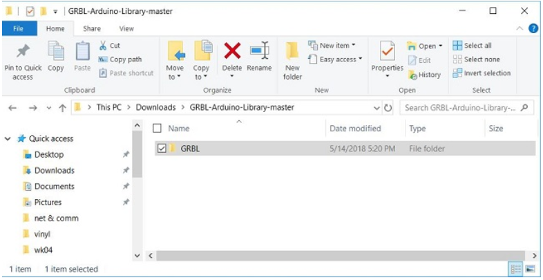

Image has been used from this LINK
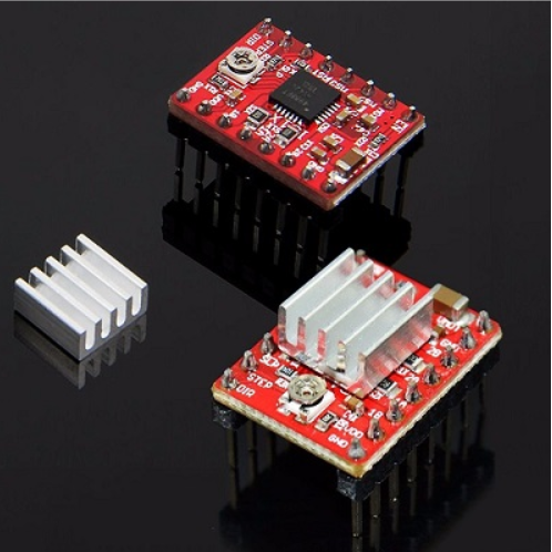
CNC Shield Board: Package Includes:
●1 x CNC Shield Board
●4 x A4988 Stepper Motor Driver
●4 x Heat Sink
● Since we are using only 2 stepper motor for, the following image shows the connection of the same with the drivers on shield.
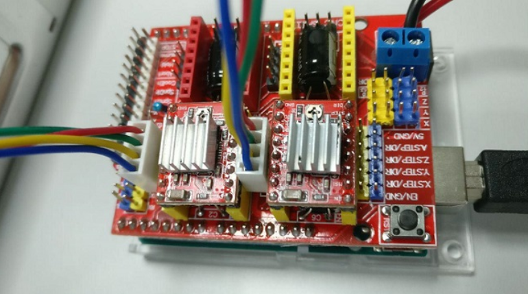
● Also the stepper requires power of 12V, so we connected an external power supply to the shield as well.
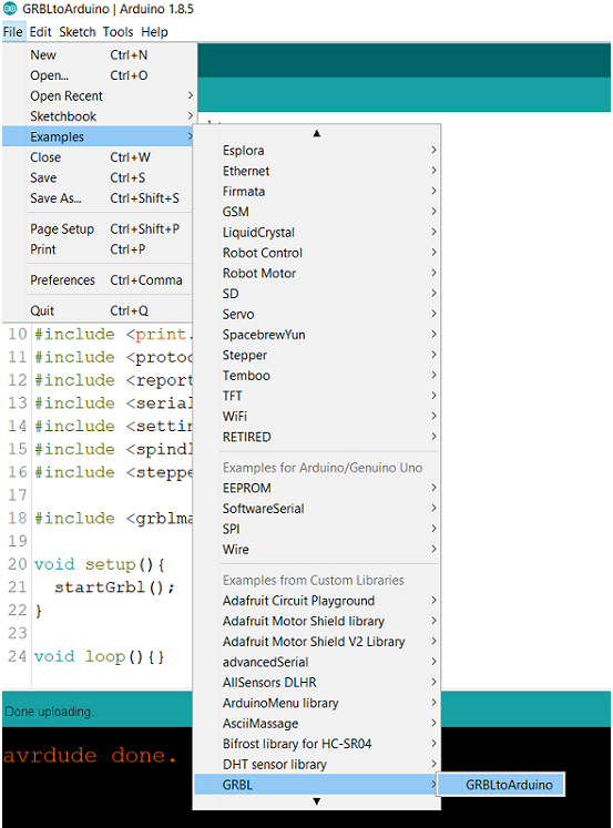
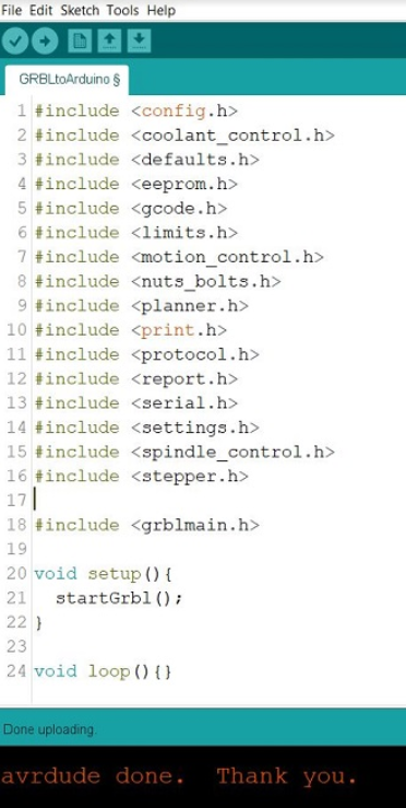
● We choose the example option and open the GRBL/ GRBL to Arduino to obtain the code.
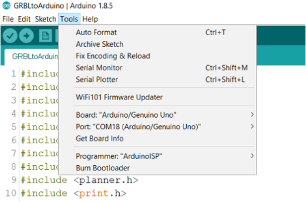
● The following image shows that I selected the Arduino Uno board and ArduinoISP to upload the sketch.
● The following is the code, from the GRBL to Arduino library, used to program the arduino wiht sheild in order to communicate with the motors through GRBL and universal gcode sender.
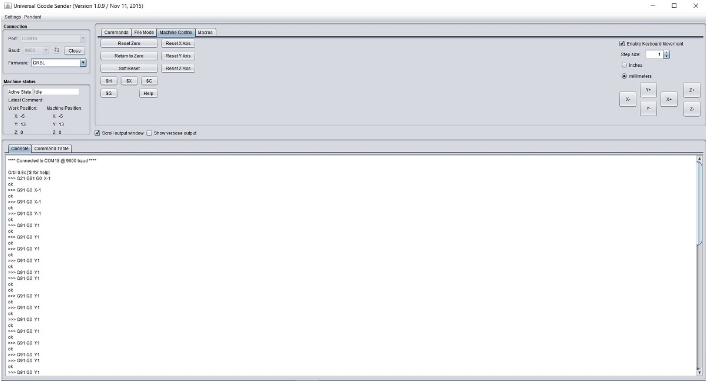
● This is the LINK to download Universal G code sender software.
● This is how the software look like once connected to the port and using firmware GRBL to communicate with the stepper motors.
● Here we can choose options such as command and edit them as per the stepper motor and project requirement, also control the motors with the help of machine control.
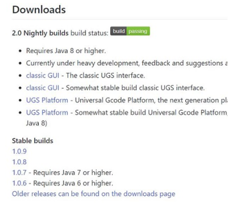
● We need to have a java script to run the above software. This is the LINK to download Java script to run the universal gcode sender software.
● G-codes, also called preparatory codes, are any word in a CNC program that begins with the letter G. Generally it is a code telling the machine tool what type of action to perform, such as: Rapid movement (transport the tool as quickly as possible in between cuts)
● This is the LINK to download extension for gcode in inkscape.
● Driving Stepper Step in time, step in time Come on, mateys, step in time Step in time Step in time, step in time Step in time, step in time Never need a reason, never need a rhyme We step in time, we step in time "Step In Time" Robert B. Sherman and Richard M. Sherman
● The following image shows the poster we have been preparing for our group project page, as per the specifications of 1920x1080. Its been quite a good progress in terms of the testing and integration part of the project. The group showed great amount of passion to achieve the results in the given time.
FUTURE OPPORTUNITIES
implications & applications
● In future to make the machine more accurate and better in the looks we shall use the HDPE material and design the main body in the way that slots would be the only thing needed to make it stand and HDPE would be really strong and better alligned.
● For the moment we actually don't know much about the future modifications of the product but by the end of week 2, we shall definitely have more idea what additions we add in future to achieve higher output.
● Also a wireless controll through some app would be a quite good addition if we could be able to do it.