FINAL PROJECT
This videos show how the program and its board work along with the web cam, the laser beam, the motor, the mirror and the reflectors.
My journey through Fab Academy has been great. It has definitely not been easy, but I have learned a lot. I began without any knowledge of electronics, or anything related to digital fabrication. It is an amazing world and there is still a lot for me to learn and to practice.
This final project pretty much reflects what I have lived and learned through this six months. You will see how I see design, what things I can do good and which others I still need to practice a lot. I really appreciate all the support I ave had from both my global as local instructors who not only guided me through the process and thought me , but who also inspired me i to create, to learned, to be better and to share with other the knowledge that has been created in a clear and helpful way.
I hope this page help anyone who needs it, and in case I can be helpful, please do not hesitate in contacting me I would love to talk about this or any other project. And learn from one another.
I want my project to help anyone who needs to learn that one can develop with motivation and determination. I want people to see the possibilities of digital manufacturing and inspire other women to participate in the Fab Academy as it is the key to professional and personal development that allows us to grow and excel.
I want my project to help anyone who needs to learn that one can develop with motivation and determination. I want people to see the possibilities of digital manufacturing and inspire other women to participate in the Fab Academy as it is the key to professional and personal development that allows us to grow and excel.
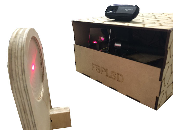
Ok, so lets begin (lets go a bit back to the videos above). In the left video it is a bit difficult to see the laser light in the reflectors because the laser used had a dim light but if you watch carefully you can see it change from the left to the right depending where I place a car for the web cam to detect. The light is also hard to see because I wasn't able to reflect the light directly inside the reflector (I had trouble with that precision due to the motors, theres more information about it below). Thats why the project need reflectors, and when the light hits right inside the reflector then it can be seen, otherwise you just see a spot near the reflector.
On the other hand, in the right video you can appreciate how the laser light hits the center of the reflector and the light is way brighter than in the left video (in this case I used a more potent laser.) You can also see how the Raspberry detects via the web cam where there is a car parked this can be seen in the monitor. When a car is parked in parking space 2 the program writes a 1 and vice-versa. So if there is a car parked in spot 2 then spot 1 is free and the laser light is reflected in spot 1.
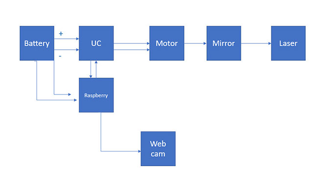
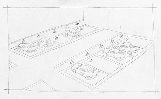
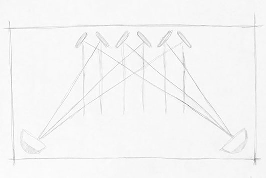
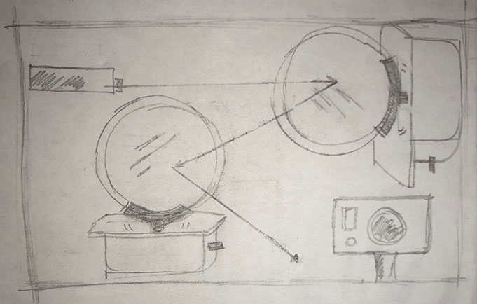
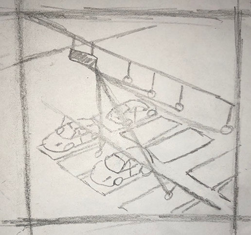
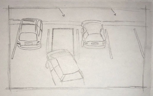
Here is a simple Layout explanation, I made it to help myself (and anyone who sees it ) to understand how the device works.:
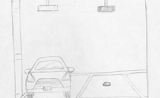
I started to draw my first draft regarding my final project. At the beginning I didn't know what or how it would look like. I just knew what I wanted it to do, help people find parking spaces and make that part of their life easier. It will also (hopefully) reduce contamination, because the cars wont be as long running while looking for a place to park. At the beginning I thought "It will be a device that allows you know if a parking space is available or not. Usually a person can see a red or green light that tells the driver if there's a free space, in this case either there is a light or there isn't. If there is a light shining above the parking space then the space is available, if there is n light then the spot is occupied by another car. The light shines because it reflects the light, if a car is parked then the driver won't be able to see the light, and therefore the spot would be occupied. I haven't figured out yet how the system will work, because it will not be made with electric cables,although it will definitely include electronic devices."
So, the idea is to reflect the light and use as little energy as possible. That lowers costs regarding energy, maintenance and infrastructure.

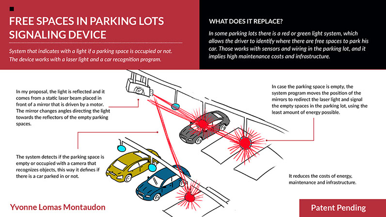
The project has changed a bit over time, what I want to show if there is a free space in the parking lot by showing a light above that parking space. There will be a camera that detects where there is or there isn't a car. And it will send a signal to a mirror moved by a servo motor to only direct a laser light to the parking space that is free.
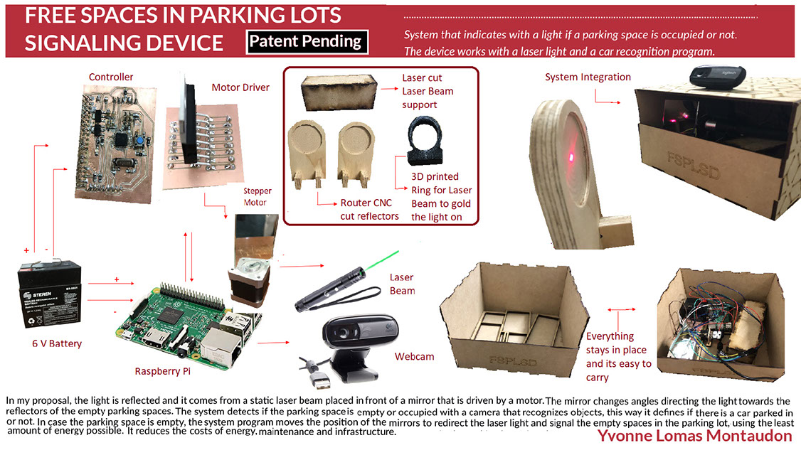
The proposed system indicates with a light on or off if a parking space is occupied or not. The reflected light comes from a static laser beam placed before a mirror driven by a motor. The mirror changes angle, directing the light towards the reflector of the empty drawers (all drawers have a reflector). The system detects if the parking space is empty or occupied by means of a camera that recognizes objects. It should be mentioned that the mirror moves at high speed so that movement is almost imperceptible, and the user only manages to see if there is a light on the parking space or not.
I used the next two videos as inspiration for the project.
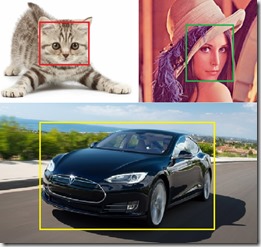
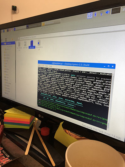
I used a car detection system, to get started. I used OpenCV to train the program of my final project in the detection of objects, in this case cars. The tutorial used can be found at the end of this page. OpenCV has several classifiers for the detection of faces, plates of cars, animals, cars and other things. In case you want to detect another type of OpenVC object, you can train our own classifiers to detect, for example, a specific animal.
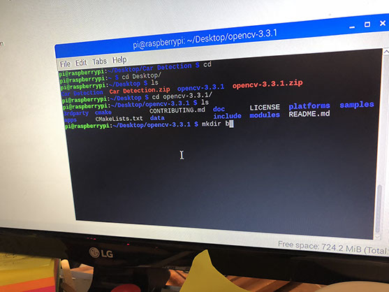
In OpenCV you can find the necessary executables to perform the training work in a simple way, the first one prepares the set of positive images and the other generates the cascade classifier. It is necessary to collect the set of images. Create the set of positive images with several images with the object that we want to detect and the negative one with images that do not contain the object. I used the Datasets for Computer Vision Research where there are many image databases that I can use to train OpenCV, we will select the images to detect UIUC Image Database for Car Detection. The first thing we will do is open CMD and run with the command:
cd C: \ opencv \ build \ x86 \ vc11 \ bin I moved to the folder that contains the applications opencv_createsamples.exe and opencv_traincascade.exe.
I used the following command to create the binary file cars.vec corresponding to the positive images, I used the application opencv_createsamples.exe I also require the folder with the positive images, we will call it pos, besides the text file cars.info that tells where to locate them . Once I have the binary cars.vec I proceed to create the cascade.xml this time I use the opencv_traincascade.exe application, I also need the neg.info file and the neg folder with the negative images. Then the code is used to load the classifier that was created. It is only necessary to change the .xml classifier and to detect cars with the webcam.

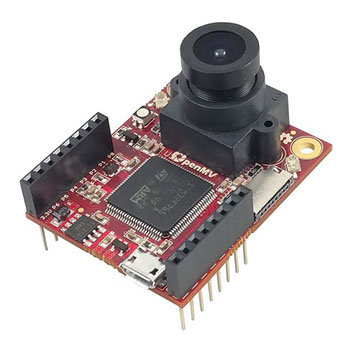
Sparkfun: Open MV M7 camera (65$)
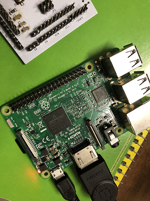
Mauser: Raspberry Pi 3 Model B+ ($40)
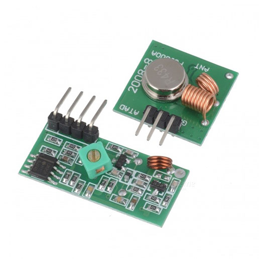
Japo Electrónica: two phenolic plaques, receptor and transmissior Modul RF 433 MHZ ($30)
Steren: two Motor Stepper NEMA 17, L928 Modul Driver, wo rechargeable lead acid 6 batteries, a lase light pointer ($65)
Fab Lab Puebla: ins, button, two 10k resistors, three 220 resistors, 3 Leds, one VREG 5V, one VREG 3.3V, Atmega328, 16MHz, six capacitors, two 22pf, jumpers, MDF.
This video was found in the Internet, and then with the program the computer could identify the cars by drawing a green rectangle around the,
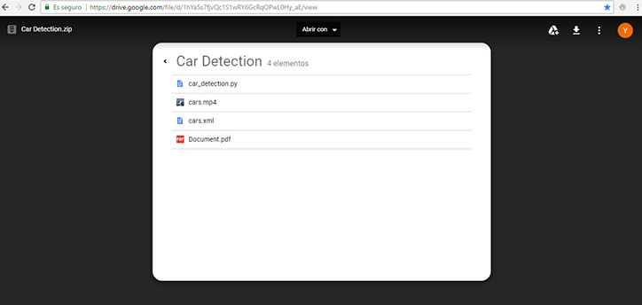
This is the folder with the files needed for Raspberry Pi for a smart camera. it can be found in the link at the bottom of this page.
I had to run a couple experiments first with Raspberry Pi with OpenCV and integrate it with the camera. The camera detects all the cars that are present in the place where the camera is set. It is important to note that the detection accuracy depends on the resolution of the image.
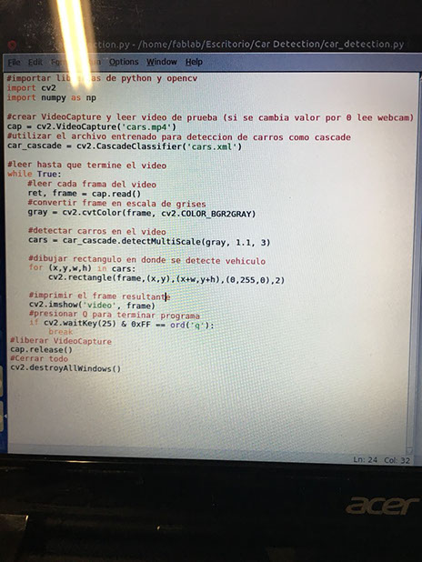
#importar librerias de python y opencv
import cv2
import numpy as np
#crear VideoCapture y leer video de prueba (si se cambia valor por 0 lee webcam)
cap = cv2.VideoCapture('cars.mp4')
#utilizar el archivo entrenado para deteccion de carros como cascade
car_cascade = cv2.CascadeClassifier('cars.xml')
#leer hasta que termine el video
while True:
#leer cada frama del video
ret, frame = cap.read()
#convertir frame en escala de grises
gray = cv2.cvtColor(frame, cv2.COLOR_BGR2GRAY)
#detectar carros en el video
cars = car_cascade.detectMultiScale(gray, 1.1, 3)
#dibujar rectangulo en donde se detecte vehiculo
for (x,y,w,h) in cars:
cv2.rectangle(frame,(x,y),(x+w,y+h),(0,255,0),2)
#imprimir el frame resultante
cv2.imshow('video', frame)
#presionar Q para terminar programa
if cv2.waitKey(25) & 0xFF == ord('q'):
break
#liberar VideoCapture
cap.release()
#Cerrar todo
cv2.destroyAllWindows()
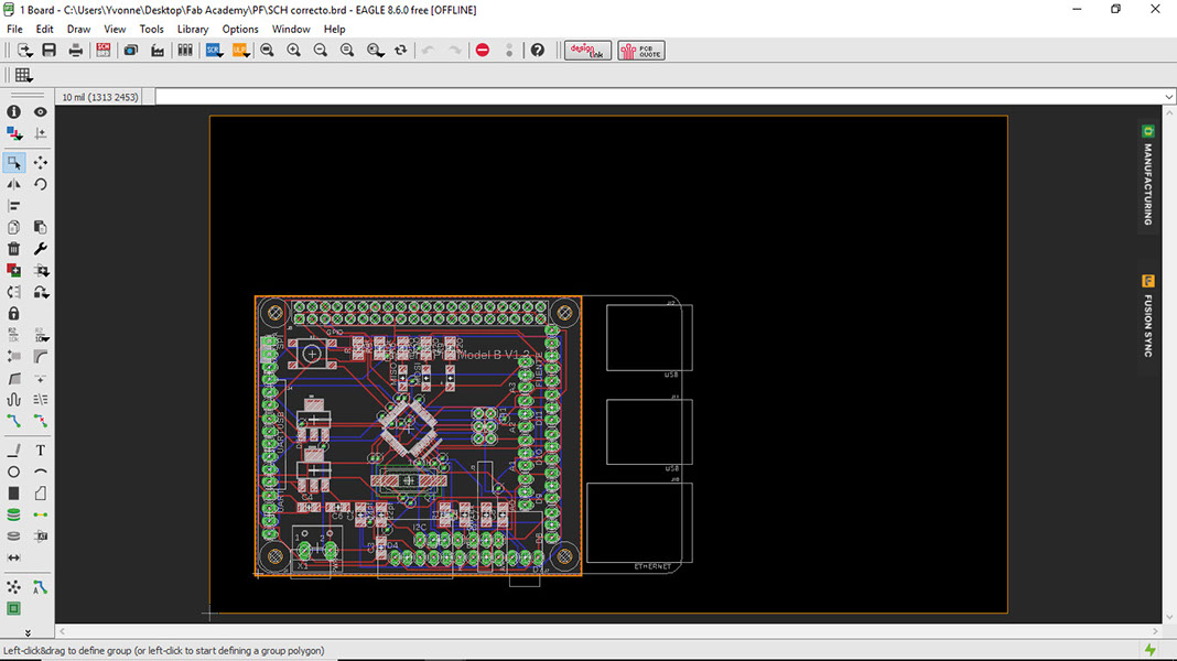
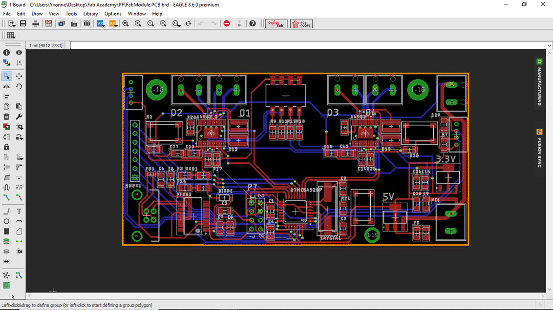
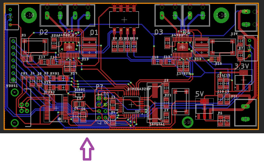
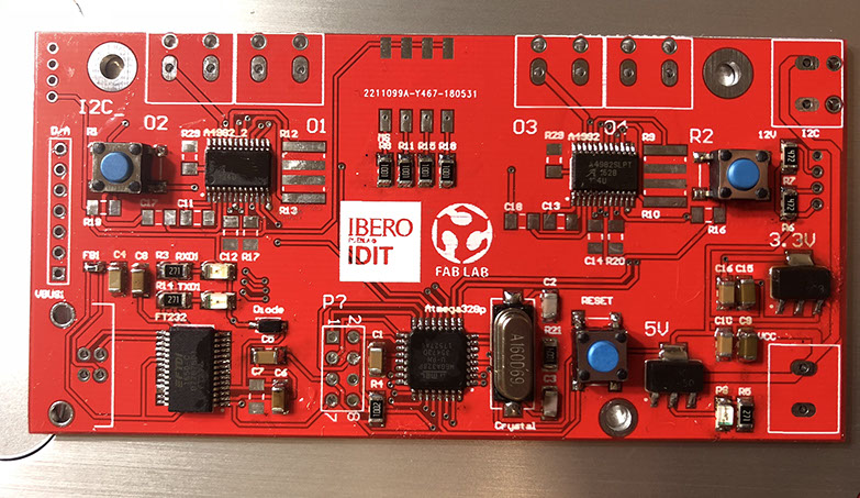
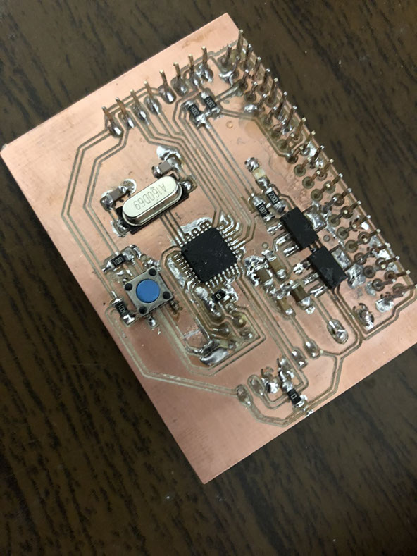
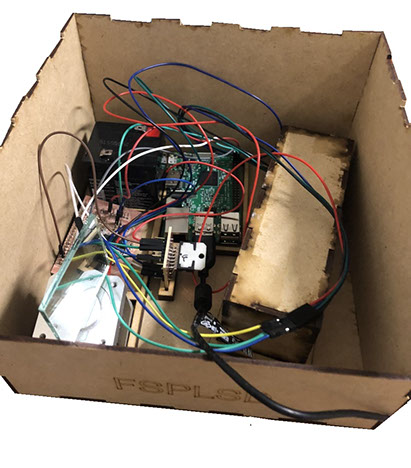
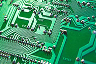
To communicate the Raspberry Pi with the camera I had to create a circuit. Below you can find the BRD and SCH files made for the circuit. The design is an original and I weld it, but I sent the design to a FabHouse to be made. By dimensions it is complicated to make the circuit in the model, it is complicated to do it in two faces especially the passage between the tracks. Therefore, it was ordered to manufacture a model with a Fabhouse carrying out the welding in FabPuebla. A plate with soldered like this is 20 times simpler than welding in copper since the solder is kept contained, the tracks are not stuck since it has finished Hasl that helps the welding. And Flux was also used for the soldier of the final plate which was not used in other tasks, that removes oxides and other impurities, so the tin flows better and is better welded. However, one was made in the model imitating the microcontroller and another one of the bridge H. Which were made in separate plates what was originally made in a plate by the complexities of the tracks. The send to manufacture helped a plane of the linked copper, which allows electronic stability which is not achieved so easily in the model.
It is important to note that the circuit is linked to a Raspberry. The components of the circuit are: Atmega328, three communication leds with their resistors, a button with its resistor, a 2x3 Pinhead, a crystal with two capacitors, a regulator of 3.3 Volts for the communication between i2 to c with raspberry, a regulator of 5 volts for the logic value of the Atmega (each with three capacitors), thirteen 1x3 Pinheads, two 1x4 pinhead (one for UART, the other for I2C), a 1x6 pinhead (for SPI), and a 1x5 pinhead for source.
Click hon the image to download file
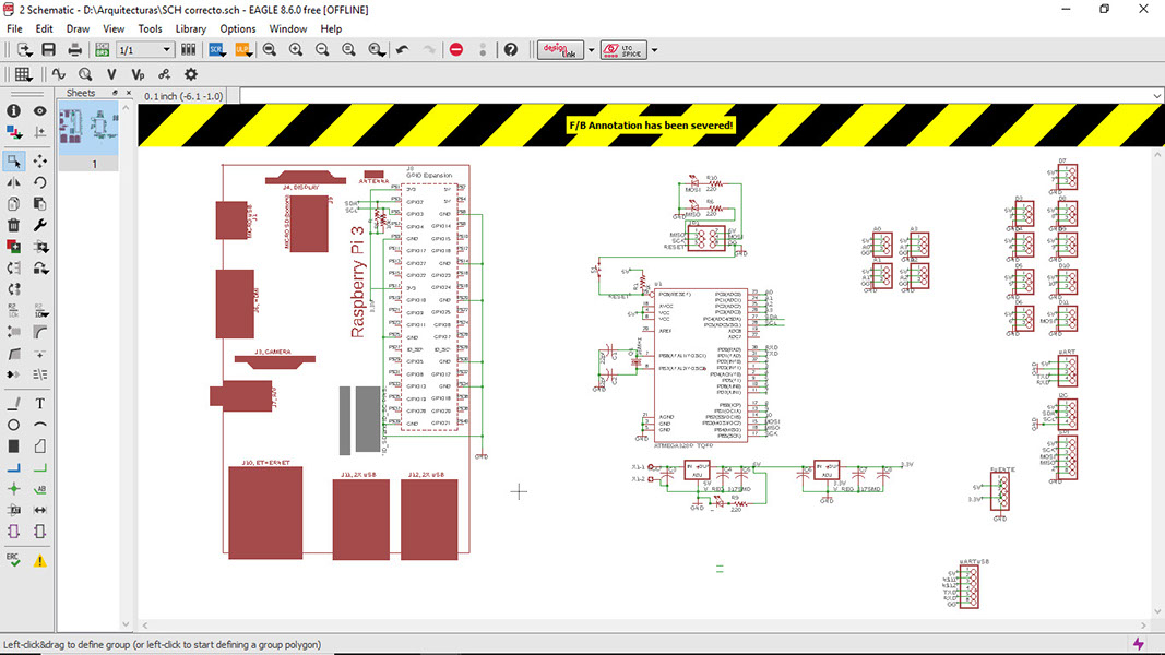
Click on the image to download file
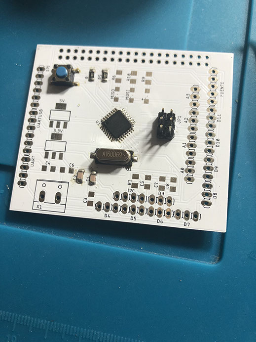
After I weld the components it looked like this (in the end I didn't use this circuit because I used the FabModul you will see next). I loved that this material makes it easier to solder, I I still burned a bit of the board you can see it in the yellow/ brown stains. I did need to ask for a bit of help with the Atmega.
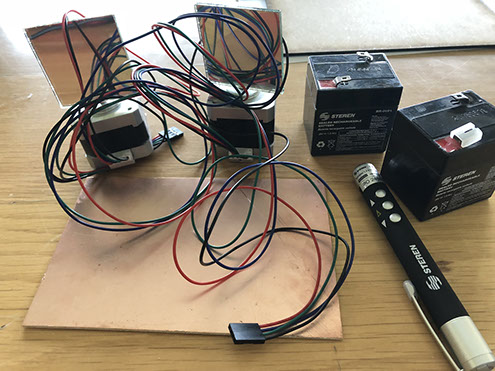
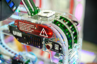
Then I had to program the motors, to do that I used a Fab module circuit .It is important to note that the motors work with batteries so the system is wireless. The components of the circuit can be seen in the image below:
I then decided to use a FabModul made for FabPuebla. With that module I don't need to use the other circuit, I just use the Module and the Raspberry PI.
Click on the image to download file
Click on the image to download file
Here is where the RF 433MHZ goes in case you want to use it..
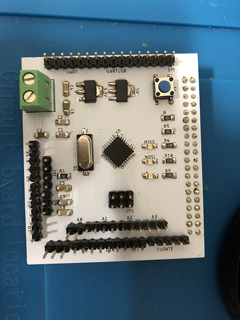
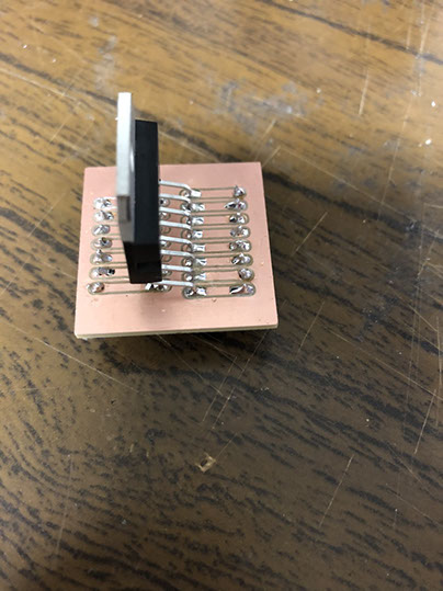
I designed the board but I sent it to be fabricated in a FabHouse. After I weld the components it looked like this.
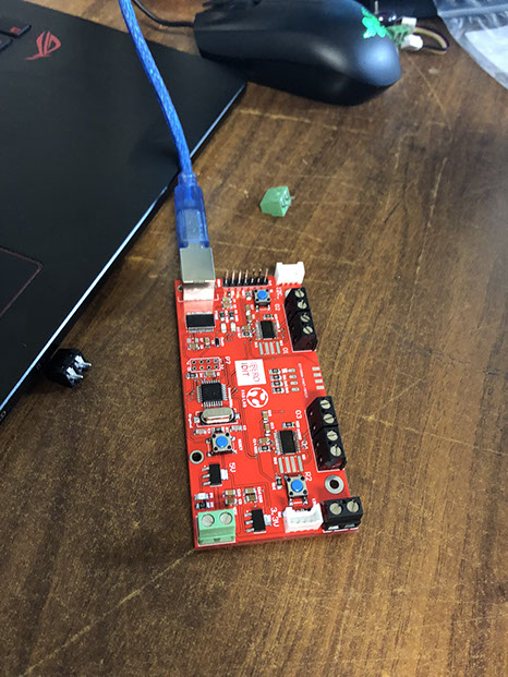
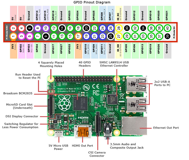
I used the Raspbery Pinout to connect it to the FabModul using GND, RX and Tx with I2C.
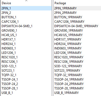
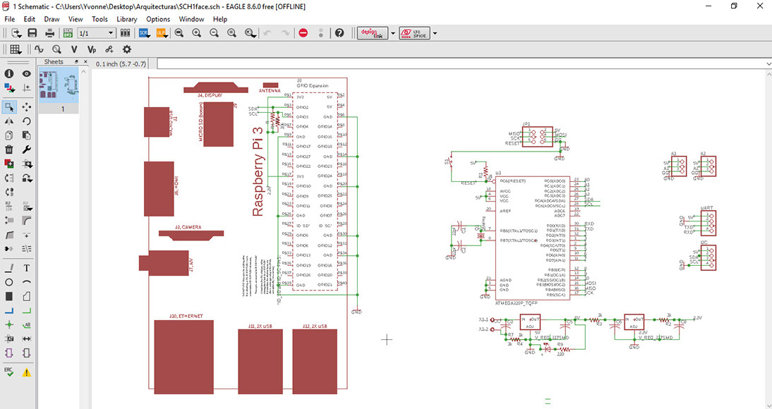
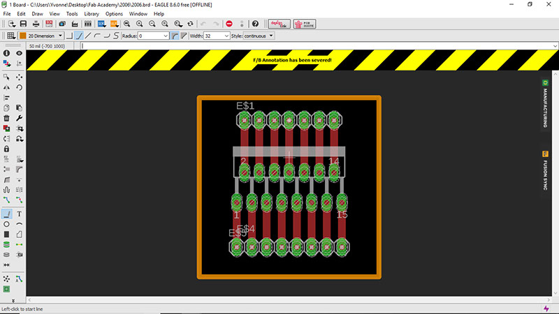
The next circuit can be manufactured in a FabLab (instead of the FabModul). The components can be seen in the second image. Its components are: pinheads, three 10 k resistors, three 1k resistor, two SML1206, two SOT223, con-wago-508, tact, Atmega 328, crystal, six capacitors C1206
Click on each image to download file

Click on each image to download file
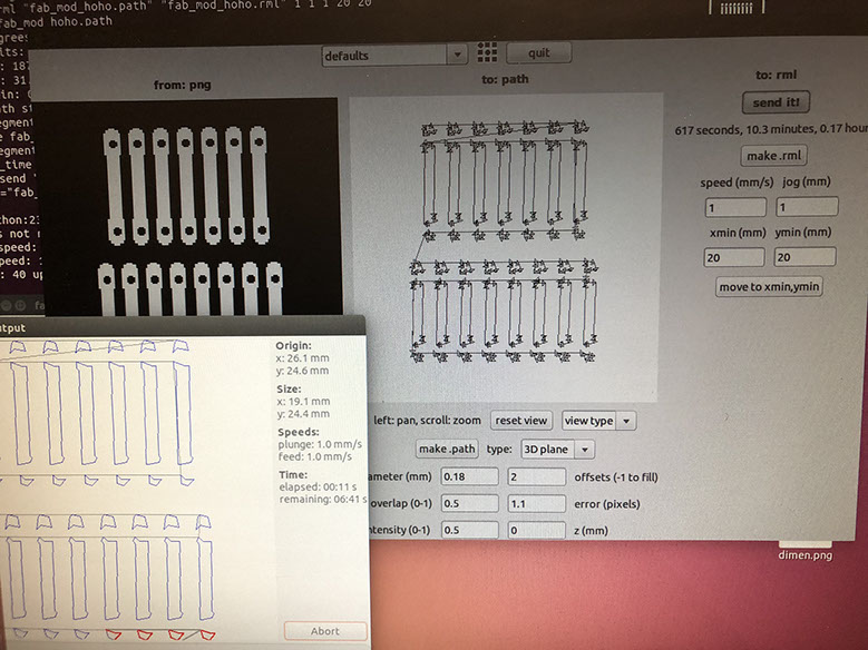
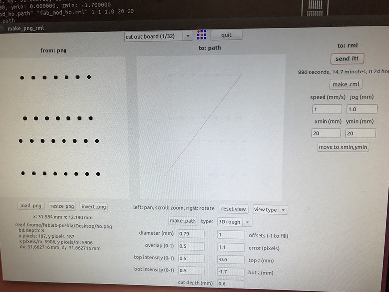
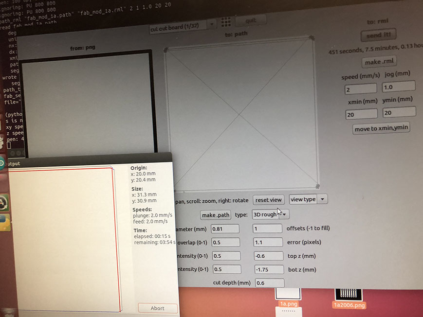
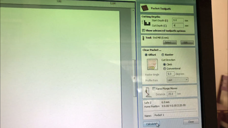
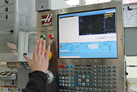
Below you can see the parameters used for the milling machine.
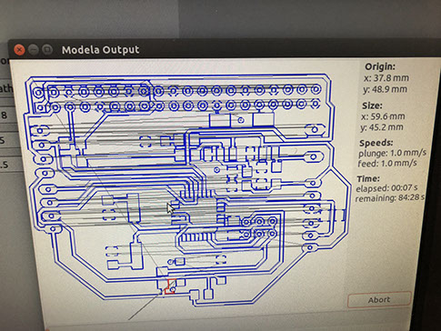
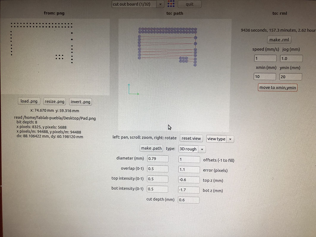
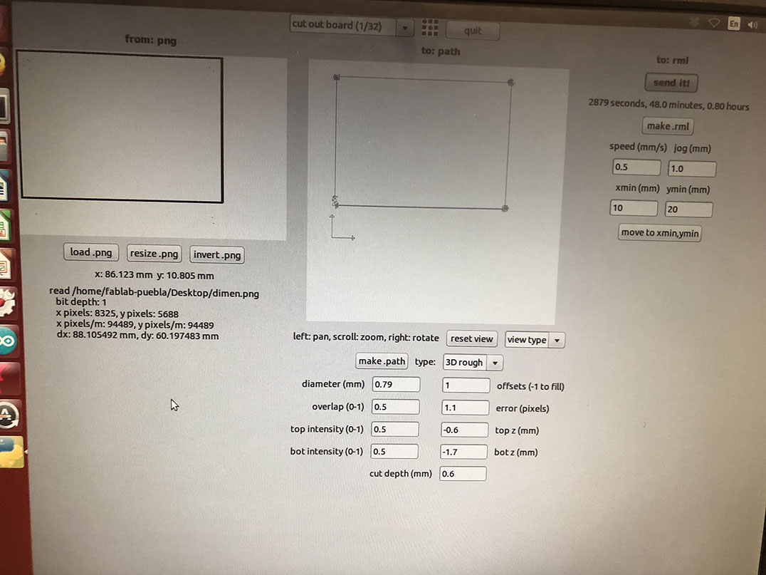
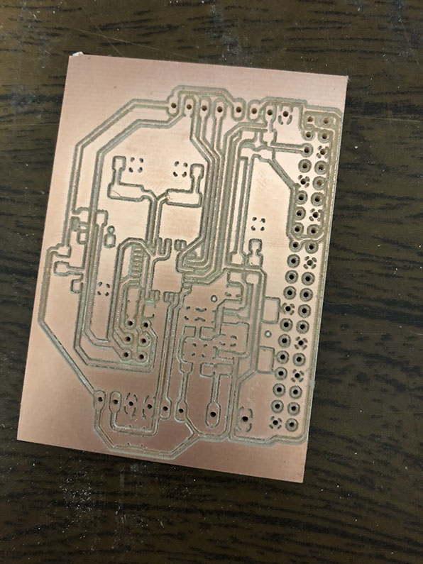
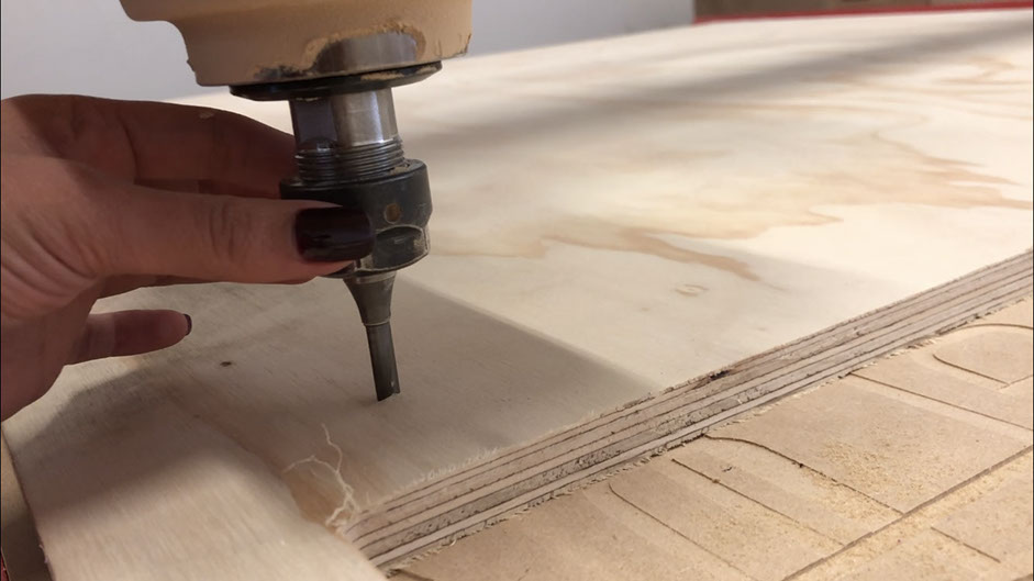
Here you can see the circuit being weld and finished, I loved it! It was cut very nicely :)
I also had to make a driver for the motor.
Click on each image to download file
Click on each image to download file


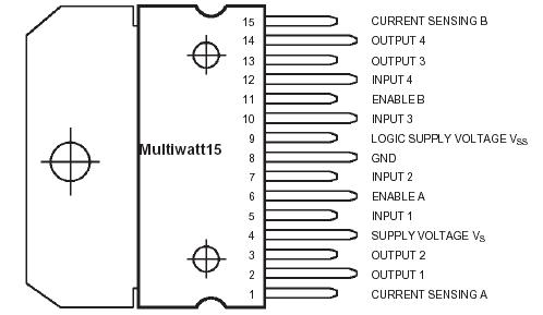
L298 pinout used to program the motor
Then I had to program the motors, to do that I used a Fab module circuit .It is important to note that the motors work with batteries so the system is wireless. The components of the circuit are: pins RaspberryPi (for connections), tact, resistors, crystal, Atmega328, SparkFun-IC-Power, Leds
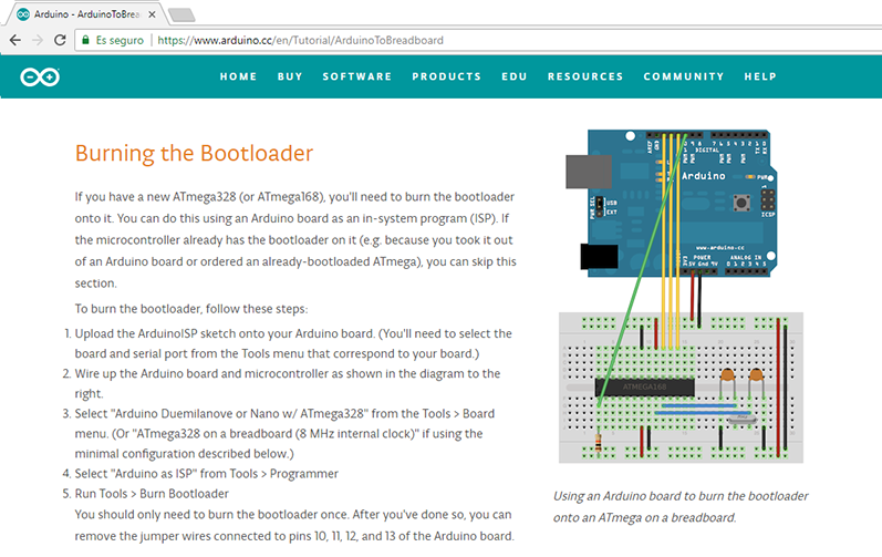
I used an Arduino tutorial to migrate from an Arduino board to a standalone microcontroller on a breadboard (The link can be found at the end of this page).
Because I have an ATmega328 I need to burn the bootloader onto it. I did it by using an Arduino board as an in-system program. The steps to burn the Bootloader are; first upload the ArduinoISP sketch onto the Arduino board. To do that it was necesary to select the board and serial port from the Tools menu that correspond to your board.) Then I had to wire up the Arduino board and microcontroller, and select "Arduino UNO" from the Tools > Board menu. Then I had to select "Arduino as ISP". It is important to only burn the bootloader once.
Once the ATmega328p had the Arduino bootloader on it, I was able to upload the program using the USB-to-serial convertor on an Arduino board. I had to remove the microcontroller from the Arduino board so the FTDI chip can communicate to the microcontroller on the breadboard. To program the microcontroller, I had to select "Arduino Duemilanove or Nano w/ ATmega328", then I was able upload.
I also had to test the car recognition program (which I found in a PDF written by, and the camera also has one program to recognize cars. I tried the first program with the Raspberry Pi, and then I realized I could do it without the Raspberry and just with the camera. I will also need to pin the camera to a self made board to give the signal that when the camera recognizes a car, it signals the motor to move so it can move the mirror and redirect the light so it reflects in the place where there is a free parking space.
Sadly I couldn't work with the Open MV M7 camera because I couldn't load the program so I decided to use a simple web cam and that made everything easier for me, but I encouraging to use the Open MV M7 camera if you have time because it is a very cool gadget. Also, using a simple web cam made my project way cheaper because the most expensive thing from my shopping list was the camera. I did use though a RF 433MHZ for the communication ( a transmitter and a receiver, in the end I didn't use it either)
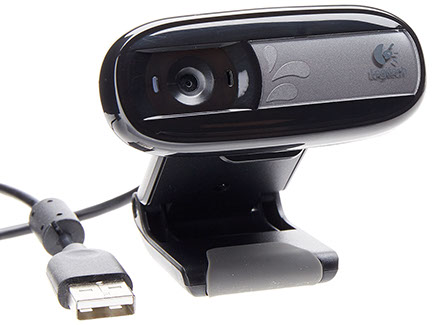
I ended using the CAMARA LOGITECC170 960-000880 that costs $18
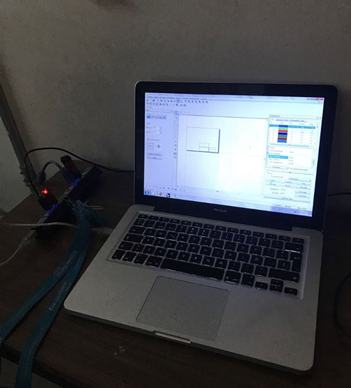
Below you can see pictures of the process made to program the project.
Then I had to program the circuit that can be made in a FabLab. The code for the Raspberry and the circuit can be found later on below.
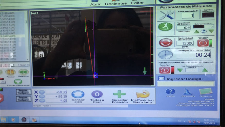
To program the controller I had to use an Arduino and program the Arduino with my code (it's important to make sure that you are in the correct Com. Then I had to set the Arduino so it would burn the Bootloader. Then I programmed the controller. Below you can find videos of me doing that.
To run the recognition program in the Raspberry you just have to open the file with the Raspberry and run it. To do that you'll need a monitor, a mouse and a keyboard. Below you can find the code).
Before using the program I made some manual test to get an idea of how I should calibrate the laser and the motors with the mirrors.
Later on, I had to correct the program to the version you will find below. Because the first program only worked with pictures, and I wanted it to work live with movement, and changing the position of the car. To show if there was a car in one or in the other parking space or if there was no car at all. This program is in Python and it works with a Raspberry Pi.
import cv2
import numpy as np
import smbus
bus=smbus.SMBus(1)
address = 0x08
def writeNumber(value):
bus.write_byte(address, value)
return -1
cap = cv2.VideoCapture(0)
car_cascade = cv2.CascadeClassifier('cars.xml')
width = cap.get(cv2.CAP_PROP_FRAME_WIDTH)
height = cap.get(cv2.CAP_PROP_FRAME_HEIGHT)
#print("Ancho: " + str(width))
#print("Alto: " + str(height))
area = (width * height) / 3
#print("Size: " + str(area))
while True:
ret, frame = cap.read()
gray = cv2.cvtColor(frame, cv2.COLOR_BGR2GRAY)
cars = car_cascade.detectMultiScale(gray, 1.1, 3)
for (x,y,w,h) in cars:
pos_x = max(x - 10, 0)
pos_y = max(y - 10, 0)
height2 = (y+h)-y
width2 = (x+w)-x
#print("Alto2: " + str(height2))
#print("Ancho2: " + str(width2))
area2 = height2 * width2
#print("Area2: " + str(area2))
porcentaje = (area2 * 100) / area
#print (porcentaje)
if(porcentaje > 10):
if(x < (width/3)):
if(cajon == 1):
cajon = 0
else:
cajon = 1
else:
if(cajon == 2):
cajon = 0
else:
cajon = 2
cv2.rectangle(frame,(x,y),(x+w,y+h),(0,255,0),2)
else:
cajon = 0
writeNumber(cajon)
print ("Carrito en cajon: " + str(cajon))
#cv2.imshow('video', frame)
if cv2.waitKey(25) & 0xFF == ord('q'):
break
cap.release()
cv2.destroyAllWindows()
Click on the image to download file
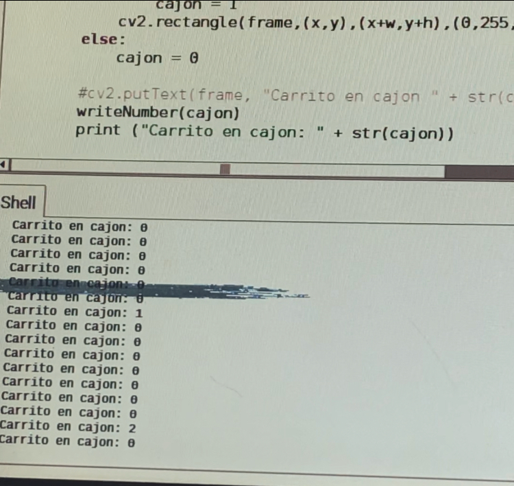
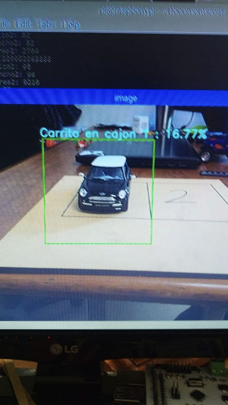
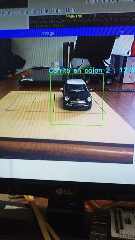
In the video above you can see how the program works. It sends a 1 when the camera detects a car parked in the first parking lot. It sends a 2 if the car is parked in the second parking space and a 0 if there is no car to detect. Depending if the camera detects a 1 or a 2, the motor with the mirror will move to redirect the light.
If there is a car parked in space 1, and space 2 is free then the mirror will reflect the light in the space 2 to show the user that there is a free space available.
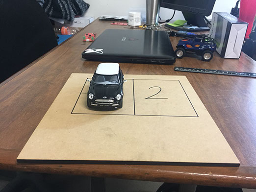
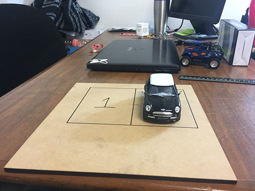
To show how the code works I took the next pictures with a miniature car, then I ran the program and as you can see it recognizes the car and its position. The link to the code is below.
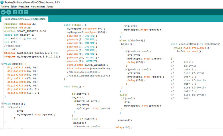
Here is the program created to control the motors.
#include <Stepper.h>
#include <Wire.h>
#define SLAVE_ADDRESS 0x08
const int pasos= 6;
int x=1;int y;int z;
int i=0;
//char buf;
int buf;
Stepper myStepper2(pasos,4,5,6,7);
Stepper myStepper(pasos,8,9,10,11);
void reposo(){
digitalWrite(4, 0);
digitalWrite(5, 0);
digitalWrite(6, 0);
digitalWrite(7, 0);
digitalWrite(8, 0);
digitalWrite(9, 0);
digitalWrite(10, 0);
digitalWrite(11, 0);
}
void bajar(){
if(z==1){
z=0;
myStepper2.step(-pasos);
}
}
void setup() {
myStepper.setSpeed(300);
myStepper2.setSpeed(300);
pinMode(4, OUTPUT);
pinMode(5, OUTPUT);
pinMode(6, OUTPUT);
pinMode(7, OUTPUT);
pinMode(8, OUTPUT);
pinMode(9, OUTPUT);
pinMode(10, OUTPUT);
pinMode(11, OUTPUT);
Wire.begin(SLAVE_ADDRESS);
Wire.onReceive(receiveData);
//Serial.begin(9600);
//Serial.println("Inicio");
}
void loop() {
if(buf==1){
bajar();
if(x==0 && z==0){
x=1;y=0;
myStepper.step(pasos);
}
}
else if(buf==2){
bajar();
if(y==0 && z==0){
y=1;x=0;
myStepper.step(-pasos);
}
}
else if(buf==3){
bajar();
{
if(x==0 && z==0){
x=1;y=0;
myStepper.step(pasos);
delay(250);
}
if(y==0 && z==0){
y=1;x=0;
myStepper.step(-pasos);
delay(250);
}
}
}
else{
if(z==0){
z=1;
myStepper2.step(pasos);
}
}
reposo();
delay(100);
}
void receiveData(int byteCount){
while(Wire.available())
buf=Wire.read();
}
// i=i+1;
// if(i==1)
// buf='1';
// else if(i==5)
// buf='2';
// else if(i==10)
// buf='0';
// else if(i==15)
// buf='3';
// else if(i==25)
// i=0;
This is the first version used to test how the motors move.
With this version you can change how many steps the motors do, in this case is 6 and I realized it didn't work out, because the laser light would reflect in the right reflector and it wouldn't reflect in the left one.
That was because 6 steps was too much, and when I tried with 5 it was too little and the light also wouldn't end in the right place. You can see what I mean in the video below.
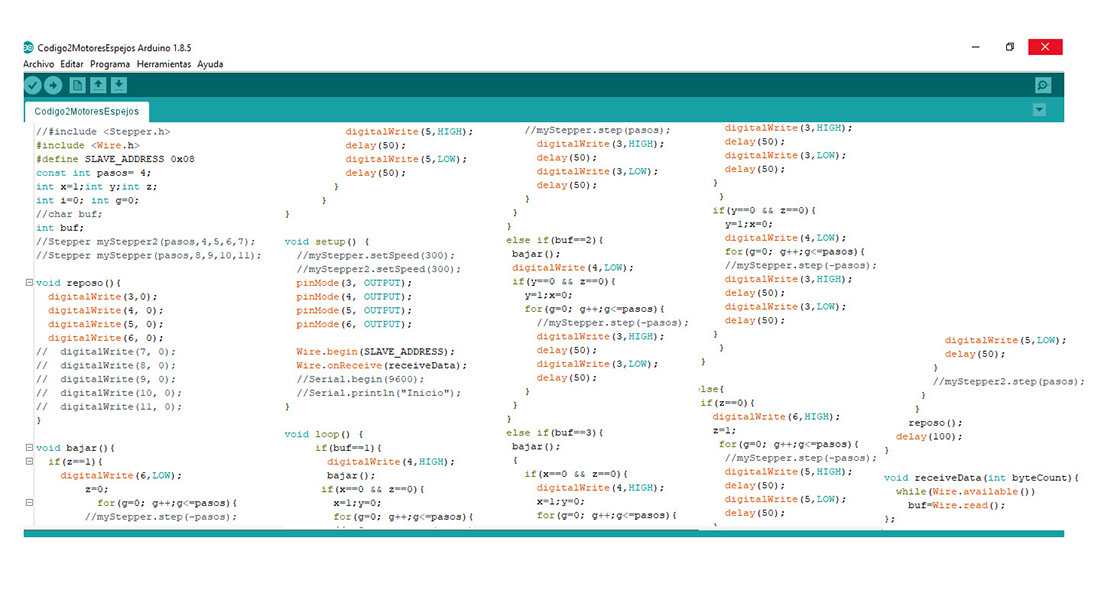
So I realized I needed to change the code to play with the steps until I finally lighted the reflector up (not perfectly). This has been a trial and error project.
Click on the image to download file
Here is the second program version created to control the motors :)
//#include <Stepper.h>
#include <Wire.h>
#define SLAVE_ADDRESS 0x08
const int pasos= 4;
int x=1;int y;int z;
int i=0; int g=0;
//char buf;
int buf;
//Stepper myStepper2(pasos,4,5,6,7);
//Stepper myStepper(pasos,8,9,10,11);
void reposo(){
digitalWrite(3,0); //motor 1
digitalWrite(4, 0); //sentido giro motor 1
digitalWrite(5, 0); //motor 2
digitalWrite(6, 0); //sentido giro motor 2
// digitalWrite(7, 0);
// digitalWrite(8, 0);
// digitalWrite(9, 0);
// digitalWrite(10, 0);
// digitalWrite(11, 0);
}
void bajar(){
if(z==1){
digitalWrite(6,LOW);
z=0;
for(g=0; g++;g<=pasos){
//myStepper.step(-pasos);
digitalWrite(5,HIGH);
delay(50);
digitalWrite(5,LOW);
delay(50);
}
}
}
void setup() {
//myStepper.setSpeed(300);
//myStepper2.setSpeed(300);
pinMode(3, OUTPUT);
pinMode(4, OUTPUT);
pinMode(5, OUTPUT);
pinMode(6, OUTPUT);
Wire.begin(SLAVE_ADDRESS);
Wire.onReceive(receiveData);
//Serial.begin(9600);
//Serial.println("Inicio");
}
void loop() {
if(buf==1){ //Empieza en el cajon 2
digitalWrite(4,HIGH);
bajar(); //Si está arriba, bajamos en y
if(x==0 && z==0){ //Verificar si el motor se encuentra en otro cajon
x=1;y=0;
for(g=0; g++;g<=pasos){
//myStepper.step(pasos);
digitalWrite(3,HIGH);
delay(50);
digitalWrite(3,LOW);
delay(50);
}
}
}
else if(buf==2){
bajar();
digitalWrite(4,LOW);
if(y==0 && z==0){ //Verifica si el motor se encuentra en otro cajon
y=1;x=0;
for(g=0; g++;g<=pasos){
//myStepper.step(-pasos);
digitalWrite(3,HIGH);
delay(50);
digitalWrite(3,LOW);
delay(50);
}
}
}
else if(buf==3){ //Alternar para ningun cajon
bajar();
{
if(x==0 && z==0){
digitalWrite(4,HIGH);
x=1;y=0;
for(g=0; g++;g<=pasos){
//myStepper.step(pasos);
digitalWrite(3,HIGH);
delay(50);
digitalWrite(3,LOW);
delay(50);
}
}
if(y==0 && z==0){
y=1;x=0;
digitalWrite(4,LOW);
for(g=0; g++;g<=pasos){
//myStepper.step(-pasos);
digitalWrite(3,HIGH);
delay(50);
digitalWrite(3,LOW);
delay(50);
}
}
}
}
else{ //Si ambos cajones estan ocupados, levanta en y
if(z==0){
digitalWrite(6,HIGH);
z=1;
for(g=0; g++;g<=pasos){
//myStepper.step(-pasos);
digitalWrite(5,HIGH);
delay(50);
digitalWrite(5,LOW);
delay(50);
}
//myStepper2.step(pasos);
}
}
reposo();
delay(100);
}
void receiveData(int byteCount){
while(Wire.available())
buf=Wire.read();
};
Click on the image to download file
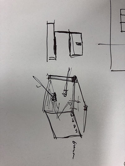
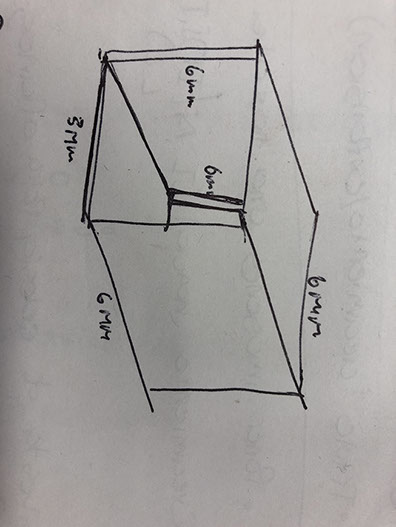
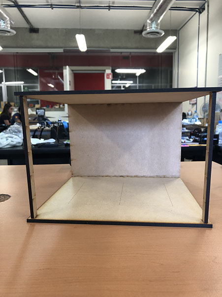
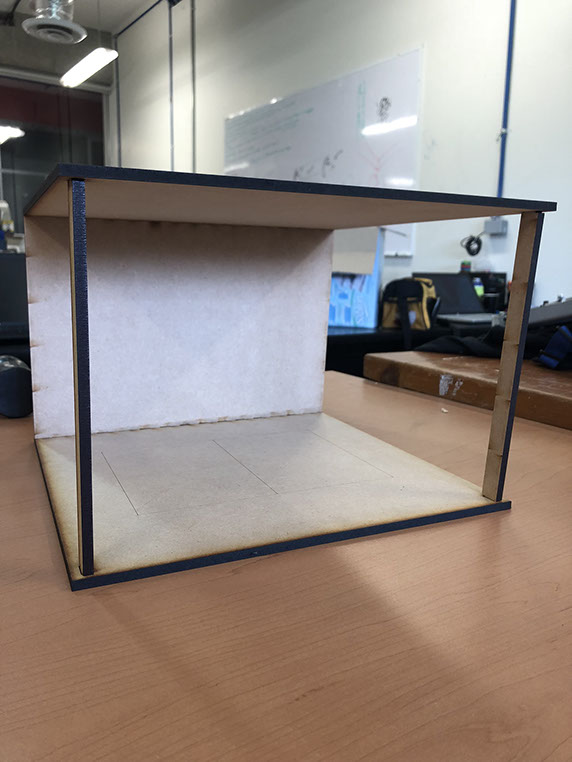
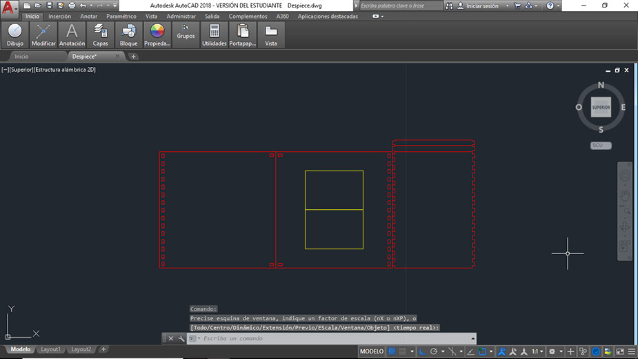
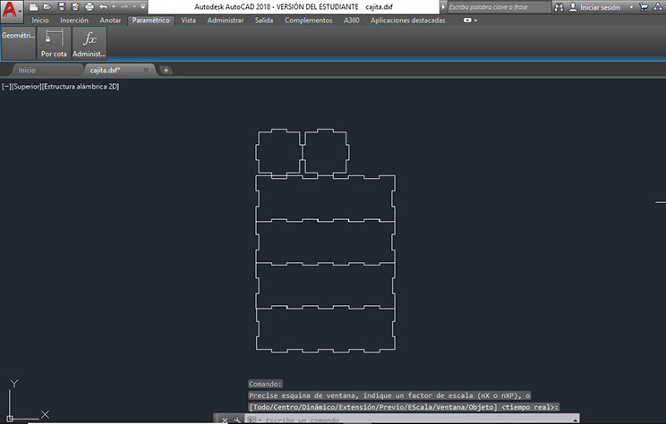
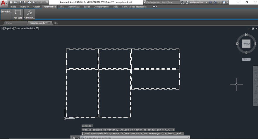
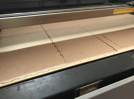
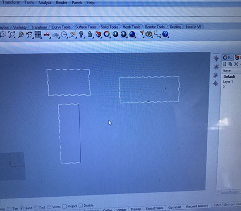
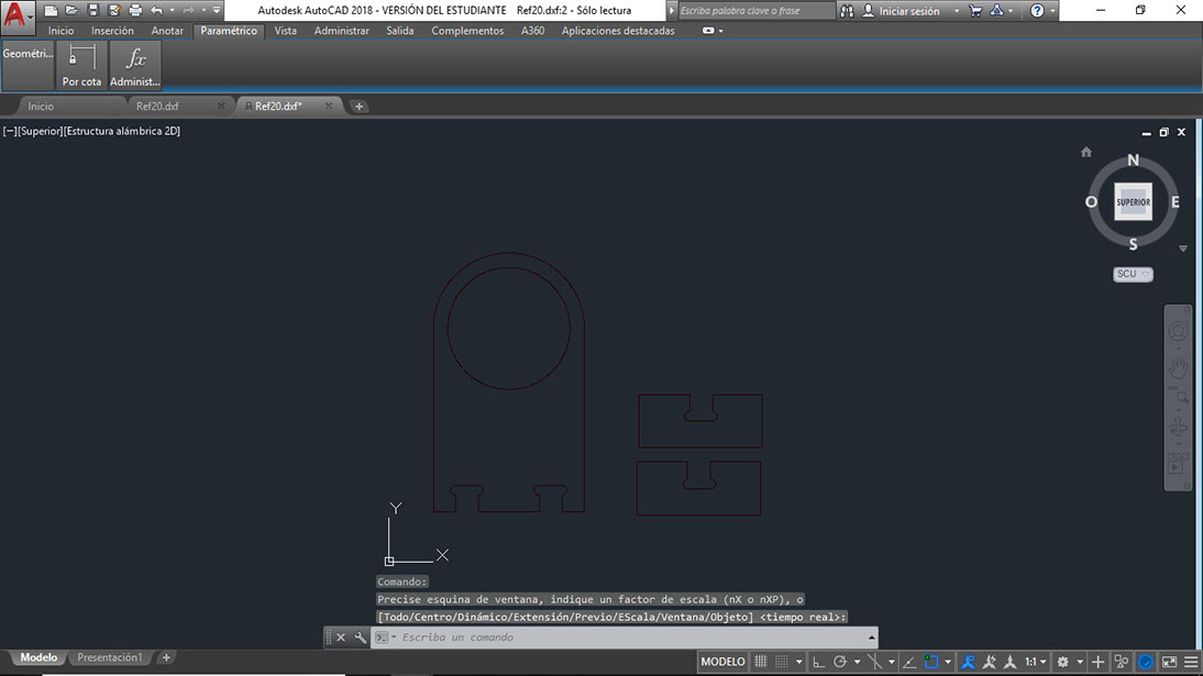
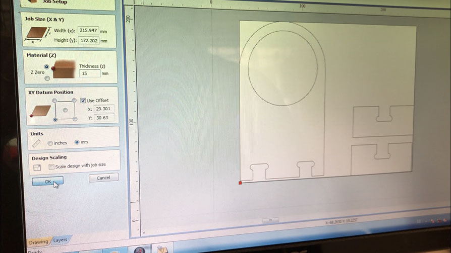
First I decided to show my project in a scale model, so I designed a simple parking lot for to parking spaces and I cut it in laser. Next you can see the sketch made for the model.
Click on the image
to download .dwg file
Right click and save as here for .dfx file
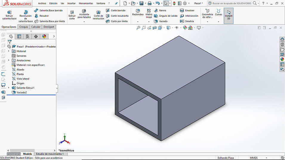
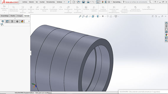
Click on the image
to download .SLDPRT file
Right click and save here to
to download .STL file
I also built small MDF box where the laser light could rest.|
Click on the image
to download .dwg file
Right click and save as here for .dfx file
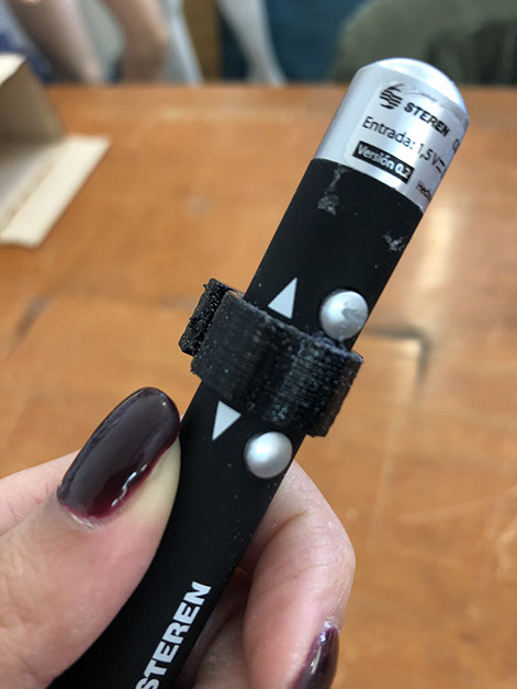
I used a bit of Velcro to make sure the laser wouldn't roll over, and to make it easy to change its position in case it was needed. Bad idea, that is not how digital fabrication is made... soo
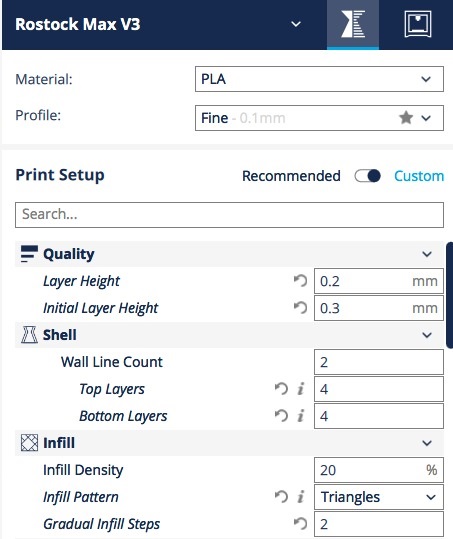
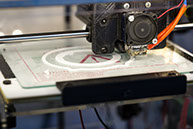
Then I decided it would be better to use 3D print so I created the next file to keep clicking the button of the laser beam without using the velcro.
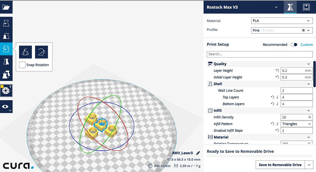
Right click and save as here for.stl file
Click on image f|or file
The parameters are in the next images
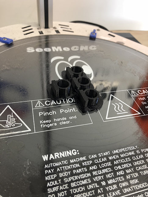
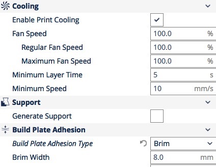
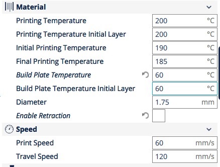
I printed four of this pieces in case I needed more. Below you can see how it works.
I also made a structure where the device could be stored. Its parameters are the same I used for the Computer controlled cutting assigment.
Here is the finished piece :D
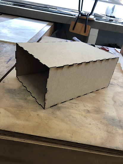
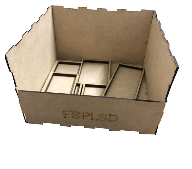
I realized the case was too small and simple so I made the next system integration. So it will be easy to move the device from one place to another (plus it is wireless because it orks with a battery). This way everything also stays in place inside the case.
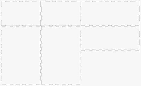
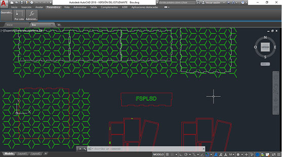
Click on image for .dwg file, Right click and save as here for .dxf file
Click on image for .dwg file, Right click and save as here for .dxf file
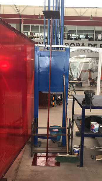
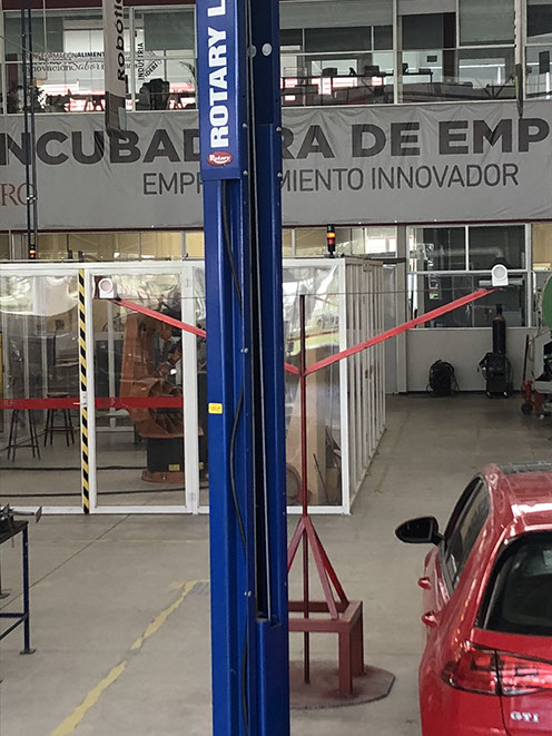
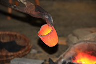
Then decided it would be better to test the device with real life cars. To test the device I needed two structures that were 2 meters and 10 centimeters tall, I decided to make them in steel so they would carry the weight and they wouldn't fall down (I couldn't take any chances with the cars, I didn't want the structure to fall over a car).
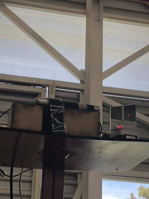
The first structure is very simple it has a base a support and at the top a plaque t place the camera and the circuits as well as the laser. This structure goes in front of the cars about 3 meters away from them and right at the middle.
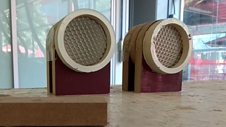
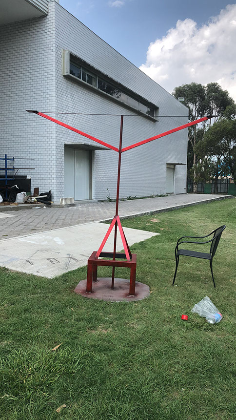
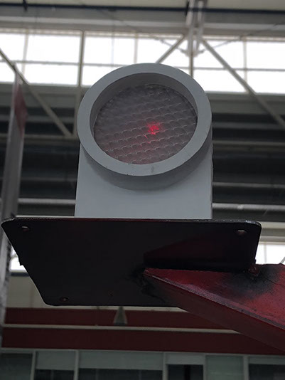
The second structure is very similar to the first one it is has the same height, but it looks like a T, so its top plaque can carry two reflector that are at the top of the cars. These reflectors are the ones that indicate the user if the parking space is free or occupied.
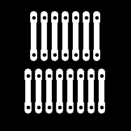
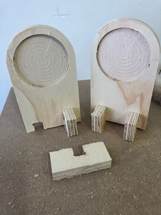
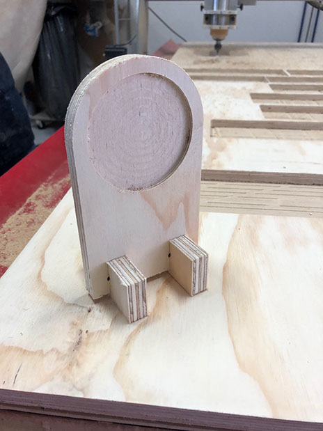
Below you can see the reflectors and a video of them. The reflectors where cut with the router and inside of each one is a mirror covered with plastic so the light looks broader.
Right click and save as here for file
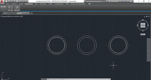
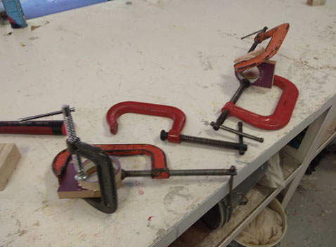
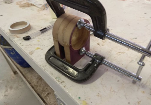
Here is a set of reflectors that are pressfit.
Right click on the image for .dwg file or right lick and save as here for .dxf file
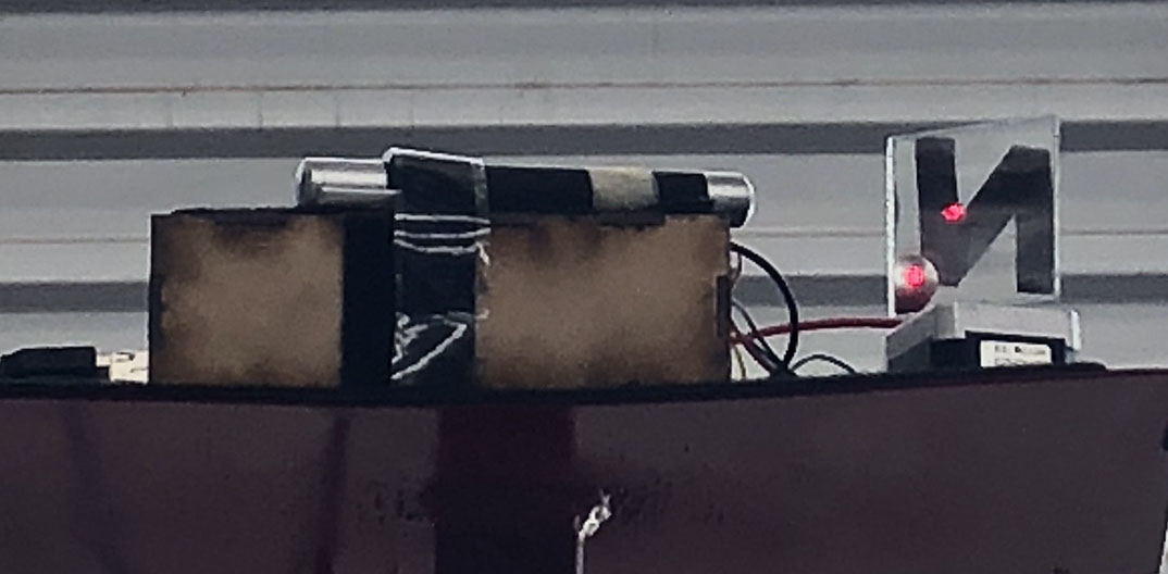
Below you can see the final structure made in steel, and a video of the functioning device.
The image to the left has the structure that will hold the reflectors, one in each extreme. The picture to the right is the structure that ill hold the laser and the motors with their mirrors, as well as the circuits and the batteries.
Summary:
This device is a machine that lets you know ere there is a free parking space. All you have to do is enter a parking lot and look for the light. There will be a shining light above all the free spaces. The light shines above a free space because it is linked to a system with a camera that recognizes cars, if there is a car parked in a space then the camera recognizes that the space has a car and it sends a signal so there won't be a shining light above it. The light shines above the free space because it is redirected with a mirror. The mirror moves because it is attached to a motor, and the motor has a program that is linked to the car recognition program.
In some parking lots there is a red or green light system, which allows the driver to identify where there are free spaces to park his car. Those works with sensors and wiring in the parking lot, and it implies high maintenance costs and infrastructure.
I designed the circuit for both the motors as well as the camera. I also designed the parking lot model, the box for the laser, the 3D piece and the reflectors.
The materials used are:
OfficeMax: CAMARA LOGITECC170 960-000880 that costs $18
Mauser: Raspberry Pi 3 Model B+ ($40)
Japo Electrónica: two phenolic plaques, receptor and transmissior Modul RF 433 MHZ ($30)
Steren: two Motor Stepper NEMA 17, L928 Modul Driver, wo rechargeable lead acid 6 batteries, a lase light pointer ($65)
Fab Lab Puebla: ins, button, two 10k resistors, three 220 resistors, 3 Leds, one VREG 5V, one VREG 3.3V, Atmega328, 16MHz, six capacitors, two 22pf, jumpers, MDF.ax.
A set of circuits were manufactured in a Fabhouse. The last circuite was designed miled and weld in the FabLab Puebla by me. he model, the laser box, the reflectors and the structure were fabricated in FabPuebla also by me. The laser box and the small parkinglot model were designed in Autocad and cut with the laser cutter. The reflectors were cut in the CNC router and the programs for the circuits were built in Arduino program.
I answered the question of how I would communicate the motors movement with the car recognition by using a rapsberry and two circuits (each for one different operation either moving the motors or recognizing the cars).
I evaluated the function ability of the system by testing the circuits, first I "played" with the car recognition. I realized that I needed to be able to "see" the car from a top front view for the program to work properly. Then I had to test the angle of the web cam to be able to see the program recognizing the car in either parking space 1 or parking space 2. I also thought I needed two mirrors to reflect the light, by trying and trying I realized that it was enough with just one mirror and a static laser beam. Once I had the car recognition program working, I tried to calibrate the laser light with the mirror to be able to reflect the light right in the middle of the reflectors. It was to hard, and I was only able to reflect it in the reflector either on the side or a bit below the reflecting space. Being able to reflect it right in the middle was too hard, probably because my motor wasn't that precise.
I designed the small parking lot model in 2D as well as the laser box and the reflectors. I designed the parking lot model in 3D, it was quite a simple model, but it help me get an idea of what I wanted to do. In the end I decided I wouldn't use the small parking model and I made it real size. I made the reflectors with the CNC Router. A circuits I designed them and I weld them but they were fabricate din a FabHouse, the other circuit was designed, milled and welled by me in FabPuebla. I also programmed the programs for both circuits (one to move the motor the other to recognize if a car is parked in parking space 1 or 2).
The project can be bettered by using a more powerful laser beam, also by calibrating better the mirror by using a more precise motor, to center the laser light in the reflector.
The project can also be bettered by using more parking spaces, probably then it would be needed to use more than one mirror with one motor.
It can also be greater if programmed to work in a whole parking lot ail, probably that would need more mirrors and a more powerful motor.
Click here for all the files you need to replicate the project
Sources and inspiration used:
htCamera code: tp://acodigo.blogspot.mx/2015/12/entrenar-opencv-en-deteccion-de-objetos.html
Arduino: https://www.arduino.cc/en/Tutorial/ArduinoToBreadboard
ASSIGMENTS


1
2
3
Principles and practices, great projects, introductions, final presentations
Project management
Computer-aided design


4
5
6
Computer-controlled cutting
Electronics production
3D scanning and printing

7
8
9
Electronics design
Computer-controlled machining
Embedded programming


10
11
12
Molding and casting
Input devices
Output devices


13
14
15
Interface and application programming
Networking and communications
Mechanical design


16
17
18
Machine design
Wildcard
Applications and implications

19
Team Work
Final Project
Invention, intellectual property, and income
Mechanical and Machine Design
20
Parking space detection
Click here for Final Project Development
ABOUT ME

YVONNE
I like to learn new things and I really love a good challenge. I see a world where there are diverse ways of doing things, where it is important to have a different mind-set on how to solve problems. I have a Master’s Degree in “Logistics Engineering and Supply Chain Management”, and a Bachelor’s Degree in “Business Engineering. I believe that being part of Fab Academy is an amazing opportunity to learn skills regarding digital manufacturing. To me, it is a place where people make, create and share, always collaborating with each other.
CONTACT
ylmont.47@gmail.com
+52 222 349 8422