14

Networking and communications
What I learned: How to design and build a wired network connecting at least three processors.
Sources and inspiration used:
Examples Arduino:
Master: Nicholas Zambetti
Slave: BroHogan
What I did:
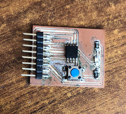
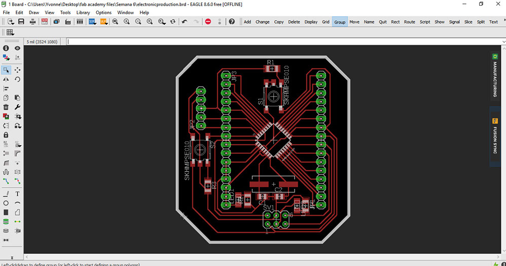
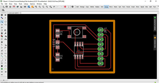
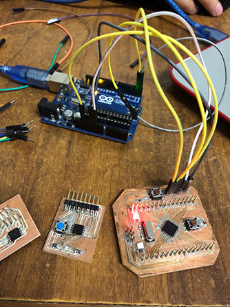
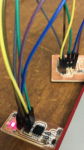
I decided to communicate three cards,they all have Leds so the message that is sent between theme is seen as received once the Led is turned on. The first card I used is one I previously made for another assignment. The second one is similar to the first one because it also uses an Itiny45.
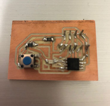
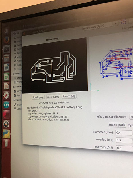
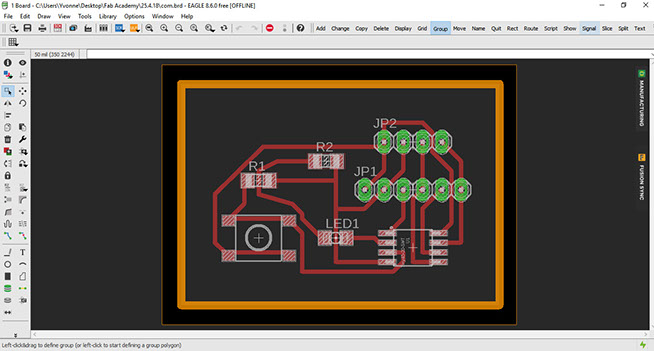
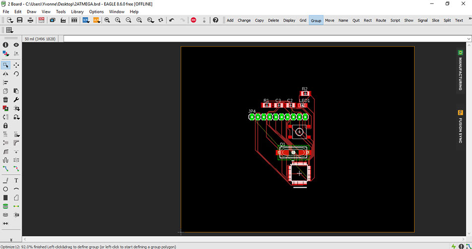
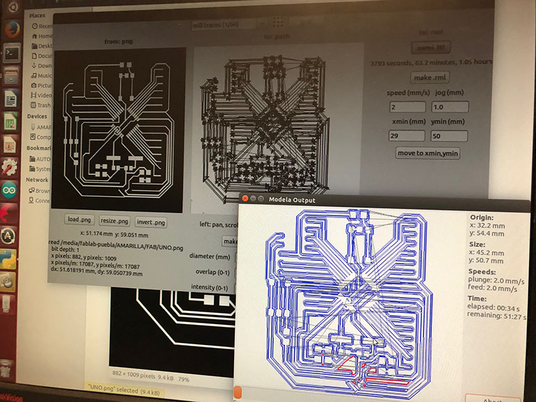
The third one however uses an Atmega82 below you can see the pictures of the process, but somehow I couldn't manage to make the route.
The communication works using three wires so Tx, Rx and Ground are communicated. To connect the ports it is necessary to use wire between the pins from one device to another. Below you can see the codes used to configure. It is important to configure all the devices with the same baud rate.
I managed to communicate the buttons of two boards so when one receives an Input it's send to the other (using Atiny and Atmega).
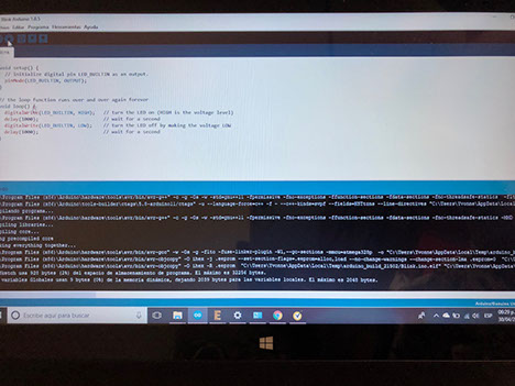
I first had to make the code for each ATiny, they represent the slaves. After that I made the master code for the Atmega. I programmed the first two codes with CDM in my computer writing cd desktop" to access the files in your desktop, then write "avrdude -c usbtiny -p t45 -U flash:w:(name of your file).hex
To program the ATmega I had to use an Arduino UNO, it was a lot of fun and it helped me learn and practice what I have learned while wiring from one card to another. I wanted to be able to comunicate between three devices but I only managed to to it with two, that's because my third card had a short circuit. And therefore the communication couldn't go through.
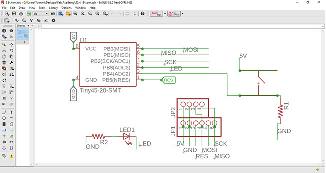
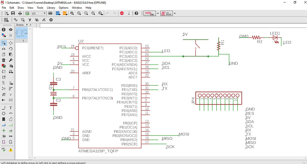
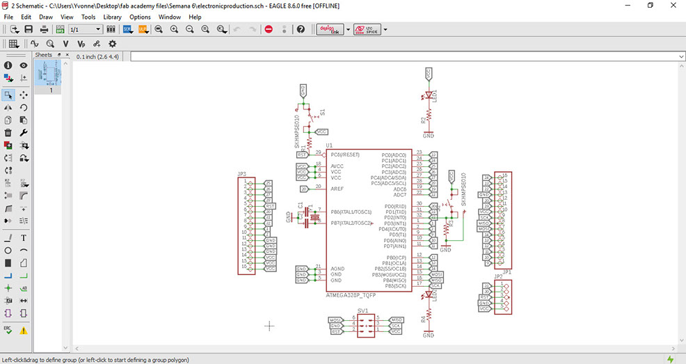
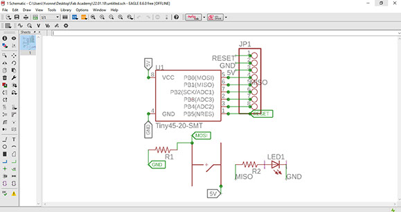
Below in the SCH images, you can see all the components needed for the three devices.
As a group assignment we tried to communicated our devices with each other.
Click on the image
to download file
Click on the image
to download failed try with Atmega file
Click on the image
to download file
Click on the image
to download file

Click on the image
to download file
Click on the image
to download file
Click on the image
to download file
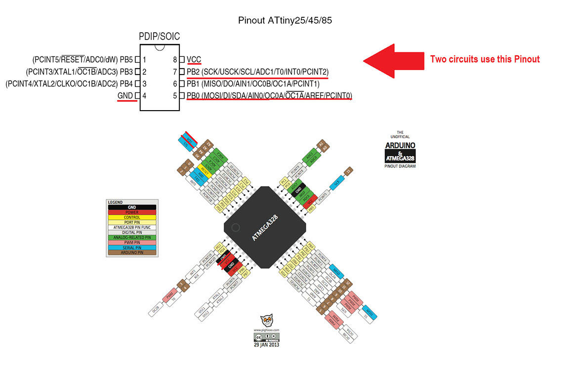
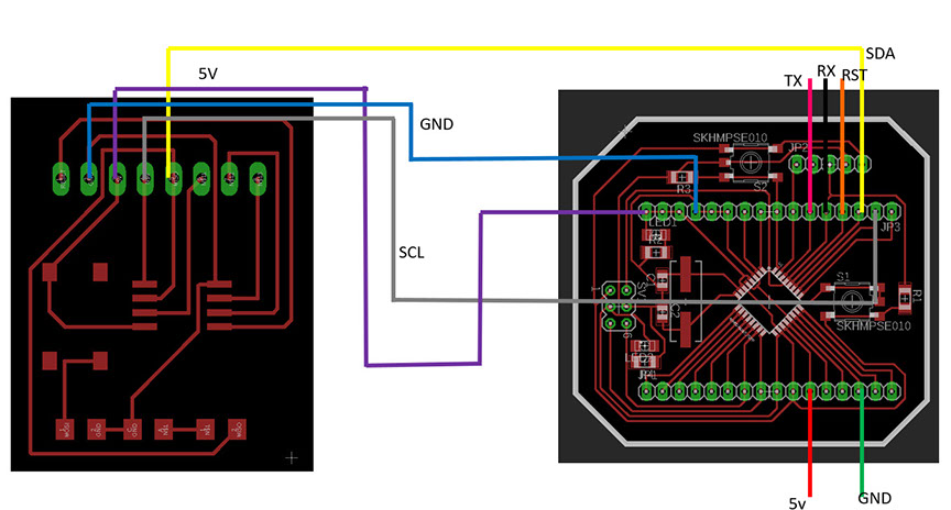
I used four Atmega 328 pins: 5V, GND, SCL and SDA.
Then I connected those pins to the first Atiny, connecting 5V to 5v, GND to GND, SCL to SCK and SDA to MOSI.
Finally I connected those pins to the last Atiny, conecting 5V to 5V, GND to GND, SCK to SCK and MOSI to MOSI.
In the end I only communicated two circuits (the ones you can see in the video below), that is because my third circuit didn't work out.
To see what the communication is, you have to take a very close look to the circuit in the right (it was a blue led, and it turns on and off, but the light is a bit low, so you have to look carefully)
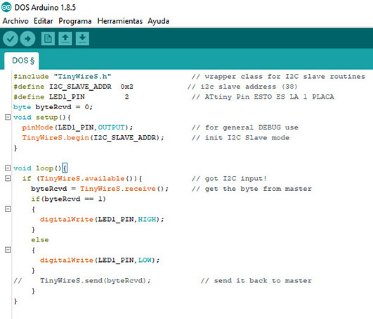
The first program is a slave (so it depends of the master), first I had to define the pins to work with. In this case was the LED. Then I had to tell the program to initialize, after that I told it to do a loop, so it would repeat the same process over again. The process consists that if the I2C input was available or it equaled 1, then the LED should be turned on (that's why it is linked to HIGH). In case it didn't equal 1, then the LED should be turned off (therefore it is LOW).
The second program is also a slave, and it is actually the same program as the one stated above, the only difference is the LED pin, that in the first program was 3 and in this case it's 2, but that is because of the design of the circuit. Everything else works just the same.
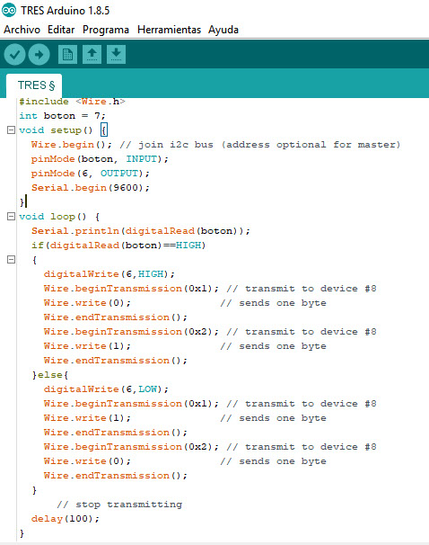
Finally the third program is the master and this one is programmed in the Atmega. First I had to let the program now where the button is, in this case it is linked to the pin number 7. Then I tell the program to begin, and tell it that the pinMode is related to both the button and the input, as well as the output and pin number 6. In this case the loop is in relation to if the button has be pressed (that's why it's stated as HIGH). That all so the transmission between the circuits can begn. I have two sets of Wire.begingTransmission because I have two circuits with the slave program. If any of those slave circuits is in HIGH then it should turn on the LED else it shouldn't.
It should have a delay of 100. All the programs can be found in the example library in Arduino.
Below is a layout for the connections.
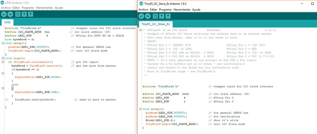
In the image to the left you can see my code and in the image to the right you can see the arduino example I used. This code is for the slave circuit. I had to define the salve and its address. I also had to tell the program which was the pin of the Led.
Then I had to tell it that it would receive the information from the master, and that the Led would be on or off by writing HIGH or LOW. Before all that I had to make sure the program was working with the correct ATiny (that is in this case ATiny 45).
I made tha same code for the other circuit, which was also a slave.. but it didn't work put that's why I didn't post the picture (to not confuse you), the only difference is the pin.
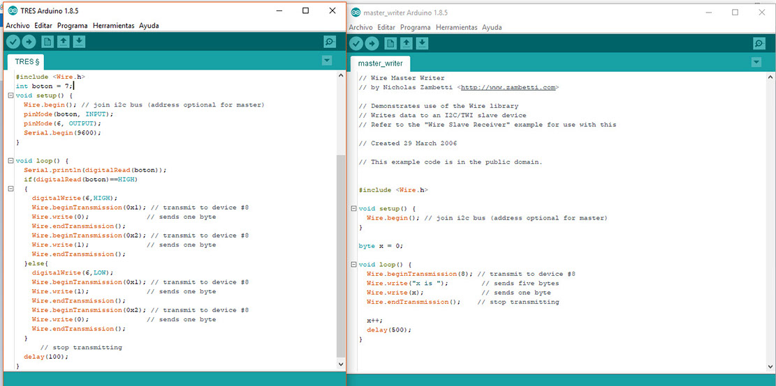
The pictures above are of the master program. The one to the left is my code and the one in the rite is the Arduino example.
I had to first state where is the button in my circuit, in this case is pin 7. Then I had to adress the input and output with the usual Serial.Begin at 9600.
Then it came the loop, to let the master now that when the button is pressed (as in HIGH), it should write HIGH and begin the transmission to the slave, if it is on it should send a 1 and if it is LOW or off it musts end a 0. At the end I stated that it should have a delay of 100.
Click here to download BroHogan file
Click here to download Nicholas Zambetti file
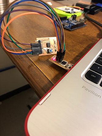
In the picture below, you can see an Arduino 1 connected to the Atmega circuit, I used the Arduino as a UART converter (A UART is a universal asynchronous receiver-transmitter is a computer hardware device for asynchronous serial communication in which the data format and transmission speeds are configurable).
I didn't use the Arduino, I used the converter chip from a USB serial. In the board I took out the microelectronic to communicate to the computer to the bard with the serial converter. Because the FabISP couldn't convert serial.