12

Output devices
What I learned: How to add an output device to a microcontroller board, one that I have designed, and also program it to do something (in this case to turn on and off two light bulbs).
Sources and inspiration used:
Outputs Carlos Perez http://archive.fabacademy.org/archives/2017/fablabpuebla/students/244/week-10.html
Arduino: Examples button
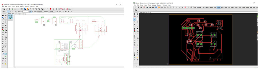
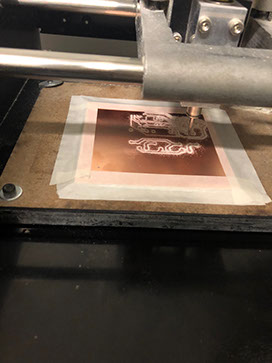
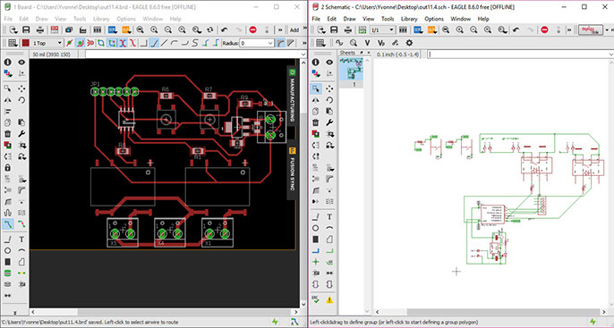
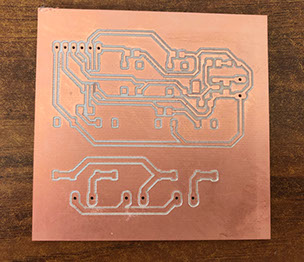
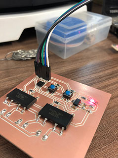
What I did: For this assigment, I decided to elaborate an output consisting of two bulbs which can be turned on by means of the program programmed in the circuit. The first step was to design the circuit, which is similar to the previous class, however, it uses a Tiny 45. Once the SCH program was ready I traced the tracks in BRD. I found very useful the assignment made by Carlos Perez,the link can be found at the bottom of this page. After the design was finished, I cut it in the milling machine, later on I welded its components, programed the card and attached the bulbs as you can see in the images below. I took my time to weld each component because it's a delicate and difficult task for me. Afterwards I programmed the code for the card, I used a Button example found in Arduino and I changed its values. Later one I used cable to attach the bulbs to the card as well as to the electric current. As a group we measured the power consumption of an output device. It is important that while working with high voltage, it is important to use an antistatic wristband to avoid burning the components when soldering them. In the same way it is import that the cables that can not be touched and that at the same time generates a short circuit and an explosion (a you can see my mistake in the video below).
The code is below:
// constants won't change. They're used here to set pin numbers:
const int b1 = 0; // the number of the pushbutton pin
const int f1 = 3 ; // the number of the LED pin
const int b2 = 1; // the number of the pushbutton pin
const int f2 = 4 ; // the number of the LED pin
// variables will change // variable for reading the pushbutton status
void setup() {
// initialize the LED pin as an output:
pinMode(f1, OUTPUT);
// initialize the pushbutton pin as an input:
pinMode(b1, INPUT);
// initialize the LED pin as an output:
pinMode(f2, OUTPUT);
// initialize the pushbutton pin as an input:
pinMode(b2, INPUT);
}
void loop() {
// read the state of the pushbutton value:
// check if the pushbutton is pressed. If it is, the buttonState is HIGH:
if (digitalRead(b1) == HIGH) {
// turn LED on:
digitalWrite(f1, HIGH);
} else {
// turn LED off:
digitalWrite(f1, LOW);
}
if (digitalRead(b2) == HIGH) {
// turn LED on:
digitalWrite(f2, HIGH);
} else {
// turn LED off:
digitalWrite(f2, LOW);
}
}
Click on the image
to download file
Click on the image
to download file

Click on the image
to download file
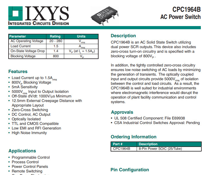
Output CPC1964C, Switch in solid state that internally has a led like an optotriac where it has two h diodes.
One side allows ac and the other side the Led. This is only for high charges, because if I try to pass a dc for the way it's made it won't let it through, because it will be waiting for a change. AC works back and forth and DC is a flow direct to the light bulb.
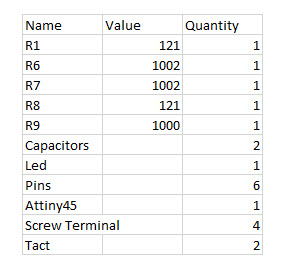
Using the electronic plaque design I searched for the same formula, the value of the resistance is at least 100, working with maximum capacity. That's why I used a smaller resistance (half the value).
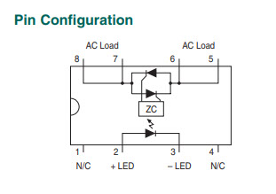
Above you can see the pinout of the ATtiny and the CPC1964B with that you can now how to connect the jumpers to which pin.
Click on the images
to download .png files
This is the ATtiny 45 features
This is the CPC1964B Datasheet
This is the CPC1964Bpin configuration
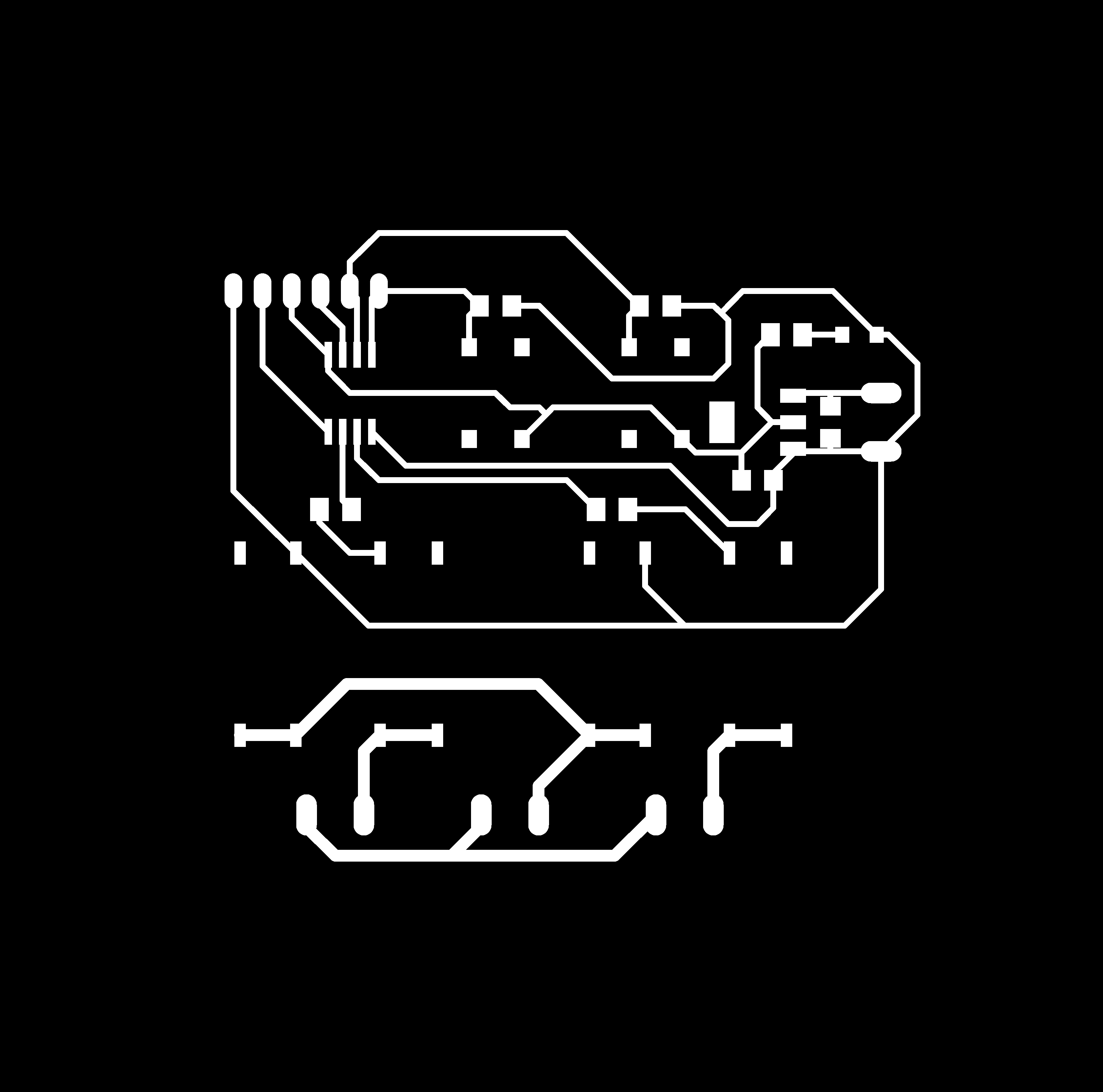
This is my circuit
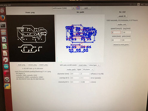
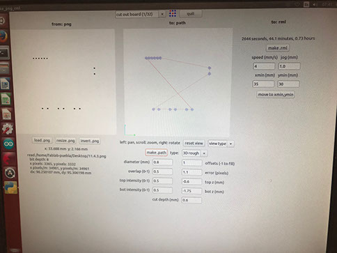
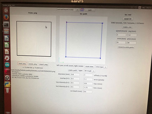
This is the modela window to cut the perimeter of the circuit
This is the modela window to cut the circuit
Left is the modela window to cut the holes in the circuit
This is the circuit cut
Below are the images needed to cut the whole circuit
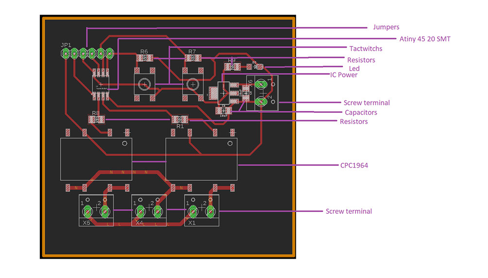
This is an explained circuit layout
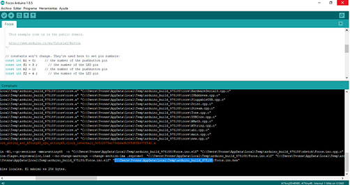
Example of the program being programmed and where to find it
Video of short circuit
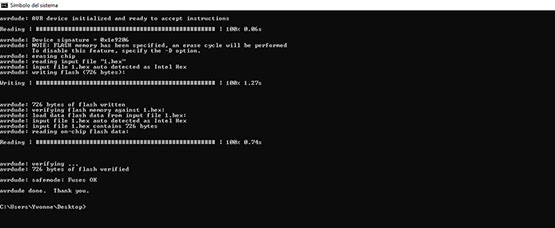
The circuit being programmed
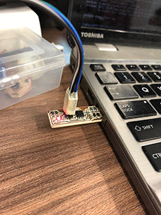
Uploading the program to the circuit
Video of working circuit
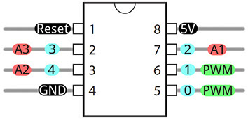
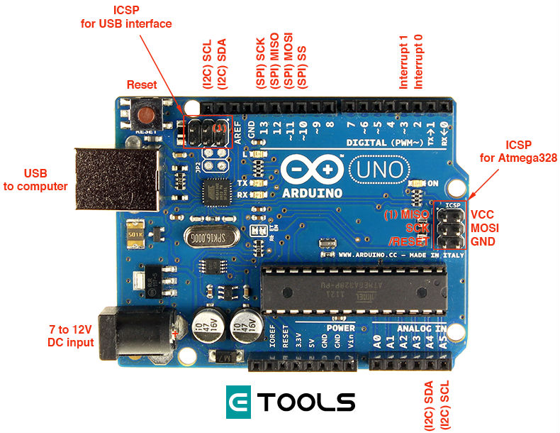
This is the ATtiny pinout
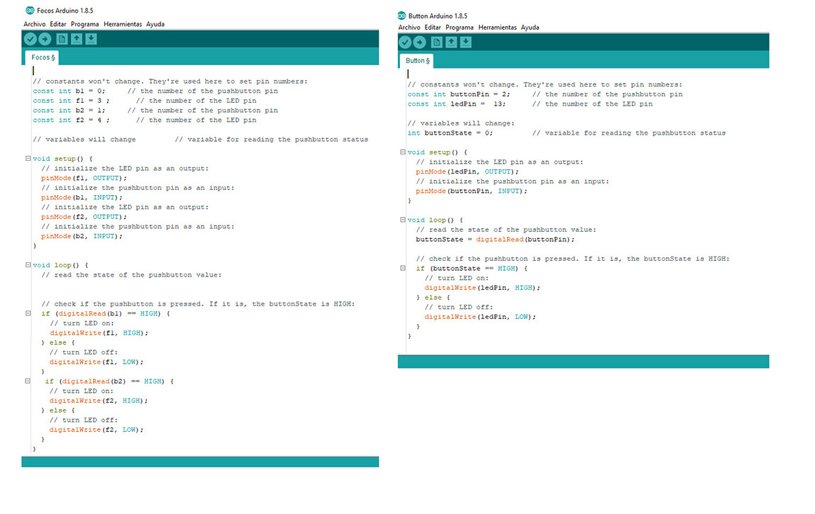
Above you can see both my code and the Arduino example I used to program a working button. My code is in the left side and the example is on the right. The main difference is that my code is made to turn on two light bulbs and it also has two buttons one for each.
To know which pin in the Attiny corresponds to the Arduino IDE pin number it is necessary to use the data sheet, there it explains what each side of the ATtiny does, and you just have to link that part to its correspondent part in the pins (you already now what each pin does by looking at the Arduino layout):
Click on the image
to download file