5
Electronics production
What I learned: I learned to weld a preset circuit, using the Mini CNC Desktop Mill to make the PCB with UBUNTU.
Sources and inspiration used:
I downloaded the files from Brian: http://fab.cba.mit.edu/classes/863.16/doc/projects/ftsmin/index.html
Software Installation for Windows tutorial: http://fab.cba.mit.edu/classes/863.16/doc/projects/ftsmin/windows_avr.html
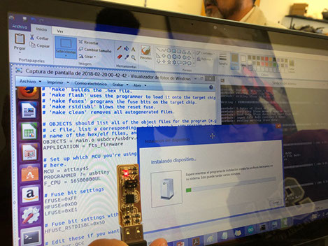
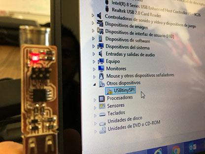
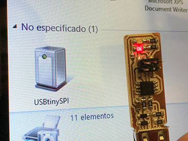
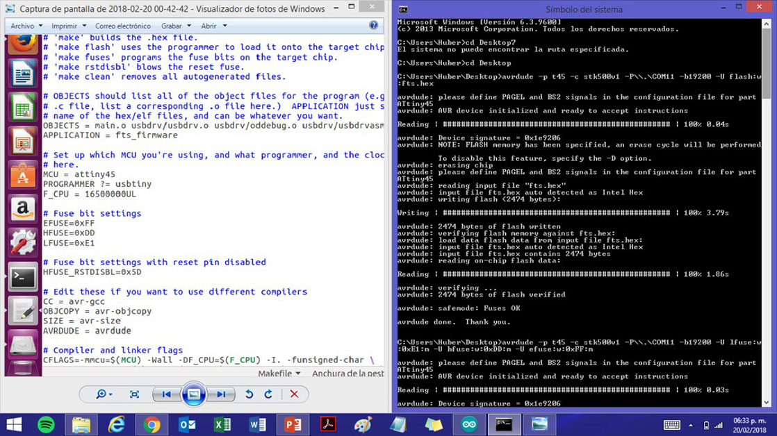
What I did: I started by installing the softwares needed yo make the USB work. I installed the Amet GNU Toolchainfrom Atmel's site. The file where extracted from "Programm Files". Afterwards I installed GNU Make and used the default location for the installation. I also downloaded Avrdud and I updated my PATH by going to Control Panel, advanced system settings and selecting the tormentor variables button. Afterwards I installed the drivers for my programmer, the first time I tried to do this, my USB wasn't detected. After doing that step I checked sanity by using Git Bash, to make sure that the commands that were installed worked the right way. My computer didn't recognize the USB, so I used another computer with Linux and followed the instructions in the tutorial. As the tutorial directed, I connected the programmer to the ISP header on the board. Then I ran make flash. And program its flash memory with the contents of the .hex file that was downloaded. Then the configuration fuses were set.It was ran the make fuses command. Then I tested the USB usability in Windows.
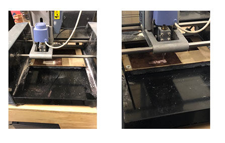
What I did: The first thing I did was download the model from Brian's link http://fab.cba.mit.edu/classes/863.16/doc/projects/ftsmin/index.html Subsequently I milled the PCB using those files. First the circuit was milled and then the board was cut using the milling cutter.
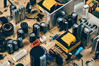
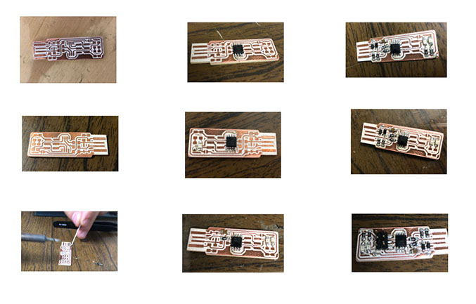
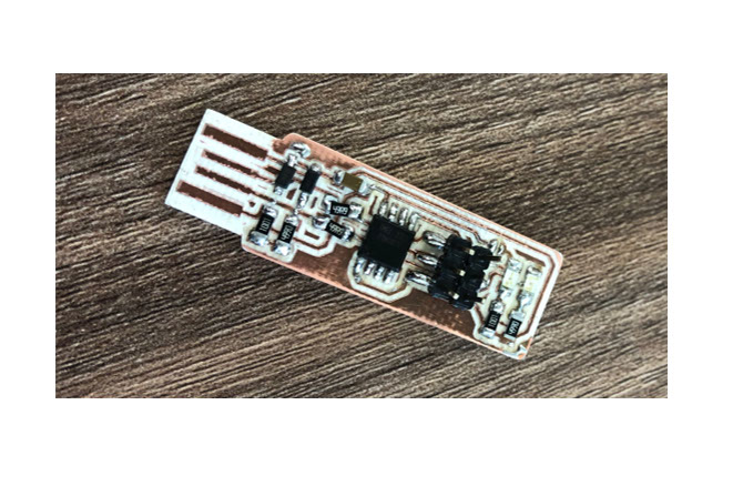
By having the board I started sanding the piece, and removing the unnecessary parts. Then I began to solder the components, I used tongs, flux paste (when my welding was too much), and soldering iron.The process is thorough and much attention must be paid to the way in which the components are placed. First the base is heated, then a bit of solder is placed, which is then reheated to put the component on it. As a group we characterized the specifications of the PCB production process. We tested the board with Brians model, and it turned out quite good.
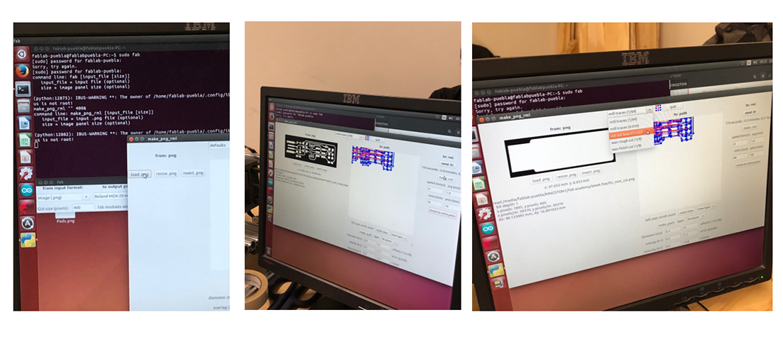
The above is done to ensure that the component will not move when welding its other parts, that step is only done when placing the component for the first time on the board. Once the component has been placed, on the one hand, the other side can be welded with a quick touch so as not to burn the pieces.The PNG obtained are linked to a physical plate. That is to say, that the parameters that I used in the machine are. On the other hand, the steps to follow to configure it to make the prints are. The tools that were used to create it, that is, what type of engraver and cutter are the mini CNC Desktop Mill Modela Roland, and I ran the Modela with the Fab Modils that run in Ubuntu. To beging I had to download the image with the circuit to cut it in the board. Then I milled the PCB using the engraver tool and then I used the milling cuter. Once I had the board I started to solder it to its components, I sued tweezers, soldering ion and fux paste. In the part regarding programming I used an arduino as a programmer to program the programmer.
The parameters used to engrave are: mill traces (1/64);the path was made in 3Dplane with a 0.4 mm diamater, 2 offsests, overlap of 0.5, error 1.1 pikxels,intensity of 0.5 and -0.1 y z (mm). The speed in mm/s is 2, the jog also in mm is 1. On the othe hand, to cut both the holes as the card i used the cut out board (1/32) option with a path type of 3D rough, diameter in mm of 08, 1 offset, 0.5 overlap, 1.1 error in pikxels, top and bot intensity of 0.5, top of z in -06 and bot of z in -1.75, the cut depth in mm is of 0.6
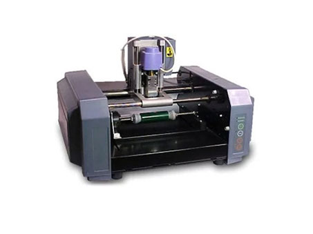
To create the PCB I used the Mini CNC Desktop Mill Modela Roland, you cna find a picture of it below. I ran the modela with the Fab Moduls running in Ubunto.
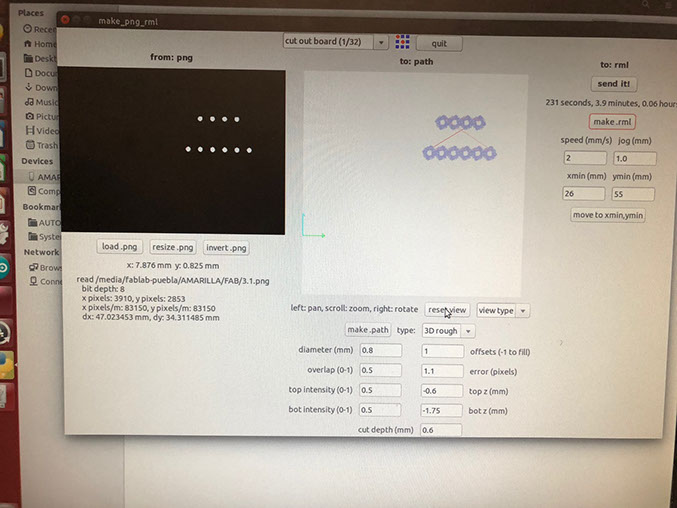
The image to the left is an example to show what each part of the software does.
I had to choose the diameter. The offsets is how many times it passes through the same place. The overlap is the distance between one and another time that the machine passes through a place. The error must not be neither to big nor too small.
The x and y min is the place where the tool starts to work.
It is important to make.rml before sending the piece to be cut.
Set the origin, click on make.path and then on make.rml, you'll get a path preview and the time remaining.
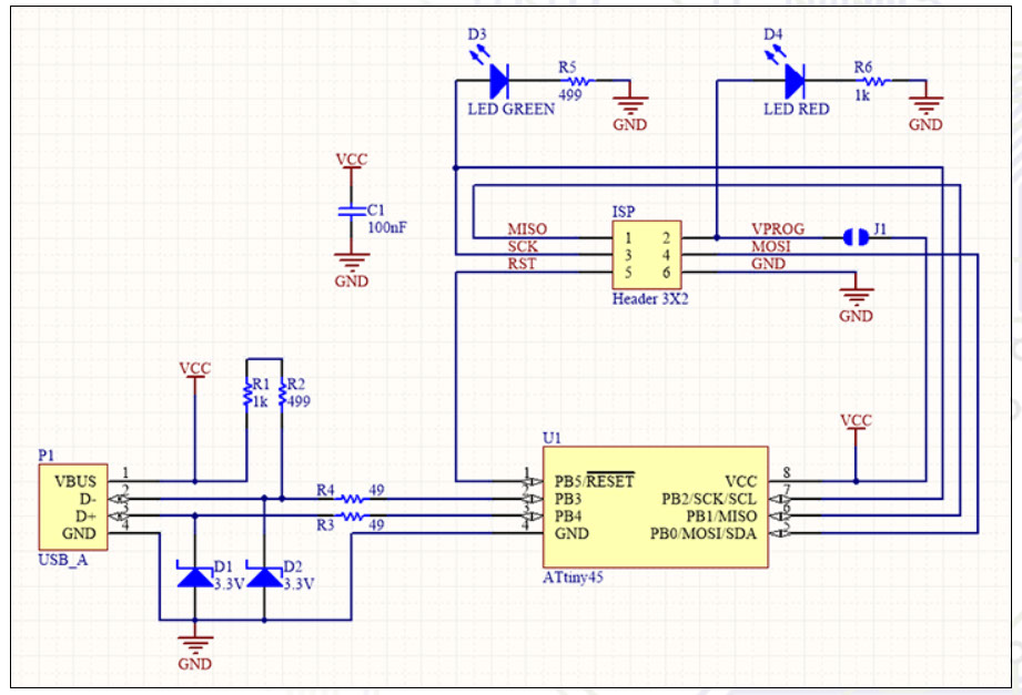
The components needed are:
Phenolic plate
1x ATtiny45 or ATtiny85
2x 1kΩ resistors
2x 499Ω resistors
2x 49Ω resistors
2x 3.3v zener diodes
1x red LED
1x green LED
1x 100nF capacitor
1x 2x3 pin header
Parameters: speed 3 mm/s and the diameter is 0.3 mm.
For cutting the perimeter I used 2 mm/s for speed and I change the diameter of the tool to 0.8 mm.
Click on the images
to download .png files
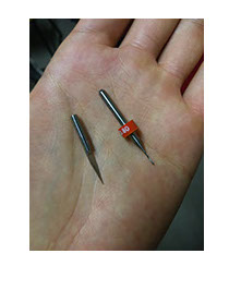
Engraving tool (left), cutting tool (right)
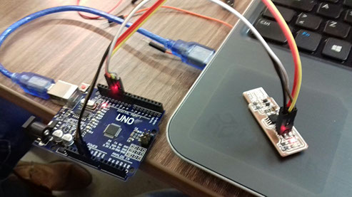
I followed Brian's tutorial for the programes (link is below). When I tried to install the software or Windows (link is also below), I had trouble. I did install GIT, I had no trouble installing the Atmel GNU Toolchain, I succesfully installed GNU Make, then I installed avrdude and updated my PATH, but I couldn't install the drivers for my programmer in my computer. After trying several times, I was able to d it in another computer that ran with Linux (as shown in the pictures above). Then I used an arduino UNO for programming so first I upload the arduino ISP example to the board, then we can use it as our programmer. I used Brian's Makefile. The pins used in Arduino Uno were
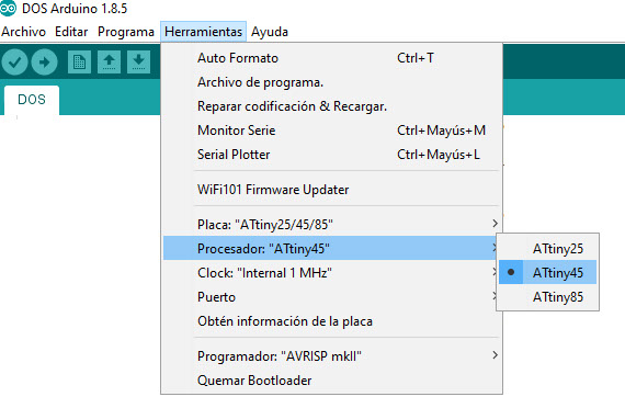
-11, 12, 13, 5V RST and GDN I made those connections to MISO, MOSI, SCK, VPROG, and RST, GND. In this case, the Makefile, by default, assumes that I'm going to use a programmer in the usbtiny family (which I am). The Arduino must be programmed so it can fit with the programmer you'll use. You just have to select in the software which plaque and processor you'll be using and then code. Once you're done you verify the code and upleade it from CMS.
Brian's Altium source files are available here
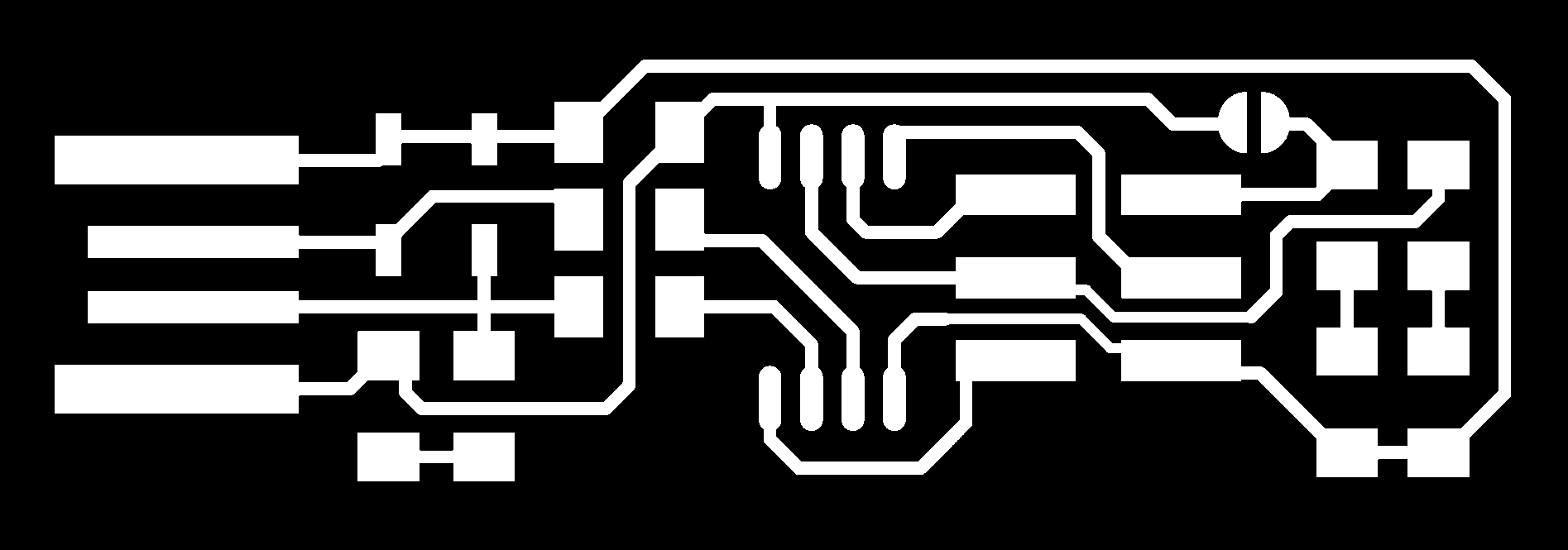
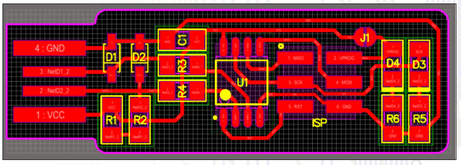
Below you can see where each component goes in Brian's design. There's also a link to the files.
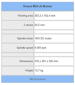
Click on the image to download PDF with Modela specifications
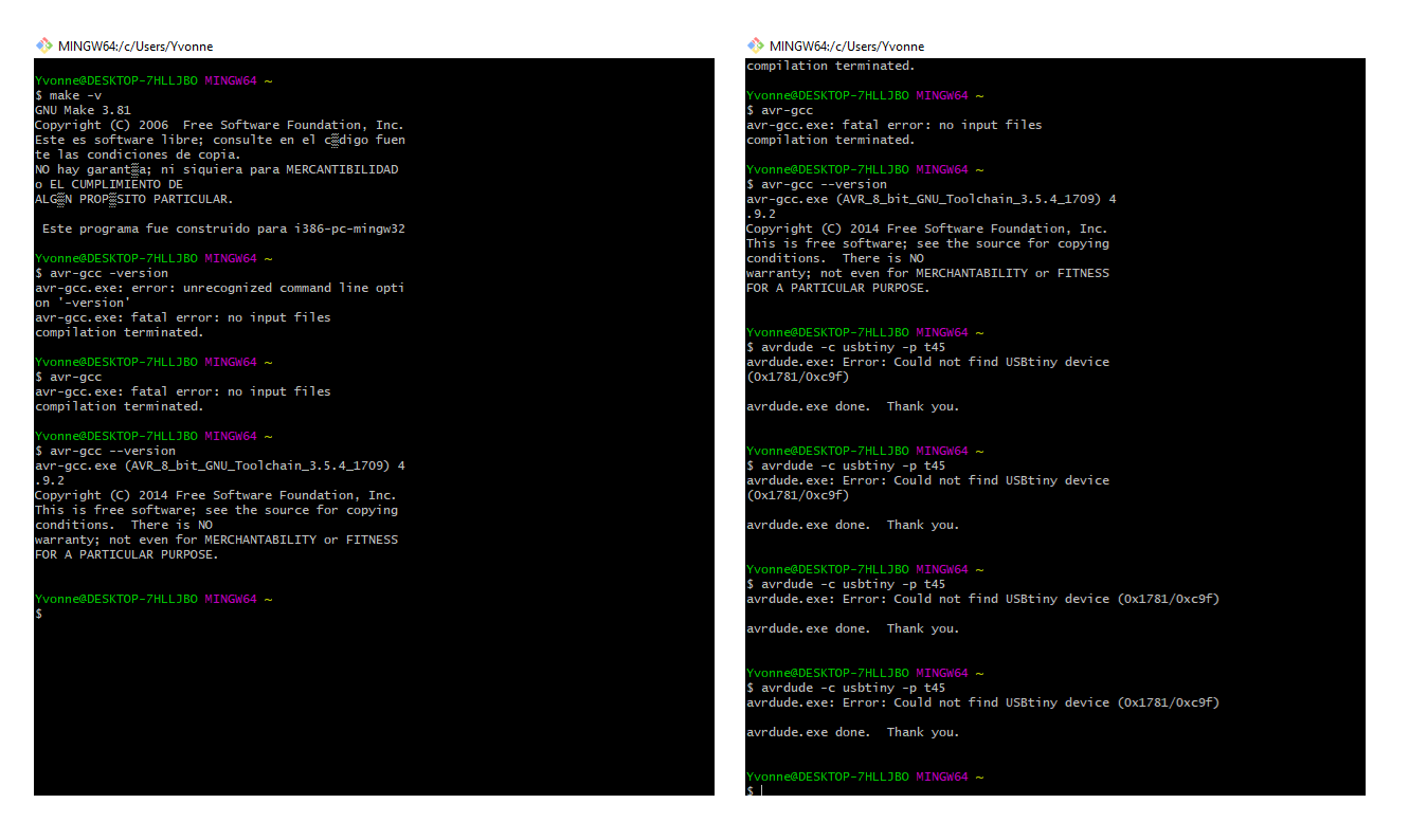
Note: I tried again to download the program to program my circuit in my own PC but I wasn't able to. I still gest stuck-when I try to run the program Zadig. It just doesn't display the driver want to install. I don't know what the problem is, because I could prgramm it in a PC that runs LINUX.