8
Computer- controlled machining
What I learned: How to use a computer-controlled cutting machine to make something big.
Sources and inspiration used:
Tree coat rack image: http://houykdd.over-blog.com/2014/05/free-standing-tree-coat-rack.html
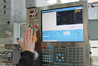
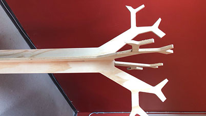
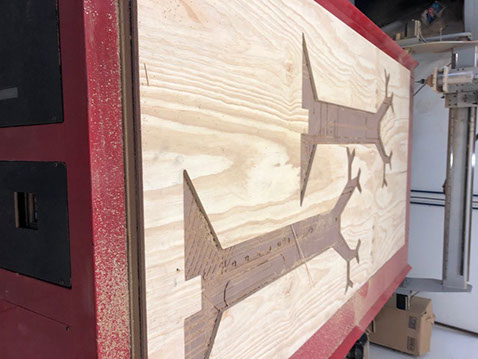
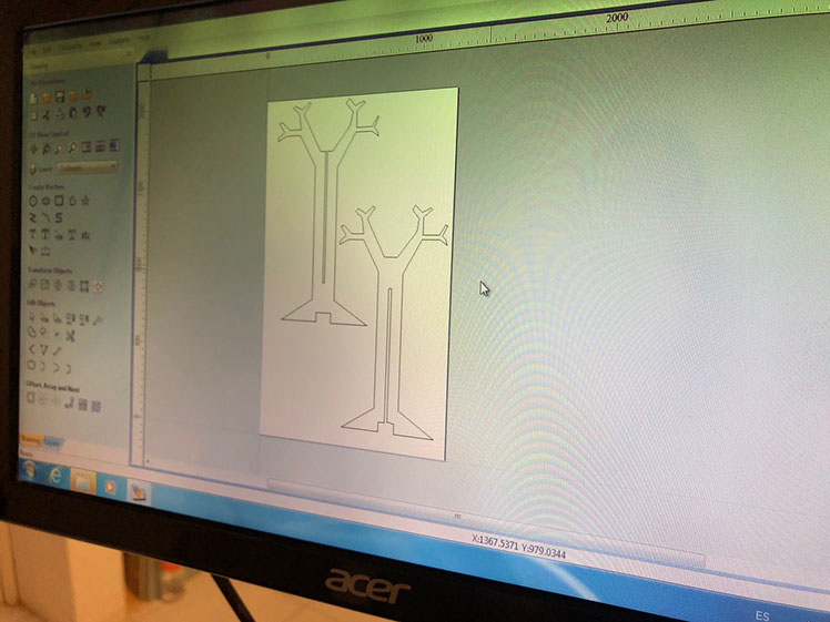
What I did: I decided to make a coat rack. The rack is inspired by the shape of a tree. It is twice the same figure; the difference is the position of the slot in each part so that it can be assembled. I searched on the Internet for different hangers with a tree shape to inspire me in the design. Then I draw it in Auto Cad, taking into account the measurements of the table with which I was going to work. The measures were 1.20 by 1.40 meters. I adjusted the silhouettes of the trees within those measurements so that they fit correctly. Before I started cutting my coat rack, we made a quick test runout to learn the alignment, speeds, feeds, and toolpaths of the machine you can see that in the pictures below.
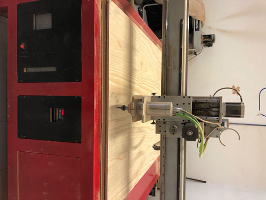
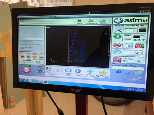


Once the drawing was finished, I learned how to use the Aspire software. I imported the file to the software. The router used is an ASIMA one. It is a Router CNC Router AR-3005 and its specs are:
Useful area: 1.52 x 3.10 x 0.15 m
Outside area: 3.76 x 2.40 x 1.80 m
Accuracy: 0.10 mm
Cutting Motor: Spindle
Vel. Max. Mov .: 20,000 mm / min
Vel. Max. Cut: 13,000 mm / min
Motor features:
Power: 3 1/4 HP
Power: 120 VAC @ 22Amp
Speed: Variable
It represents a lower initial investment allowing you to work with a wide range of materials.
Spindle: water cooled
Ideal for continuous use in medium productions of 2 work shifts.
Characteristics:
Power: 3 HP
Power: Biphasic 220 V AC @ 22Amp
Speed: Variable
Precision bearings
Less operation noise
I used Aspire as gcode generator, and te ASIMA software to upload it to the machine. And
Once it was cut, it turned out that my coat rack was a little loose, however, it remains standing and it can hold the objects that are hang from it.
I intend to improve the design and correct the measurement so that it is not loose. I also want to arch the trunk of the tree a little to improve the aesthetics and not l, so it doesn’t look so straight. I also intend to make the slots shorter, placing them only in the upper part of the tree (there’s no need for them to go all the way down).
Sadly as I already said my coat rack is a bit loose, that is because I made the middle cut in both trees and I should have only made it in one, next time I make something big I'll keep that in mind.
Click on the image
to download file
Click here to to download dxf. file
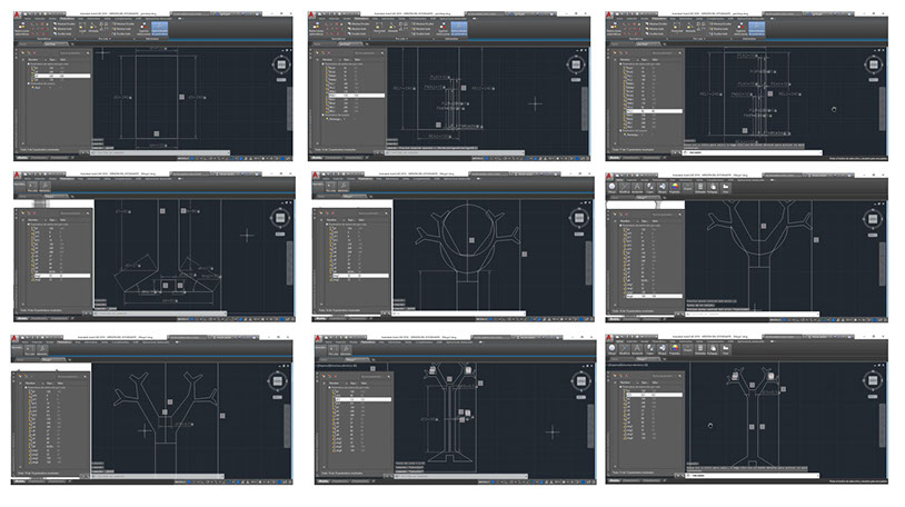
I also checked that all the lines were linked and if they were not, I used the tool to make sure that they all touched. I also had to scale the trees a bit. On the other hand, I filled out the necessary data in the software window indicating the size of the table, since it is the area where it is made, and the thickness of the table, which in this case was 15 millimeters.
I was recommended to add dog bones, so I added one to each tree to ensure the assembly. A dogbone is the method most used for routing inner pads, place a via at the center of 4 adjacent pads, such that a trace from one of the pads can pass to another signal or plane layer on the PCB and then route outward. To do that create fillets in edit object menu, and then click in the option dogbones fillet, select the radius and click in the corners needed to convert them into dogbones.
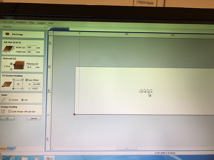
I also had to consider the diameter of the tool which is 6 millimeters, and the speed. It is important to note that my file was made in Autocad, but the router uses Aspire so I ad to export the file so the software could read it. To do that first I created a new file. First I had to define the Job setup, specifying the Job Size in X and Y (I used the measures for the triply). I also had to define the material (that is Z), and in this case it was 15 mm. Afterwards decide the XY Datum position. To set the machine to the origin, I do it manually by clicking in the arrows in the interfase of the software to set the origin (just like in the milling machine).
Then I use the import option and when I opened it. Then I imported the vector (that is the file I made as a dxf). Once I have my file imported I selected everything and then I centered in the material. But the outline was a bit rough so to make it better I needed to clean it up, by selecting the outline I used Fit Curved to Vector to make it better. I selected the straight line option. I the arcs I used circular arcs to have more rounded corners. Once I was finished with that, I used the dimensions option to resize to make sure everything fitted just fine in my material.
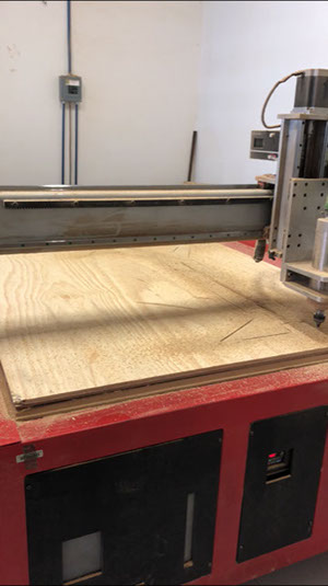
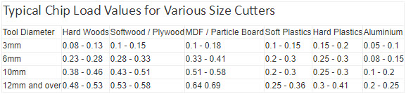
Then I sent it to get cut. But before, I placed the material in the CNC Router. I used nails to fix the wood to the panel, in the machine I had to zet the zero points moving the axs and setting it to zero to the point I wanted. It is important to note that the feed rate is calculated using the following equation: Feed= N*CPT*RPM; where N is the mumber of cutting edgles, CPT is the chip load, the amount of material to be removed by each tooth of the cuter, and RPM is the speed the cutter revolves. The next table shows how to choose the value. I had to pass de G code from Aspire to the machine, and manually move the origin point to zero, to let know the machine where it should start cutting. The parameter used in this FabLab is 12,000 rpm for spindle with a 2,545 mm/min speed.
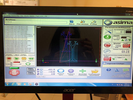
The picture to the left was taken to show better the interface of the software, but in my case I used a 15 mm material not an 18 mm one. I wanted to use a 18 mm material but we didn't have that in stock, and that's why I used 15 mm.
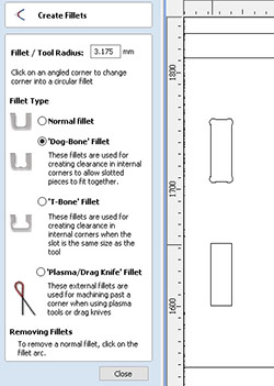
Here's an example of a dogbone in Aspire, click on the dog-bone fillet, select the radius and click in the corners that are wanted to be turned into dog bone. It is important to set the toolpath (click in the menu to the right). then edit the configuration of the tool by setting the diameter of the roo, the spinde speed , the feed rate that is the inear speed of the cutting too and the plunge rate that is the speed of where the tool will move in the z axis.