11

Input devices
What I learned:
How to measure sound by adding a sensor to a microcontroller board.
Sources and inspiration used: https://learn.adafruit.com/assets/39633
How Electret Condenser Microphone works: https://www.engineersgarage.com/insight/how-electret-condenser-microphone-works
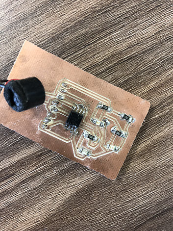
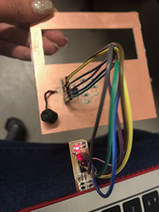
What I did: This assignment has the purpose of generating a system that allows to know if there is a noise in the environment. It consists of a card with microphone, if the microphone perceives a lot of noise the red led lights up. In case the noise is moderate, the yellow LED can be turned on and if there is no noise or this is very little, the green led will light up. The elaborated card was made with USBtiny and used inspiration from Adafruit I2S MEMS Microphone Breakout from the Adafruit page (the link is at the bottom of the page). Below you can see the components I used. I decided to use electrect instead of MEMS because I changed the code. The electret microphone is a electrostatic capacitor microphone. I only managed to turn on one Led, I hope that with more time and experience I will be able to turn on the three Leds depending on the quantity of noise. As I group we measured the analog levels as well as the digital signals in the input device. Transducers are devices which convert energy from one form to other. A microphone is a transducer which converts sound energy to electrical signals. Electret Condenser Microphone, as the name suggests is a parallel plate capacitor and works on the principle of a variable capacitance. It consists of two plates, one fixed and the other movable with a small gap between them. An electric potential charges the plate. When sound strikes the diaphragm it starts moving, thereby changing the capacitance between the plates which in turn results in a variable electric current to flow.
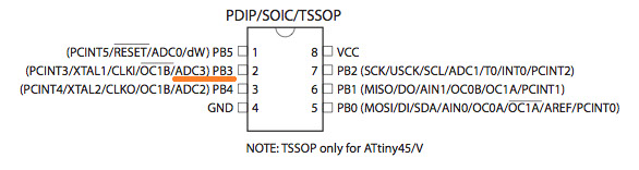
The code goes like this to turn on the Led once the microphone hears once and turn it back of once its over, iIuse pin 3 for the output and 2 for the input (I used Atiny pinout to decide where the connections to the pins should go). I wrote the code that way because I saw examples for buttons in Arduino and I tried to do it similar.
int sensorPin = A0;
int ledPin = 2;
int sensorValue = 0;
void setup() {
pinMode(ledPin, OUTPUT);
}
void loop() {
sensorValue = analogRead(sensorPin);
if (sensorValue >=400 ) To know the value it was trial and error changing the values until the led turned on
{
digitalWrite(ledPin, HIGH);
}
else
{
digitalWrite(ledPin, LOW);
}
}
Click on the image
to download file
Click on the image
to download code
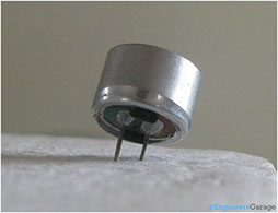
Electret

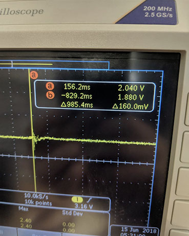
This images show how an to measure the electret values, with an osciloscope with an applause
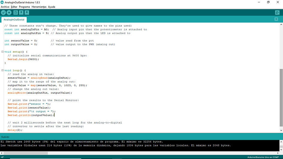
The picture shows the measurement (top right), it has a line, it has a letter A that is the point where it is and it marks 2.04 volts and the first picture is how the signal is seen and the second is how it is measured. Below is the code made by Tom Igoe in Arduino Example used to measure the Electret.
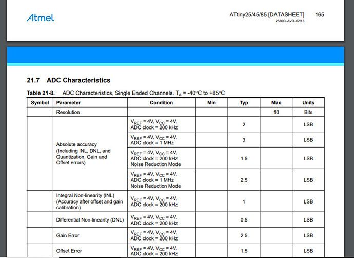
The ADC of the ATtiny is 10bits (you can find that information in the Datasheet). Which means that it will measure it in a range of 0 to 1023 for a total of 1024. The maximum value is 5 therefore 5 is worth 1023. Then as a rule of three it is necessary to know how much is 2.04, then it is 2.04 x10²³ between 5 that gives 416.37 I chose 400 because it is a round number below peak.
Click on the image
to download code
Click on the image
to download file
I used the code above to test the value of the Electrec, you can see me testing in the first video below. And in the next video I'm analyzing how to measure tha values.