
Our local instructor this week, Eino Antikainen, guided us through the process of preparing a 3D design in Fusion 360 for cutting in the CNC router. Eino explained us the how (how to generate the toolpath and export the values) and the why (the meaning of some of the values we needed to choose). He also showed us how to prepare the machine and cut our design safely.
To Do
- Design something big
- Prepare the 3d model to get the info the cnc router needs: toolpaths
- Cut the Big Thing.
- Group work
The "Doing"
Design Something Big
For this week, my plan is to design something big for the final project, based on the sketches I made last week in the final project evolution.
I want to design a thin wardrobe that has
- A middle piece with a place to put a board with the UI design. The board can be still similar to the one designed in
- Room on the back to put the electronics (should be accessible though)
- Room on the front for the "clothes" ...
- Round corners
As I want rounded corners, my plan is to create layers to give volume to the piece. I have used Fusion 360, and the final result looks like

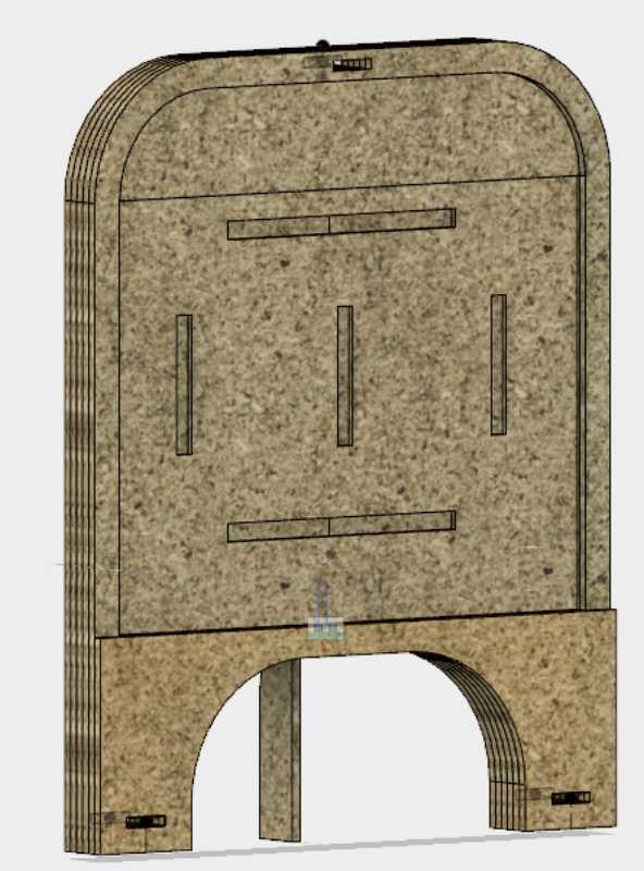


The design summary is:
- Total of 6 layers:
- Front part: with doors to open
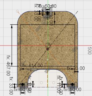
- Middle part: with a pocket to hold the UI board and holes to allow the cables to go through
- Back part: with doors to access the electronics
- two extra layers between back and middle parts: to allow room for electronics (around 2cm should be enough)
- one extra layer between front and middle parts: to allow room to whatever the user interface may have
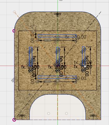
- Holes go through all the pieces to pressfit a holder piece
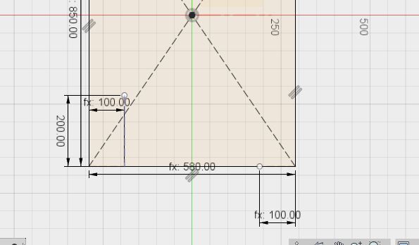
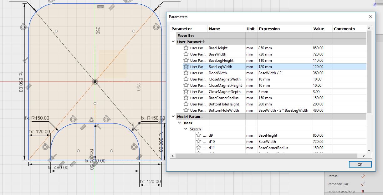
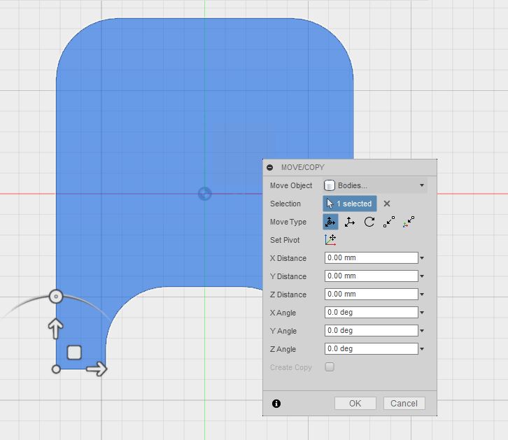
I create a new model and create the basic sketch for the whole design


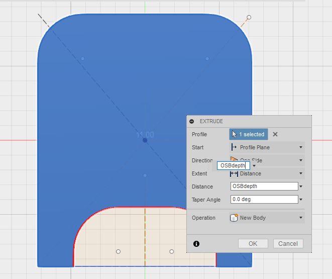
I extruded the sketch, and then created the rest of the components and copy the body to those, as I did on assignment 4

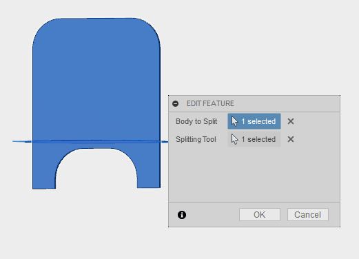
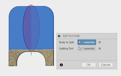
I decided later to attach all the different layers with press fit technique, using smaller pieces that would go through the layers. So I had to play a bit with the timeline, to go to the correct place to do the sketch so it would be applied to all the components

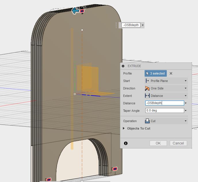
Other sketches needed for the design are in the middle part, to make room to the future UI and holes to allow to pass the electronics to the back part. Both sketches are followed by extrude.
Also, the front part needs some cuts to get the doors:
Get the toolpath
Preparing the software
We need to download two files
-
The CAM post processor file for Fusion360: FabLabCNC.cps
- This will be used when creating the
Post Process, so when creating the file for the cnc machine - It is necessary to copy this to
configuration folderfrom thePost Processprompt as shown later on the text
- This will be used when creating the
-
The file for tooling values for different routing bits: FABLAB ROUTERI TOOLS 2018-2.hsmlib
- This will be used when selecting the
Toolwhen pockets and contours - It is possible to import this library the first time you need to select a tool as shown later on the text
- This will be used when selecting the
Preparing the model
Once the model is ready, we need to place all the pieces in the same plane to create the toolpath. These are the steps I followed
- I created two new components in my model and I copied all the different components of the model in them
- 3D model, will hold the components as they are in the design
- CAM, to create the version for the cnc machine (all the pieces in the same plane)
- I created two new components to emulate the boards I am using: 260x120cm (I assign them the texture of the material I will use in this assignment)
- I already had an idea of how to organize the pieces in the boards, so I knew I needed two
-
I align those components to the Y=0 plane with
Modify > Alignsetting thefromto the piece to be align and theToto the plane, always getting the same face -
I start to align all the different components the same way, taking into account that the drill size will be 8mm so I leave enough space between the different pieces.
Modify > Alignsetting thefromto the piece to be align and theToto the plane, always getting the same face
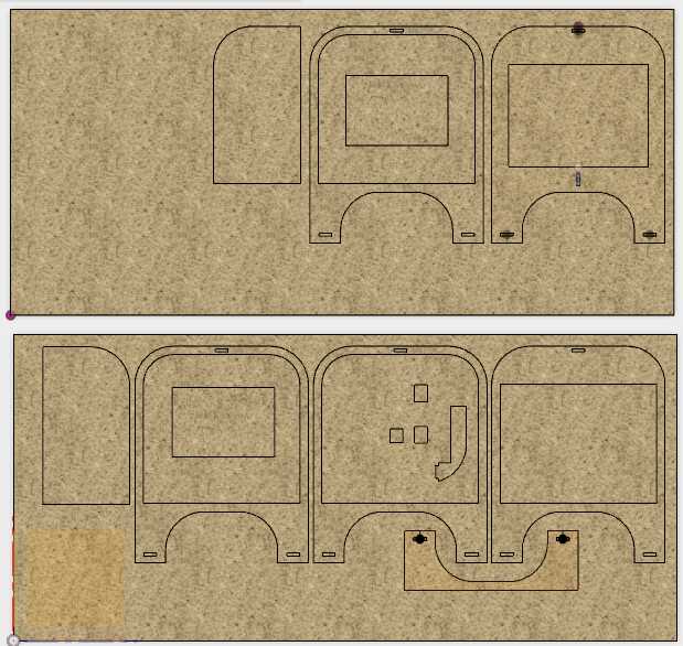 Top view of all the components placed in the same plane
Create the toolpaths
These are the steps I have followed in Fusion 360
- Switch to the
CAMworkspace - You need to create a new setup per layout to cut. So I need two.
Setup > New setup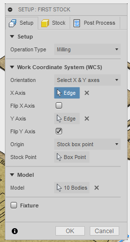 new setup menu prompt
- setup tab
- Setup the
Operation typeto Milling - Setup the
Work Coordinate SystemSetting theorientationas Select X & Y axes, and the origo
- Setup the
- stock tab
- Setup stock values to 0mm
- setup tab
- Create a
2D > 2D Pocketper design / set of designs that need pockets, that is, holes of a determined depth (TO be continued)
setup tab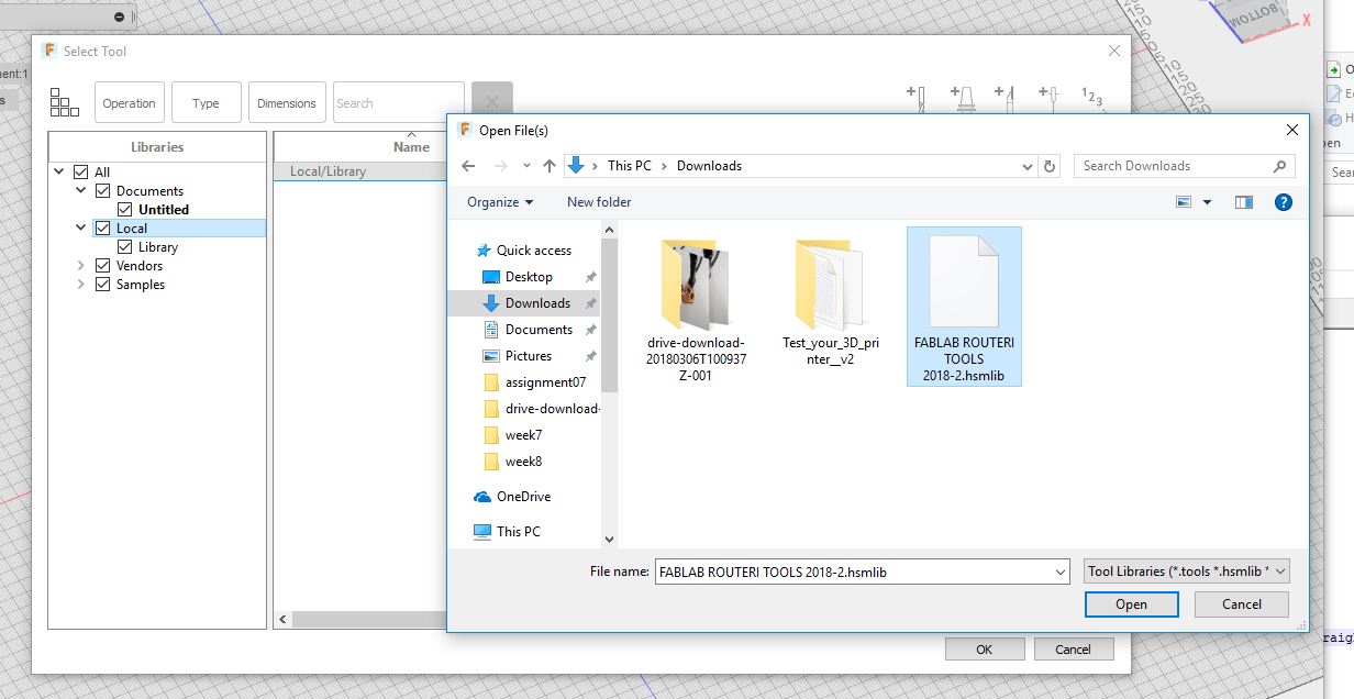
setup tab >select toolImport library to local. Just the first time you select the tool!
setup tab >select toolI will use 8mm flat bitsetup tabTool > Selectto select the tool- Rest of values are loaded when selecting the tool
setup tab > Tool > Select- Top Figure: Menu window to select the library downloaded before as explained in the text above
- Bottom Figure: List of available tools in the library
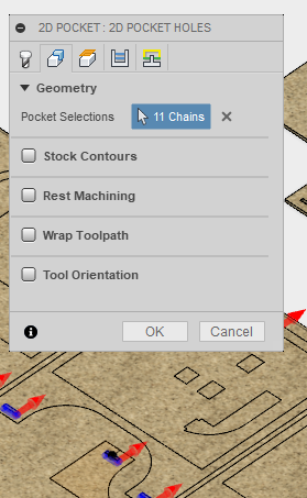
geometry tabgeometry tabPocket Selections: Select all the chains that will be included in the current pocket definition. It is better if there are similar
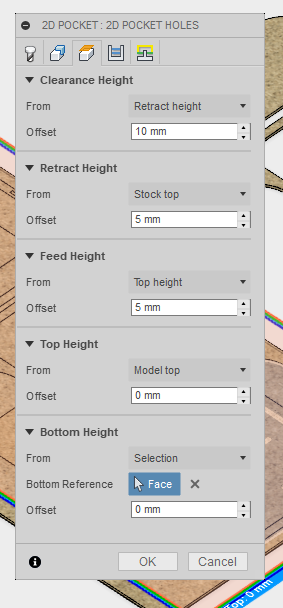
heights tabHeights tab.- It is important to define correctly all the reference heights for the machine. Go from bottom to top
Bottom Height: Sets the height that describes the top of the cut. In the picture, it is set as an offset of 0mm from the selected face, which was the bottom face.Top Height: Sets the height that describes the top of the cut. In the picture it is defined as an offset of 0mm from the Model TopFeed Height: Sets the height that the tool rapids to before changing to the feed/plunge rate to enter the partRetract Height: Sets the height that the tool moves up to before the next cutting passClearance Height: First height the tool rapids to on its way to the start of the tool path
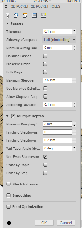
passes tabpasses tab- Multiple depths & Use Even Stepdowns
- Uncheck Stock TO leave: We do not want any stock left

linking tab- Uncheck Lead-In and Lead-Out
- Ramp set to Plunge
linking tab - Create a
2D > 2D Contourper design / set of designs that need to be cut (TO be continued)
setup tabsetuptab >select toolImport library to local. Just the first time you select the tool!setuptab >select toolI will use 8mm flat bitsetup tabTool > Selectto select the tool- Values are loaded when selecting the tool
setup tab > Tool > Select- Top Figure. Menu window to select the library
- Bottom Figure. List of available tools in the library
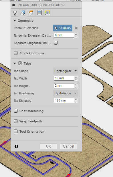
geometry tabgeometry tab- Click on the Chains to be cut
- Beware of the red arrow (see figure): with the red arrow you select on which side of the chain the bit will cut: outer contour or inner contour. Check you have it correct!
- Check tabs. Tabs are small pieces that will remain holding the piece you are cutting to the board. These are needed because the tool vibrates when cutting and the pieces may move. If this happens
- The bit may cut your piece in undesirable places
- Small pieces may be thrown away in any direction
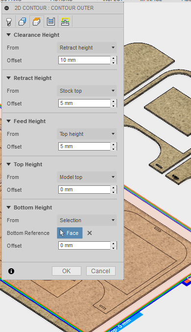
heights tabHeights tab.- It is important to define correctly all the reference heights for the machine. Go from bottom to top
Bottom Height: Sets the height that describes the top of the cut. In the picture, it is set as an offset of 0mm from the selected face, which was the bottom face.Top Height: Sets the height that describes the top of the cut. In the picture it is defined as an offset of 0mm from the Model TopFeed Height: Sets the height that the tool rapids to before changing to the feed/plunge rate to enter the partRetract Height: Sets the height that the tool moves up to before the next cutting passClearance Height: First height the tool rapids to on its way to the start of the tool path
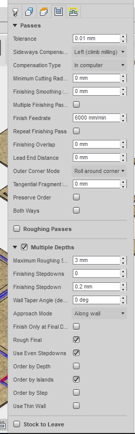
passes tabpasses tab- Multiple depths & Use Even Stepdowns
- Uncheck Stock TO leave : We do not want any stock left
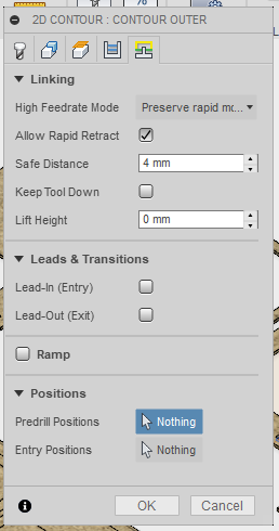
linking tablinking tab- Uncheck Lead-In and Lead-Out
- Ramp set to Plunge
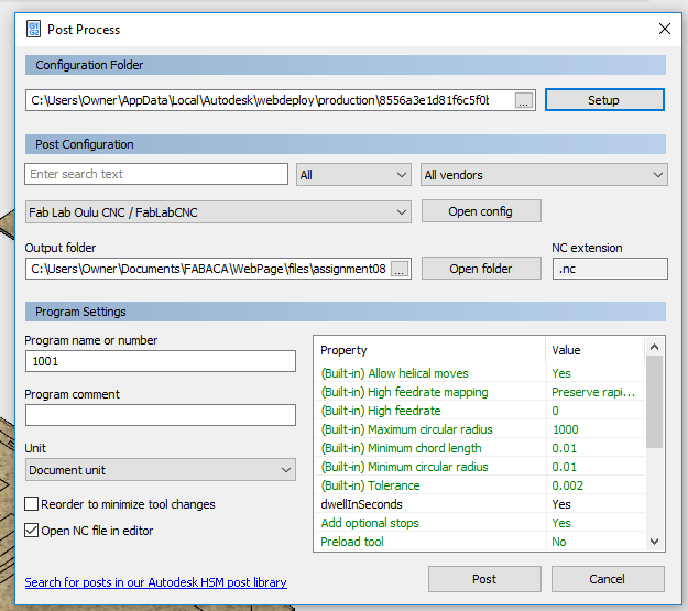
Actions > Post process window.The Post Configuration file that is used to translate the Fusion 360 dialect into the dialect the CNC machine understands was downloaded as indicated before. This script must be stored in Fusion Configuration Folder as shown bellow. Then, by clicking Post the nc file will be generated and stored in the output folder.
Cut the Big Thing
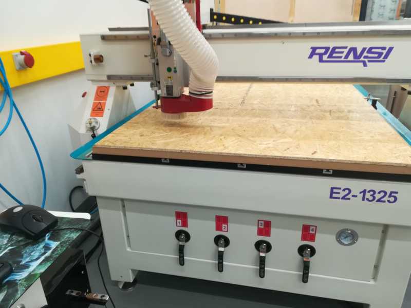
The machine


Safety
Always:
- Go with someone
- Use protective googles
- Do not mess around the machine when it is working
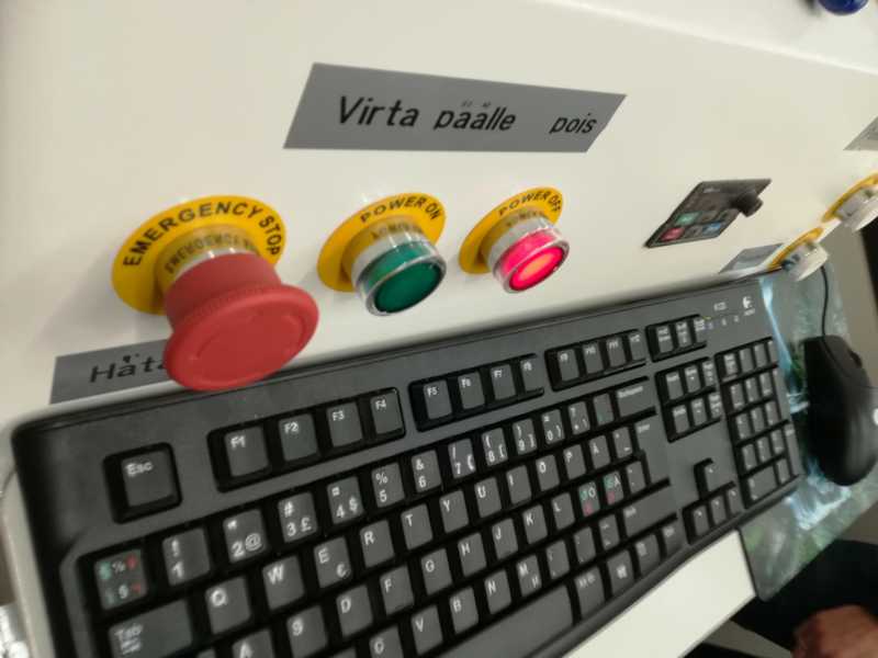
- Do not start it until you know how to stop it
- Do not leave the machine working without supervision
Cutting
The process
- Open the computer
The software first asks to set the machine zero (mechanical origin). To do so, in the prompt just pressAll Axes, and the machine does it automatically Set Mechanical Origin
 - Put the board on the machine platform: screw it well
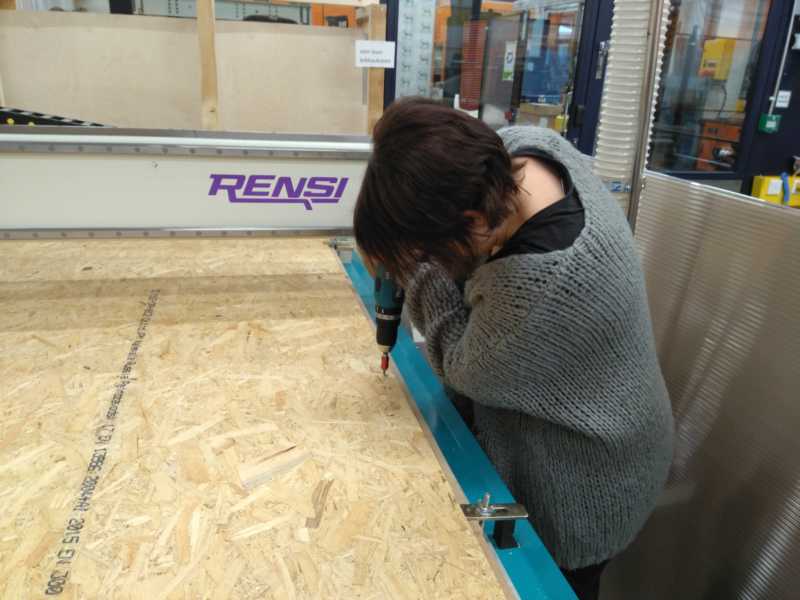 Screw the board well
 - Set the origo: You need to be sure how much material you need, and where your design starts.
You can move the header with the cursors on the screen or with the hand wheel controller. To select: on the right hand of the window, chooseManual> Jogfor screen cursors orManual > HWfor the Hand Wheel.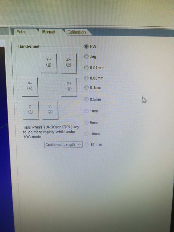 Select How to manually move the header
- Be careful with the screws!!
- the X, Y:
- just move the head with the hand wheel controller (picture bellow on the left) to the desired place
- hand wheel controller: choose the axis from the knob on the top left and move the head turning the wheel.
- desired place: in my case, the corner shown in the third picture bellow. (The same origo as when creating the toolpath)
- (beware of screws)
- and press the W. Coord. buttons corresponding to X and Y in the app in the computer.
- just move the head with the hand wheel controller (picture bellow on the left) to the desired place
- the Z:
- it is also possible to do it manually (as with X and Y), very carefully;
- but there is an automatic way also.
- You need to put the mobile calibrator (second picture bellow) just beneath the bit.
- Then, select
Operation > Mobile Calibration...and start calibration. - The bit will move down to the metal thing and detect and set the zero that way.
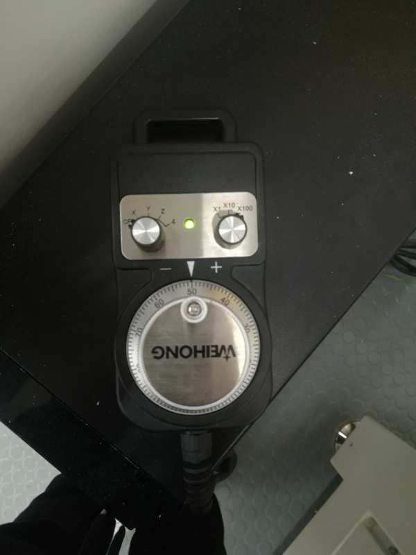 Hand wheel controller to move the head. Choose the Axis and rotate the wheel to move the head.
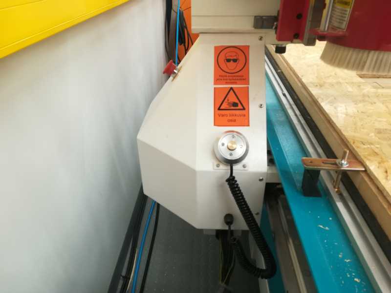 Mobile calibrator set of Z origo
 Put the piece beneath the bit
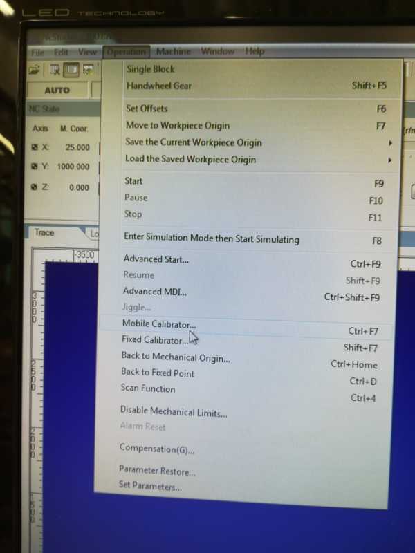 Select
Operation > Mobile calibrationand wait - Load your file (
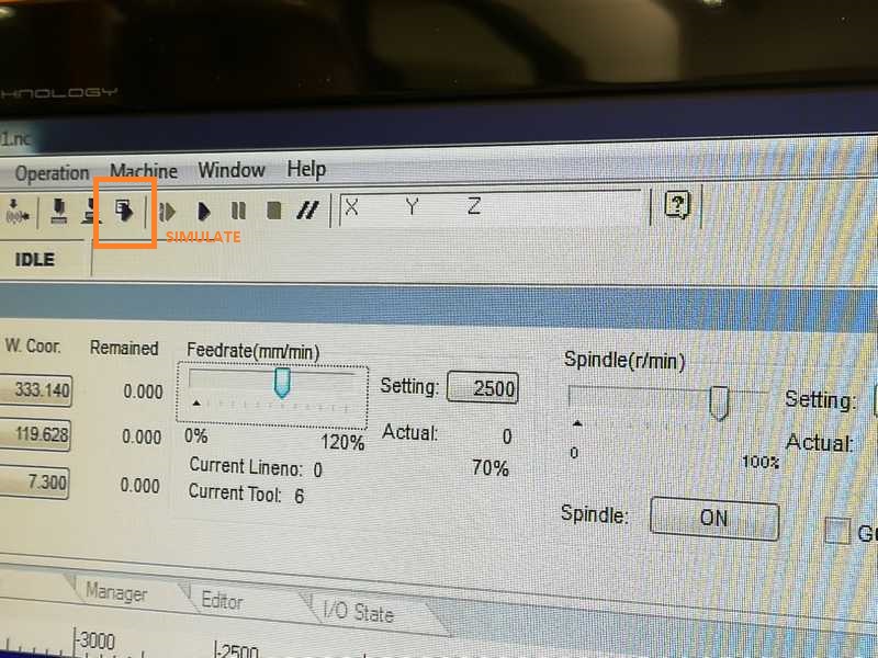
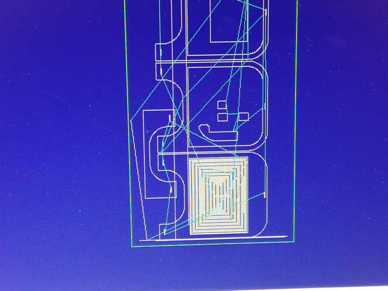
File > open and load) in the app and simulate (press button shown in picture below)- simulation will help to see if everything is ok in the board: if the design layout is as and where you were expecting
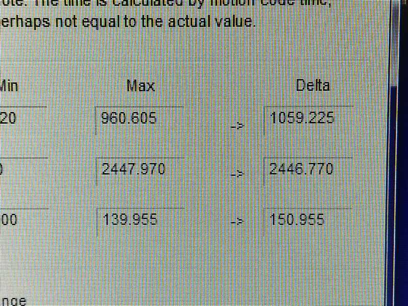
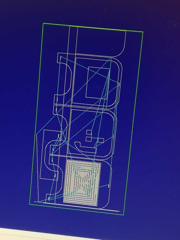
- The simulation allowed me to see that one of the layouts was exceeding the board. It was quite odd to me, as I was sure I had measured everything OK. It took a while to realize that the actual work area of the machine is smaller than the board size, possible due to this part at the back.
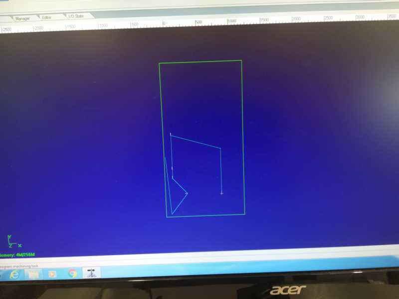
I had to reorganize the layout and I managed to fit it.
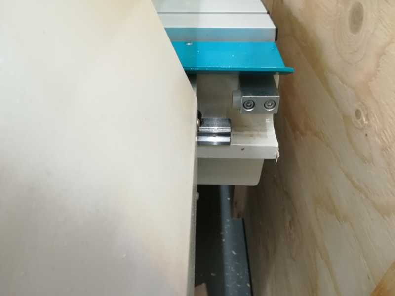
 Machine work area smaller than the board size
 The layout fits the board and it starts where expected
 -
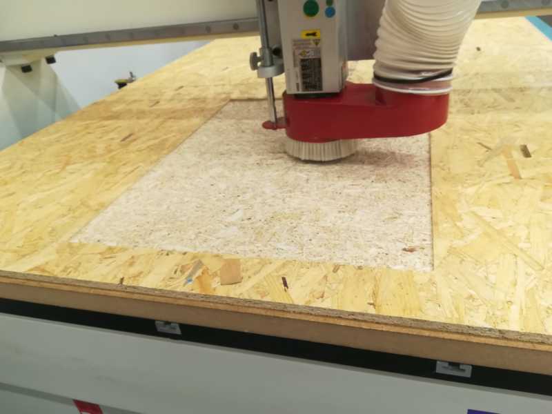
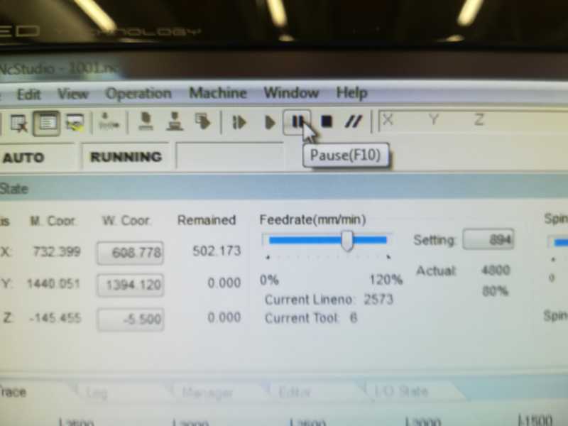
Just start the process... slowly (lower Feedrate and spindle as shown bellow)
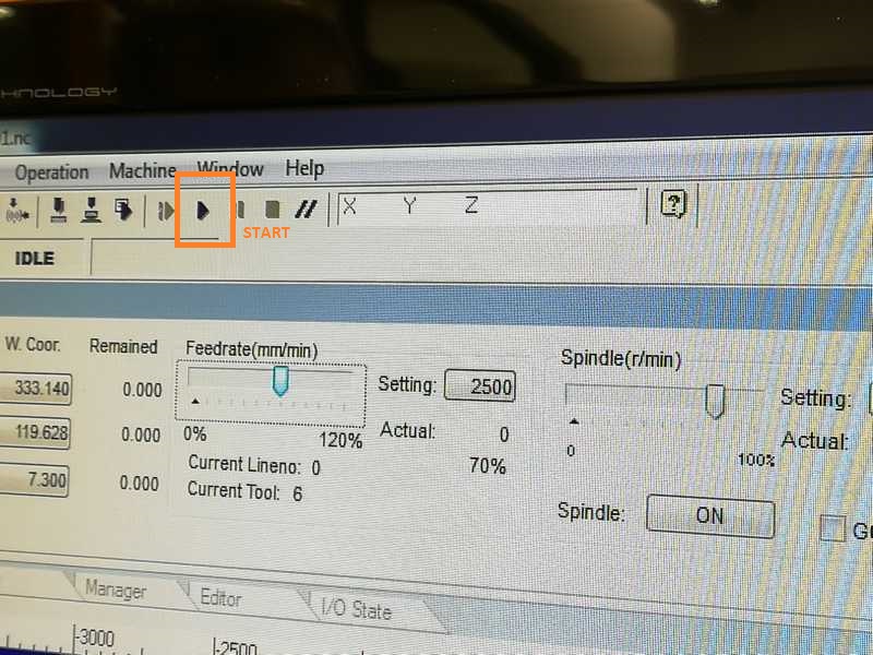 Start with a lower Feedrate and spindle
The first piece went as expected
 Simulation of first board
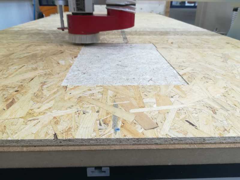
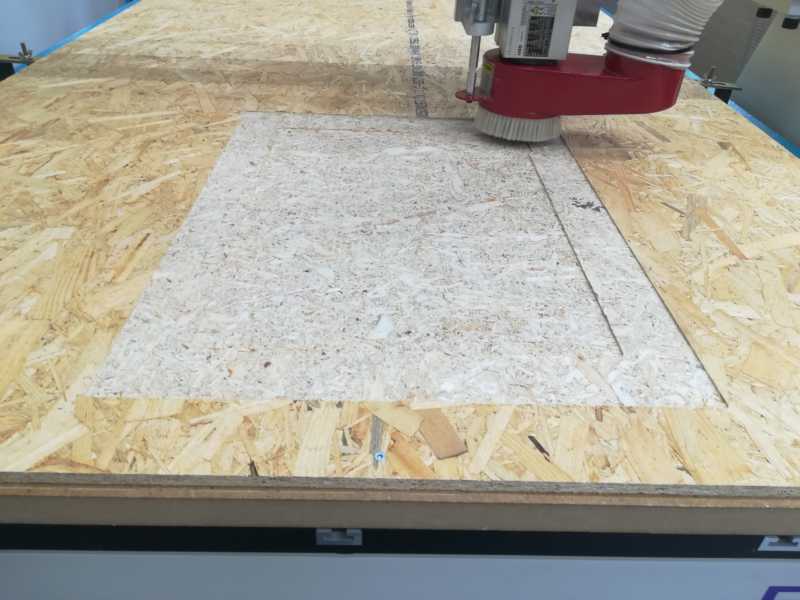
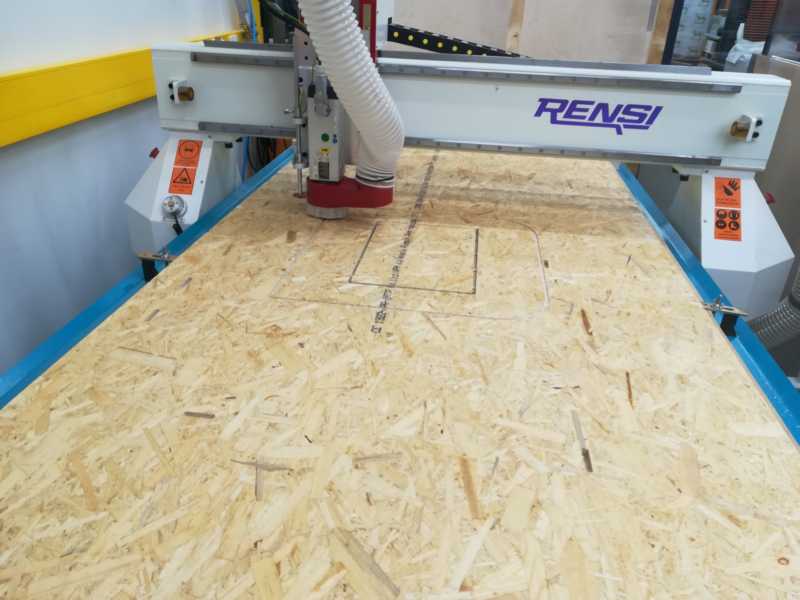 Cutting the first board
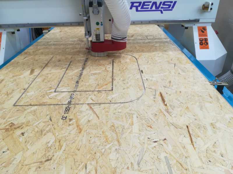 Continue cutting the first board
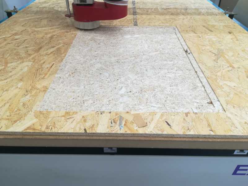
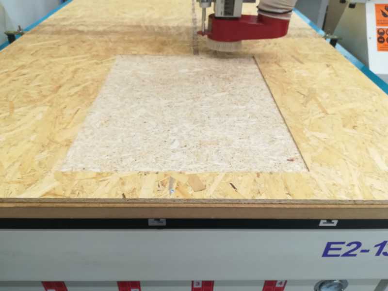
The second piece, after adjusting the layout, started well. Doing the pockets at 4mm and with the hole depth:
 Pocket toolpath


The main problem with the second board were the small pieces. Although they were cut before the bigger pieces, still the tabs I used were not enough to hold them.
As I was all the time in front of the machine, I noticed they started to move to much. I was prepared to pause the machine at any moment. Luckily, none of them flew and none of them were damaged by the bit.
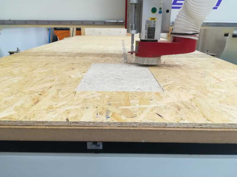
I paused the machine to remove them, before it continued cutting.
 Pause the program
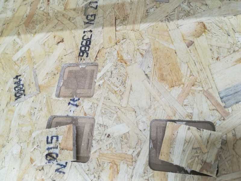 Pieces at the working area
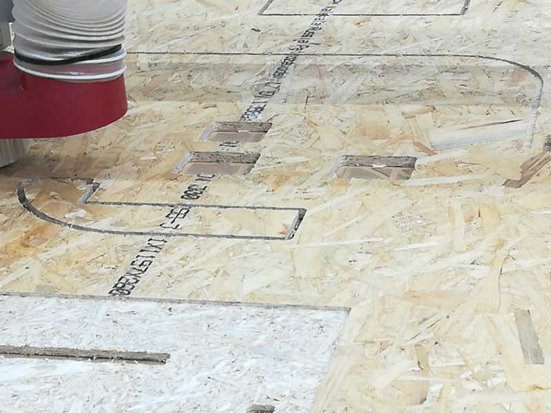 Remove the pieces from the working area before continuing
Once you are done...
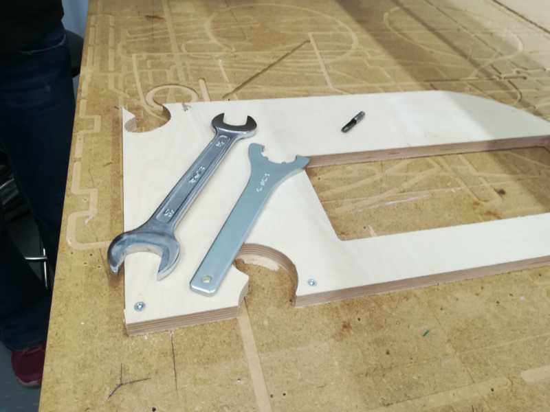
- Remove the pieces: You have to cut the tabs!
 Cut the tabs with a cutter
 - remove the remaining board from the working area
- Switch off the machine and close the app and computer
- Always clean your mess!!
- If you also have one of this....
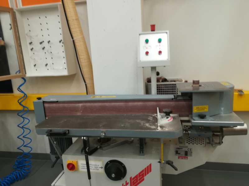 Sanding machine... use it to sand your pieces!!
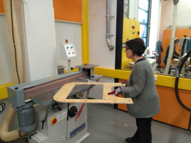 Sanding
 More sanding
 - Assemble your pieces!!!
 front no door no back
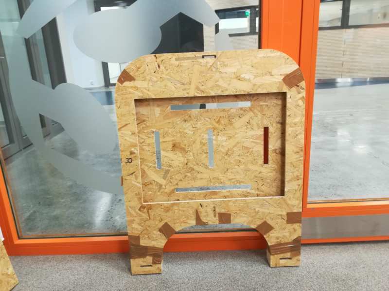 back no door no front
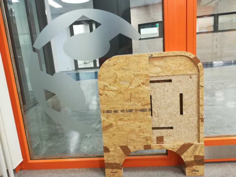 front with one door
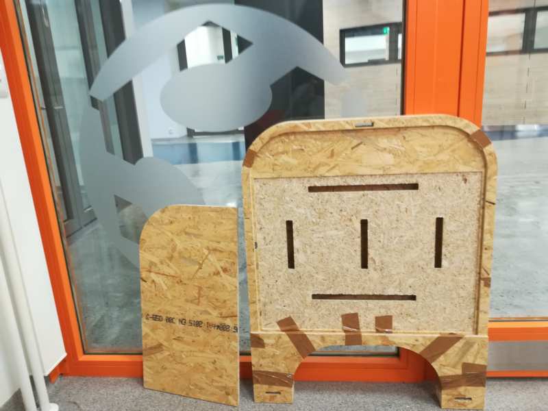 front and one door
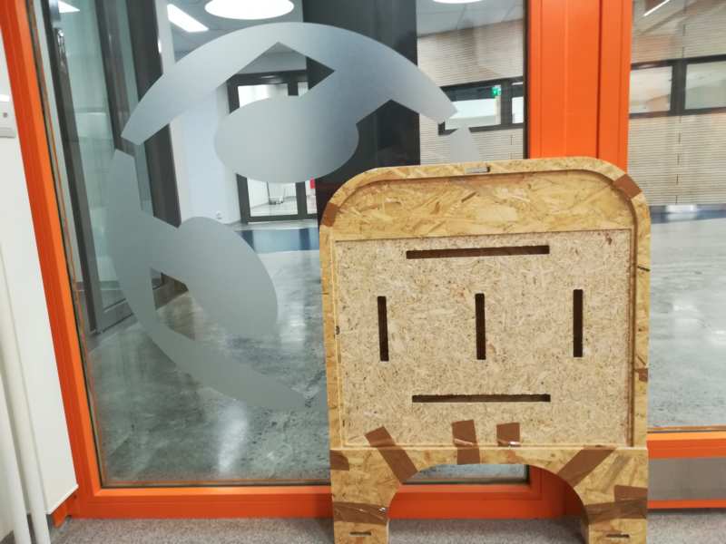 front with no door
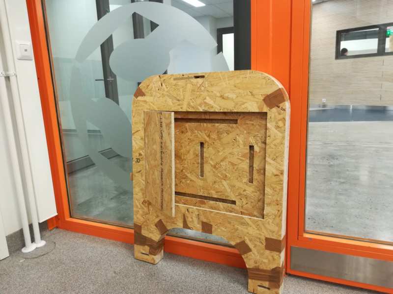 back with one door
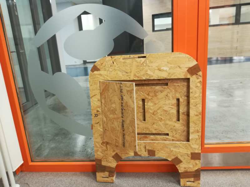 back with one door (other view)
Resources
Once done
Summary
- I have learnt to create a bit more complex design in fusion 360
- I have learn to prepare a 3d design to be cut in a cnc router: align pieces and work in CAM workspace to create toolpaths
- I have learnt to prepare a cnc router to cut a design
- I have learnt many security tips for the cnc router
Difficulties
- The design this week took a long time. I was not sure how to assemble together all the pieces. And there were many of them. Eino gave me a tip, and I could check from Kati how it worked, as she was using the same, and doing it before me
- During the design drawing, I was convinced I was doing a very parametric design. But it turned out some of the parametric measurements I was adding did not work as expected. I need to go back to that and check how to change it.
Learnings
- Smaller pieces need more tabs, or thicker ones
- The size of the board that fits the machine may differ with the working area
Tips
- Check the maximum physical size the machine fits
- Smaller pieces need more tabs, or thicker ones
Files
- nc file for board 1
- nc file for board 2
- .f3d file for wardrobe NOTE: This file contains all the designs needed (both, MODEL and CAM), but when it opens, the history line is at some point in the middle. Please, move the history line cursor to the end to see the whole design.
- .stl file for wardrobe
- .dxf file for wardrobe