For this week we have two small projects and one Group task. We need to learn to use the vinyl cutter. And we need to learn how to use the laser cutter, including some needed characterization. We have to do that characterization in groups. Our local instructor this time, Eino Antikainen, explained the basics&tips for the vinyl cutter and the two laser cutters in FabLab Oulu. He also gave some tips on how he calculated the kerf.
To Do
- cut something on the vinylcutter
- design, make, and document a parametric press-fit construction kit, accounting for the lasercutter kerf, which can be assembled in multiple ways
- characterize your lasercutter, making lasercutter test part(s), making test part(s) that vary cutting settings and dimensions(group project)
The "Doing"
Vinylcutter
It's been long since I wanted the skyline of my home city at any wall at home. So I thought this was a good opportunity to see how it would look. On the other hand, I decided to keep on using inkscape for this this task. Just because I already know it.
I started to look for some pictures. My plan was to work as in the Assignment 2, that is
- importing the image to inkscape
- use
path>trace bitmapto get the paths - set
fillto none - edit the paths as necessary
I found a picture I really liked. But the quality was so poor it was very difficult to recognize many of the buildings just with the silhouette. I tried with different settings with no better luck. Also, there were many separated parts, so cleaning the image would have been extremely difficult.
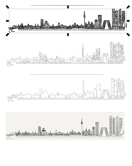
I started my search again, and finally found a new image I liked. Luckily enough, this image was an svg which makes editing much easier. I wanted to remove the frame, the letters, and reduce the detail.
Process to prepare the image
- Import the image
- Select the
pathstool on the vertical menu on the left and select all the elements to check the paths. (I was not able to select because the objects were grouped. Soobjects > ungroupfirst)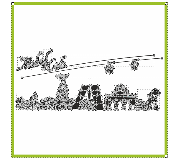 All the paths defined in the image
 - Remove some big objects (like the letters)
 Result after removing some objects
 - Focus on small objects, to remove details.
- Select all the nodes from a path to remove it.
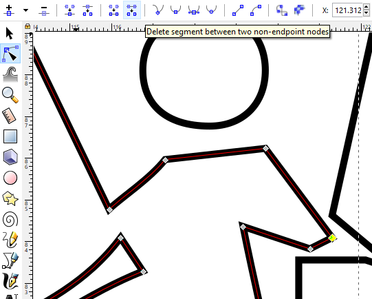
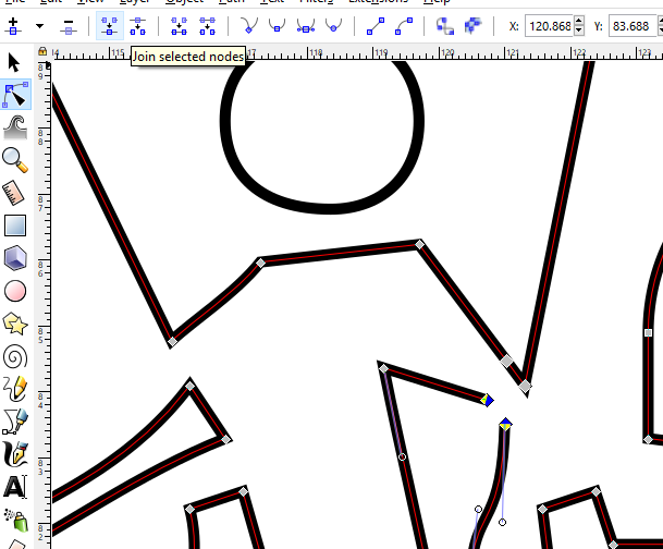
- Join paths: remove existing segments and create new ones Repeat this process with all necessary parts
- Save the final version, Selecting Fill as none
Final version of the file
Using the Vinyl cutter
The Vinyl cutter at Fab Lab Oulu is a Roland GS24. There are two options to send images to this printer: from the computer designated, use inkscape or use . I was told that using inkscape has some degree of uncertainty when trying to position the drawing. But I still tried with inkscape.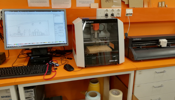
- Open the inkscape svg file
- Open the lever on the left hand side of the machine
- Put the vinyl roll in the designated place behind the machine and put the edge in its place
- Close the lever
- Switch on the vinyl cutter.
- Choose between roll (the machine assumes you are using a big enough roll), edge (the machine will look for the edge to start) or piece. I chose Edge
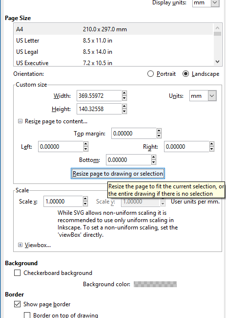
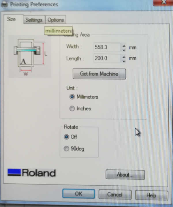
- Check the drawing is positioned on the bottom left hand corner of the document. What I actually did, was resize the document to the size of the drawing: From the
Document Settingsmenu, clickresize the document to the image size. Then, in the printer settings dialog, (shown in the image on the right), set the correct length for your case. For the width you need to keep the one given by the machine (Get from machine)
The result
The output from the vinyl cutter needed some work before it was ready.- Remove any small pieces with the tweezers
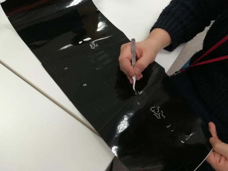 Remove small parts
 - Remove the vinyl in the background carefully, so no small part is also removed.
 Remove all the excess
 - Use transfer sheet to be able to place all the small pieces together without getting crazy
- Remove the back paper, checking all the parts remain in the transfer sheet
 Remove carefully the paper on the back
 - Stick wherever you want
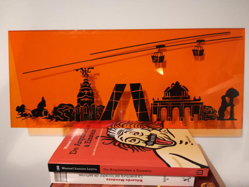 Result of the process
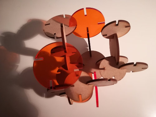
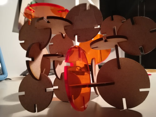
The press-fit construction kit
When looking the design closer, you can see there are at least four different sizes for the discs and a lot of different combinations for the slots.
I decided I will try
- At least 2 different sizes
- At least 4 slots per disc, with different slot positions per group combination
- At least 2 different materials
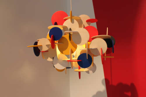
- Create one disc with the slots, with all the dimensions defined parametrically
- Copy the disc varying the parameters of the slots
- Cut, varying the size dimensions, and with the corresponding thickness and kerf
- Create one disc with one slots, with all the dimensions defined parametrically
- Copy the disc
- Create patterns to repeat the slot in different ways
- Cut, varying the size dimensions, and with the corresponding thickness and kerf
Design Process
- Create the disc and define parameters
- First, sketch a circle,
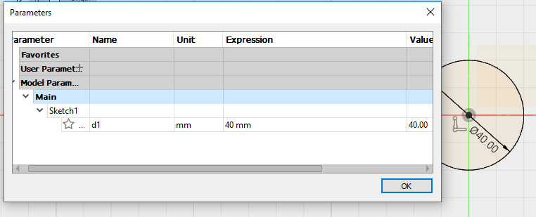
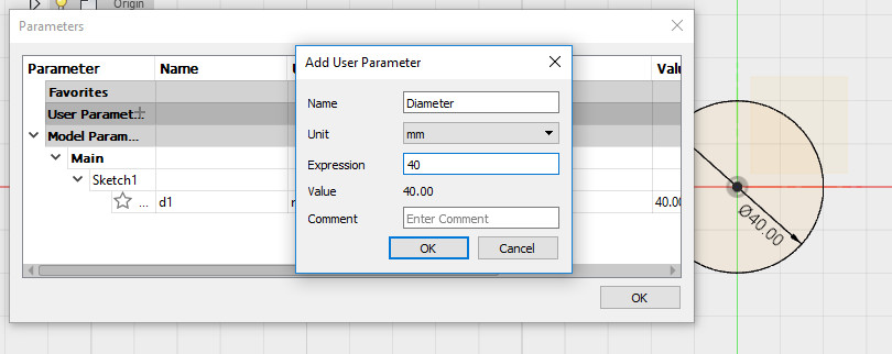
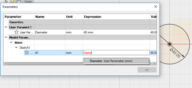
Create > New Component, then, select one of the planes (Front in my case) and thenSketch > Circleand center a circle in the origo, with a diameter of 40mm - Second, define the first parameters for the design. For this, get the parameters box from
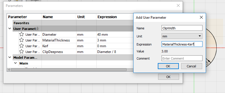
modify > change parametersand fill the values I defined the following parameters:Diameter = VALUE(Diameter of the discs)Material Thickness = VALUE(Thickness of the material to be cut)Kerf = VALUE(Estimated kerf or amount of material overcutted)Slot Deepness = f(Diameter)(how deep the slot go to the center of the disc)Slot Width = Material Thickness - Kerf(How wide is the slot)Slot Translation = f(Diameter)(Define a translation of the slot positioning)Separation = Diameter + Slot Deepness(Separation between discs)
- Create the slot
Sketch > Rectangle > 2-Point rectangleto draw a rectangle over the disc. Use the 2 points to define the rectangle as symmetrical as possible respect one axisSketch Palette > TangentTo set the lower side of the rectangle tangent to the pont in the circumference that intersects with the axis- Define the dimensions of the rectangle to the parameters
Slot DeepnessandSlot Width - To completely align the slot with the circle axis: create a construction line (
Sketch > lineandSketch Palette > Construction) between the middle point of one of the segments of the rectangle and the central point of the circle. Set it to be vertical (Sketch Palette > Horizontal/Vertical) Create > Extrude, select rectangle and set distance to Material Thickness- Replicate the slot
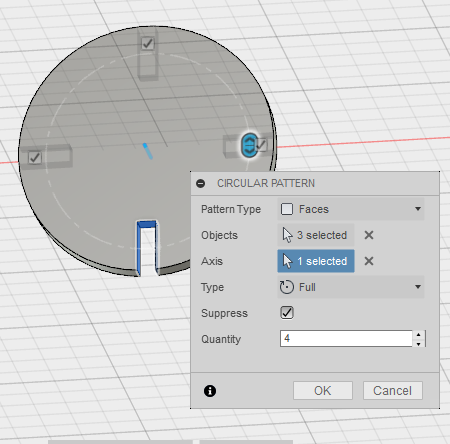
- what to repeat? The slot. This means PatternType to Faces and in Objects select the three inner sides of the slot
- how to repeat? Around the main axis of the To define an axis that goes through the cylinder
Construct > Axis through cylinder). Now you can select that axis - where to repeat? Every 90 degrees. THis means that, selecting how many slots in which arc (I select full and 4)
- Copy the disc
- Create a component (main component), for the basic shape, common to all the shapes you want to replicate. In my case, the disc with just one slot and all the parameters needed
- Create as many components as you may need.
- Copy the body of the main component to the other components. Define where to put them. From now on, you have a a set of components that:
- you can modify independently, working in each component AFTER the point in the time line they were created.
- you can modify together, working in the main component BEFORE the point where they were created.
- They all share the same parameters.
- The time line after creating 6 disks in on the bottom
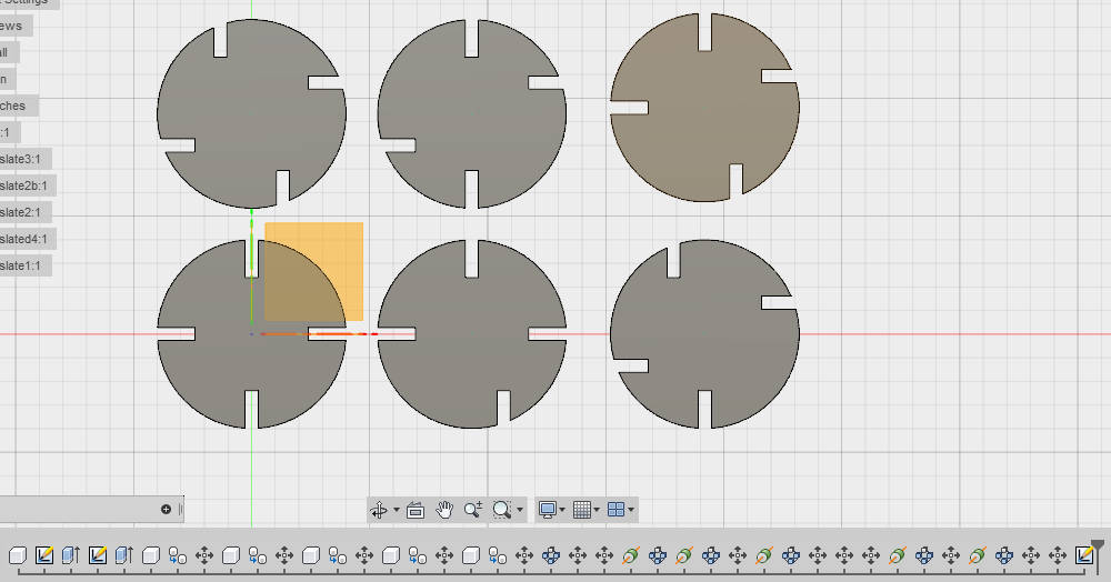 6 disks already created as defined before
 - You need to move cursor of the time line to the place of your interest, in this case, just before I created the other components
 Move the cursor in the time line
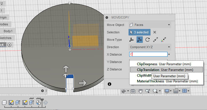
 - Then, Create a new component and copy the body of the main component and paste it in the new one. Now you are prompted to define where to put this copy. NOTE: I did this parametrically, but it turns out Fusion 360 is not ready yet for that, and it just saves the actual value. So when I increased the size, I had to reposition all of the components
 Define position of the new body
 - From now on, there is a new disk in your set of independent components. Note the new component in the time line.
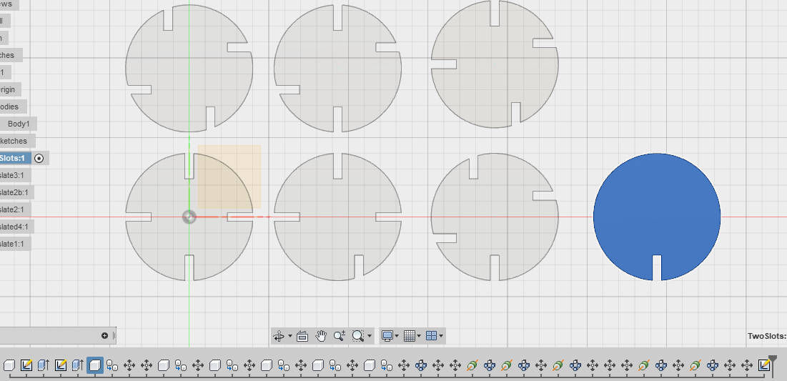 New component added
Sketch> Circular Pattern open a menu to define:
I started copying the component. I tried to do that in several different ways, but the result is always the same: as of today, if you copy a component you always copy-link. That means that whatever change you do to any of the copies or original, it will also affect all the other copies or original. And that is not what I wanted, as I wanted the slots to be differently arranged in each disc.
How to create components with a similar base, but unlinked.
Cutting Process
- Prepare the file
Model > Drawing > From designOpen a projection of your design. Select the components or the model- You can select the projection and place it in the drawing with the desired scale (1:1 in my case)
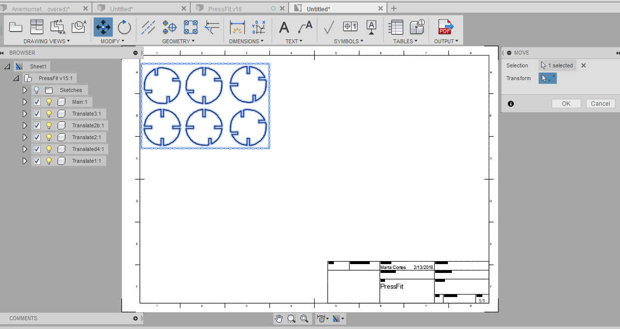 Projection View for the 3D model
 - Remove all the borders and forms in the document
- Export as PDF
- Open pdf with inkscape
- Select all and and set the Fill and stroke values for cutting: No fill, stroke 0,02
- I wanted to double the figures, so I copy&paste the block. Then saved.
- Open with Reader and send to laser cutter. Then, in the
properties > advanced, choose the settings. The settings are mainly- Speed: How fast the laser moves through the material. (Slower means deeper cuts, but too slow might burn the material)
- Power: The power of the laser beam. (More power means deeper cuts, but too much power might burn the material)
- Frequency: The frequency of the laser pulses.
- Finally, send to the laser cutter
- Prepare the machine
- Check that the ventilation and the air pressure are on.
- Calibrate the Focus. This process positions the material at a given distance from the laser head. The distance is determined by a metallic triangle you hang from the laser head. Select
focusin the menu and move the tray up and down until the material touches the triangle, without pushing it up. Then press the joystick.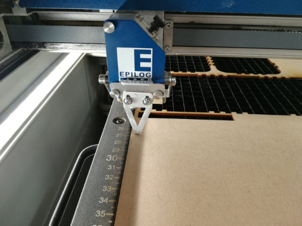 Triangle to determine focus
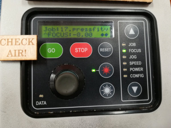 Set focus with the joystick
 - Set the Origo. This determines where the machine will start to cut. Always remember it will be the top left corner of your drawing. Select
Jogin the menu and ove the head with the joystick; press the joystick when ready - Select
Jobin the menu, select the file from the list and pressGo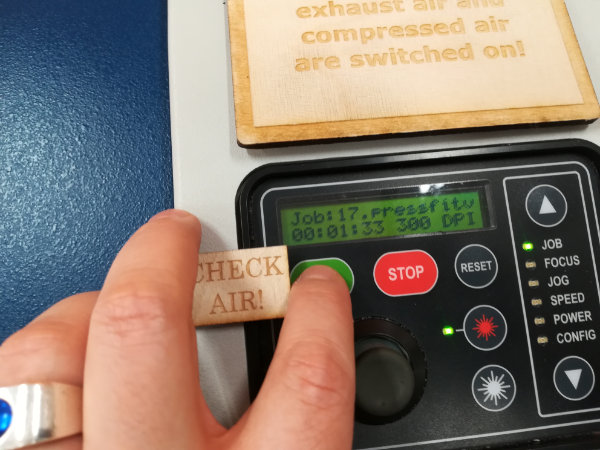 Choose file from the Job list and press go
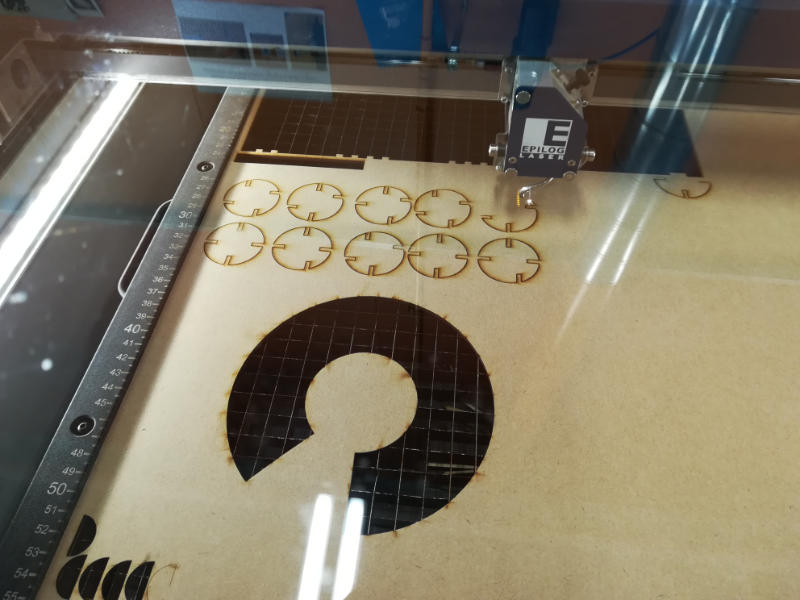 Cutting
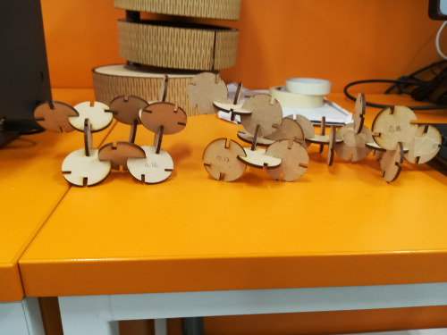
 - The result
- 2 different sizes: Diameter 40mm and Diameter 60mm
- 2 different materials: MDF and Acrylic.
- 3 different kerfs for one model: This was because the first Kerf I chose (0.17) was not smooth enough, although it fitted. I did not thought it OK, so I cut changing the kerf to 0.18. These obviously fitted even worse. So finally I cut with kerf 0.16
PDF file from FUSION
Prepare the PDF file in inkscape
Conclusions
- Follow the steps to prepare the machine! I missed some joystick pressing, so the origo was not set, so the head started in an unexpected place.(STOP-> RESET-> and start again)
- Need to do some small tests with the material before you start, in order to get the correct kerf
- I found not that big differences between the options with 0.16, 0.17 and 0.18. Does the kerf also depends on the focus setting?
Group work: Characterize the laser cutter
Link to group assignment page
Note: There was some confusion on how to document the group assigment. The group documentation can be found in the group page, in the link above. The text below is my version of it I did just in case, before we got the decision.
As we are 8 people doing the Fab Academy in Oulu, we were instructed to split in 2 groups so we could work more comfortably around the machines.
In my group we were Ari Vuokila, Kati Pitkänen, Megumi Iwata and me.
Process> Planning, cutting and measuring
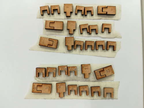
We first decided a time that was suitable for all. And after the introduction from the local instructor, we started to plan how would we proceed. We asked Eino how did he do it last year, and we used that as an starting point. We thought together how to proceed: we would draw some pieces that we will afterwards cut with different parameters and in at least two different materials. The plan was to engrave in each piece the settings we would use to cut each piece.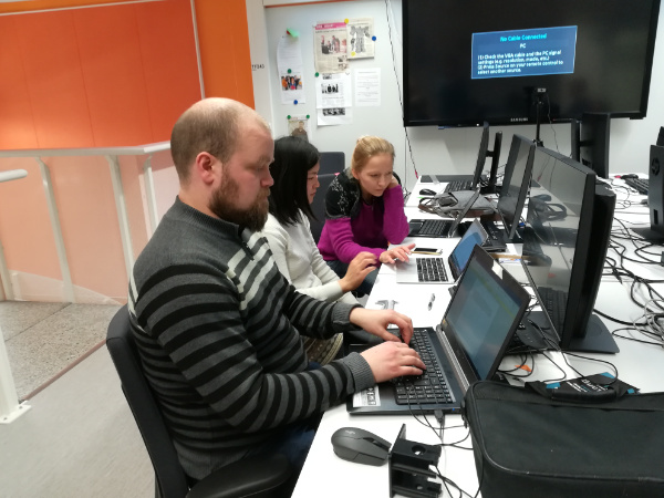
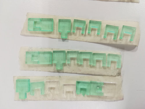
Megumi started to draw the designs while we together discussed the different sizes we would need in order to better determine the Kerf of the lasser cutter, Ari started to write a document to describe what we did and I started an excel document to write and later share with all. We all the pieces to be 10mm wide, habing the male pieces a tooth of 5mm or 5.1 mm, and the female pieces slots of width 4.7mm, 4.8mm, 4.9mm, 5mm and 5.1mm. Soon, Kati started to prepare the laser cutter to start cutting. We would start with Acrylic 3mm, and the default values for speed, power and frequency. We would then vary the speed. And later, do the same with MDF 3mm.
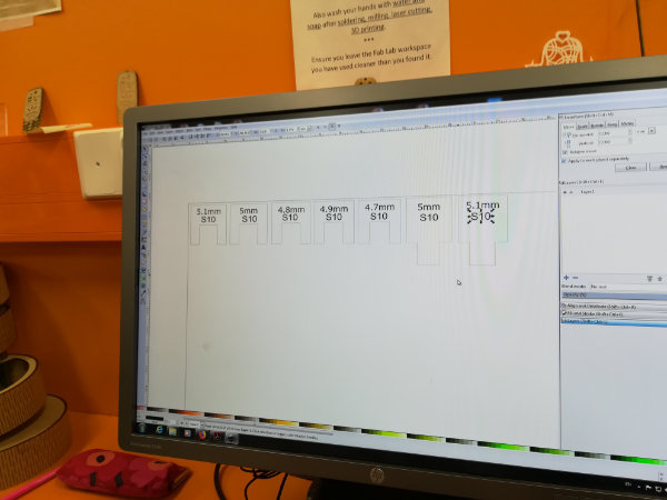
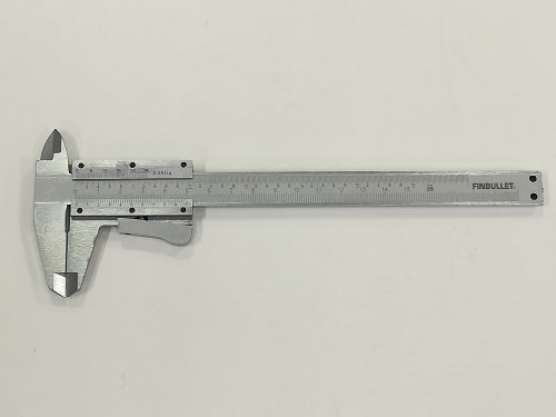
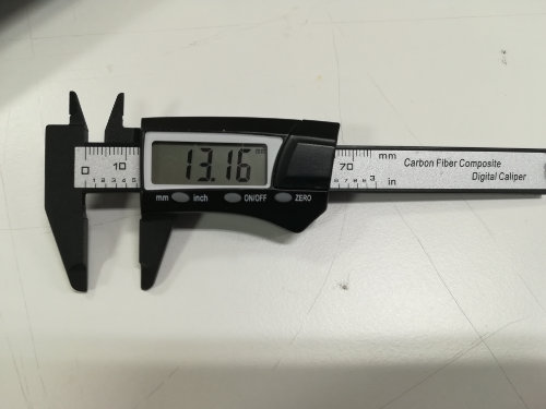
Out initial plan was to measure the slot of each female piece (5) plus the tooth of the male pieces (2) for each of the 10 different settings we planned. But when we started to use the calipers we realized it was going to take long time. What we ended up doing is measuring the outer part of two different pieces.
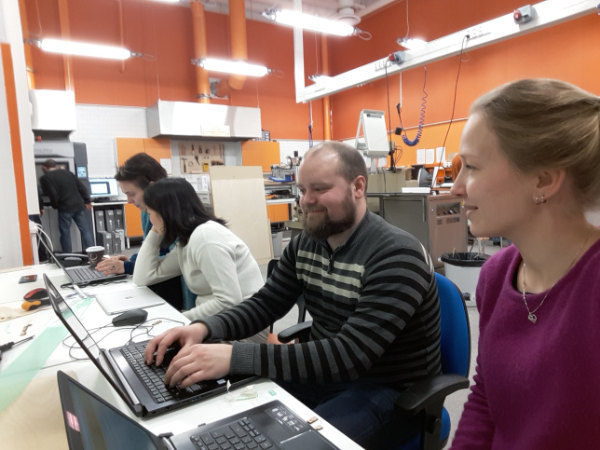
We measured both with the analog and digital caliper. Megumi and Kati meassured while I was writing the data and Ari was describing the process. When I later organized the data, we decided to just keep the data from the digital caliper, as the other data differed a lot from average values we could find in the internet or from last years projects.
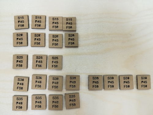
The pieces we cut:
Data summary: Calculations
I created some summary tables with the data. The outer pieces should be 10mm. So calculatingKerf = 10mm-ValueMeasured
| S6 | S8 | S10 | S12 | S13 | S15 | ||
|---|---|---|---|---|---|---|---|
| Acrylic 3mm (P100,F100) | |||||||
| piece 1 | 0.2 | 0.17 | 0.09 | NO CUT | - | NO CUT | |
| piece 2 | 0.22 | 0.13 | 0.12 | NO CUT | - | NO CUT | |
| MDF 3mm (P80,F20) | |||||||
| piece 1 | - | - | 0.18 | - | 0.16 | - | |
| piece 2 | - | - | 0.16 | - | 0.14 | - | |
| MDF 3mm (P100,F100) | |||||||
| piece 1 | 0.2 | 0.2 | 0.14 | - | - | - | |
| piece 2 | 0.15 | 0.15 | 0.15 | - | - | - | |
What we did with the female/male pieces was to test how well one fitted to another. We matched the best case for each combination of material+settings and we got the following values, represented as male[mm]/female[mm]:
| S6 | S8 | S10 | S12 | S13 | S15 | ||
|---|---|---|---|---|---|---|---|
| Acrylic 3mm (P100,F100) | |||||||
| piece 1 | 5/4.7 | 5/4.7 5/4.8 | 5/4.7 | NO CUT | - | NO CUT | |
| MDF 3mm (P80,F20) | |||||||
| piece 1 | - | - | 5.1/4.8 | - | 5/4.8 | - | |
| MDF 3mm (P100,F100) | |||||||
| piece 1 | 5/4.7 | 5/4.7 | 5/4.7 5.1/4.8 | - | - | - | |
Kerf = (Male[mm]-Female[mm])/2As she was planning to use cardboard in her pressfit project, Megumi decided next day to cut some cardboard squares with different values and meassure them. Those values can be found on the group assignment page.
Conclusions
- Clearly, the kerf depends on the material
- The kerf depends on the speed (decreases with the speed)
- The values are clearly orientative. Test always first!!
- If I desig for Kerf X but
- the actual kerf is HIGHER: the female slot is wider/ the male tooth is narrower
- the actual kerf is LOWER: the female slot is narrower/ the nmale tooth is wider
Resources
- inkscape: vector graphics editor
- Fusion 360
Once done
Summary
- I have learnt how to use the vinyl cutter, by doing my own project
- I have learnt what is the kerf and how to calculate it, with my classmates
- I have learnt to do a parametric design of a 3D model using fusion 360
- I have designed and cut a pressfit kit
- I have documented it all
Difficulties
- Understanding the timeline of fusion 360 took a while, and how to copy with no link
- Still pending: check how to move components parametrically.
Learnings
- There are always going to be last minute testings and adjustments with the laser cutter
- I need to learn to position better the origo to make a better use of the material
Tips
- Always follow the task list when preparing the laser cutter
- Do not forget to set the origo in the laser cutter!


