
My plan is to draw an initial design for different parts of the Final Project. First, I add a new paper sketch for the project. With 2D, I plan to make an sketch of a possible design for the interface of the final project. This interface could be a board where different clothes light up depending on the temperature. With 3D, I plan to do a first design of the anemometer. If I would need to adjust any image, I would use GIMP. Our local instructor for this week, Yrjö Louhisalmi, made a first introduction to Fusion, and highly recommended it.
To Do
- Model a possible part of the (possible) final project in 2D and 3D
- Explain the process
- Include the original design files
The "Doing"
Paper sketch the first ideas
When I started to define the Final Project idea I did a first paper sketch to better explain it. But to start the actual design, I needed to sit again and sketch better the different parts I may need.
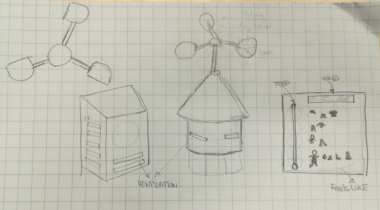
- I need a place to put the different sensors (temperature, anemometer, humidity??)
- I need the structure to build the anemometer
- I need a board for the actual interface to show the information
Using gimp to join two images
I already had Gimp installed in my computer. Sometimes I use it for picture transformation or resizing or small editions.
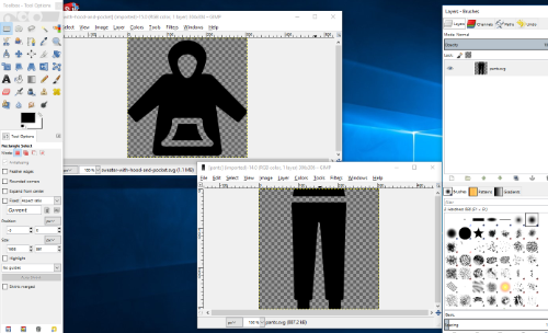
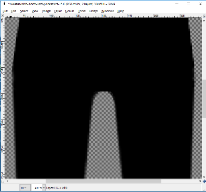
For creating the board for the thermometer, I needed some images of clothes. I did find some, but there where others I could not find easely. So I decided to create some of the clothes I needed from the images I already had. This was the case of the overall: I used some pants and a sweater with a hood for that. I opened those in gimp, as it can be seen in the following picture. The tools are on the left and the layers options are on the right.
To manage to create the overall, I had to follow the following steps:
- Enlarge the canvas of the sweater image with the length of the pants images, so both of the pictures would fit in the same canvas
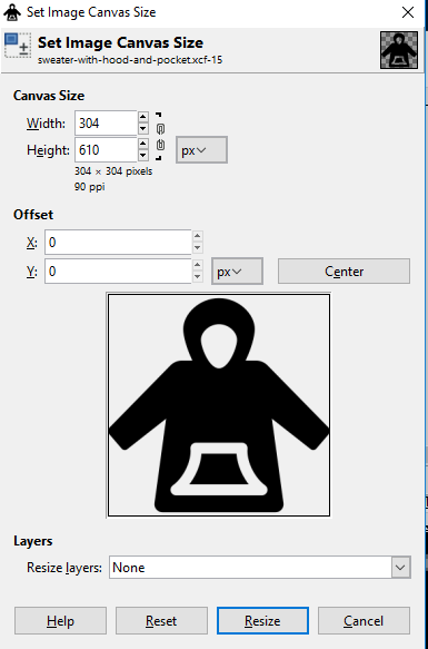 Change canvas size
 - Create a second layer in the sweater image
- Copy the pants image to that secondlayer
- I had to do the pants shorter and wider to fit for an overall so
- I selected (square selection tool) the top of the pants in that layer and deleted that part
- I selected (square selection tool) the pants in its layer and chose layer>scale layer until I was satisfied
- I selected (square selection tool) the part of the sweater that remained transparent and painted it with black (bucket tool)
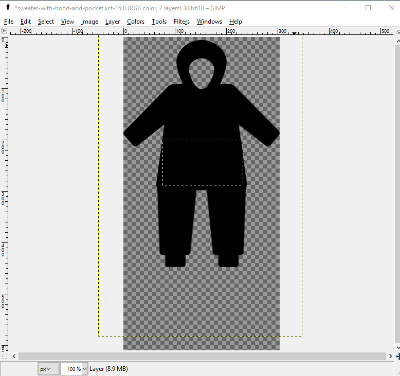 two images joined
 - I still had to do some manual work: erase (Erasor tool) on the outer sides and paint (pencil tool) in the middle of the legs.
 Some manual fixing
Using inkscape for the thermometer interface design
I downloaded inkscape from the project page. I did not have any problems for that. I decided to go withouit any tutorials for inkscape, and see how far could I go. I have to say, though, that I got some tips from one of the local instructors; and that I had been previously in a couple of workshops where this program was used.
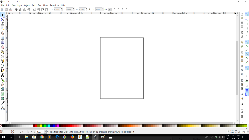
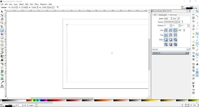
When the program is first open you see an empty page and lots of tools menus everywhere:
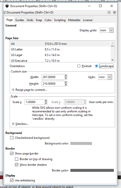
My plan is to draw a possible design for the thermometer with clothes scale (possible final project idea). In this possible design, the base is a board. So I start drawing the board. First, as in my vision the board is horizontal, I rather work with the inkscape in landscape. So I found where at File > Document properties.
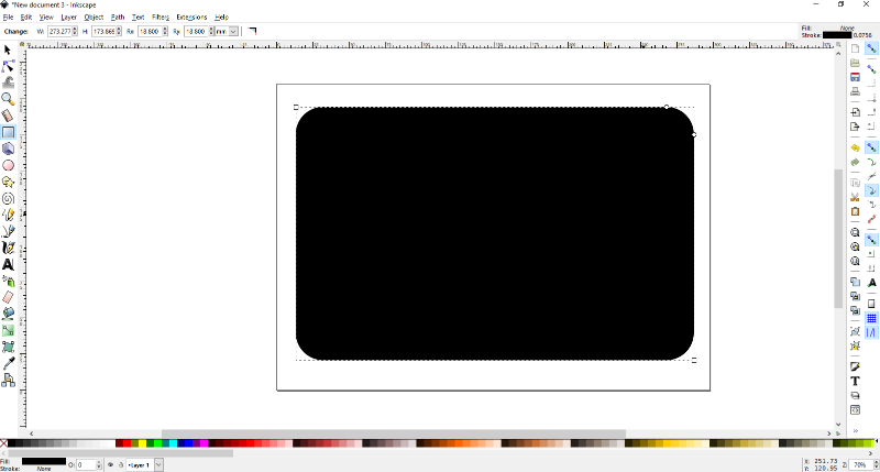
Then, by clicking on the left menu the Create rectangles and squares, I managed to draw a big rectangle, that by default came with the rounded corners. Good, because that was my option. I discovered, though, it was possible to put the corners square again quite easily: on the top, there is information about your object, like X, Y positions and width and height. There is also information on the Radius for the corners, along with a button, that reshapes the corners back to square if pressed.
Then, I would have to remove the filling and just left the stroke. To do that, the menu is in Object > Fill and Stroke. Then a submenu box is displayed on the right hand corner for you to update your choices. In my case:
- fill: No paint
- Stroke paint: Flat color, black (#000000ff)
- Stroke style: Width: 0,02
Now it is time to fill the square. First, I do some seaching for any useful images of clothes. Once I have them, I need to follow the steps to incorporate the pictures to the inkscape drawing.
File > import: import the picture to the drawing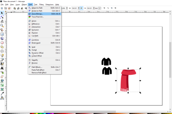 import a picture
Path>Trace bitmap: with the picture selected choose this option from the Path menu. Notice that the threshold may vary with the pictures (depending on the colors and shades)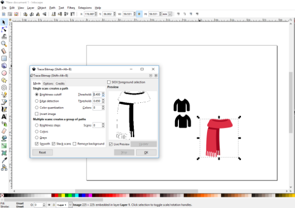 Choosing threshold
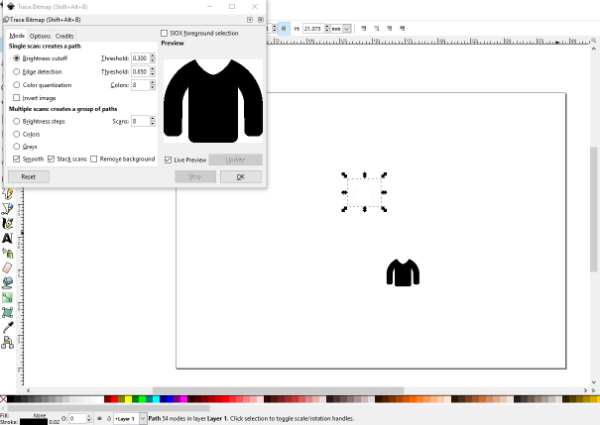 Choosing other threshold
- Once done, move the new object to see the image (and delete the image if you are done). You can define the
Object>Fill&Stroke propertiesnow.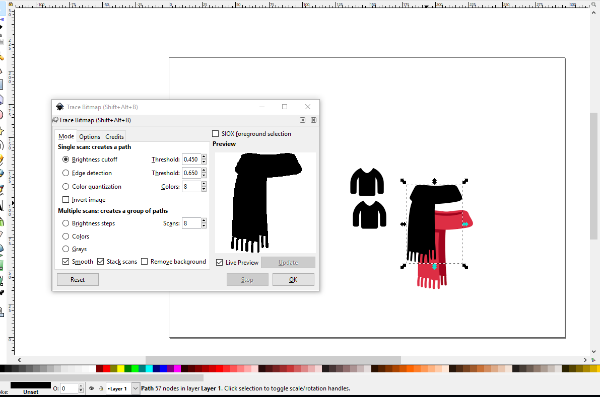 Once done, find the image to delete it
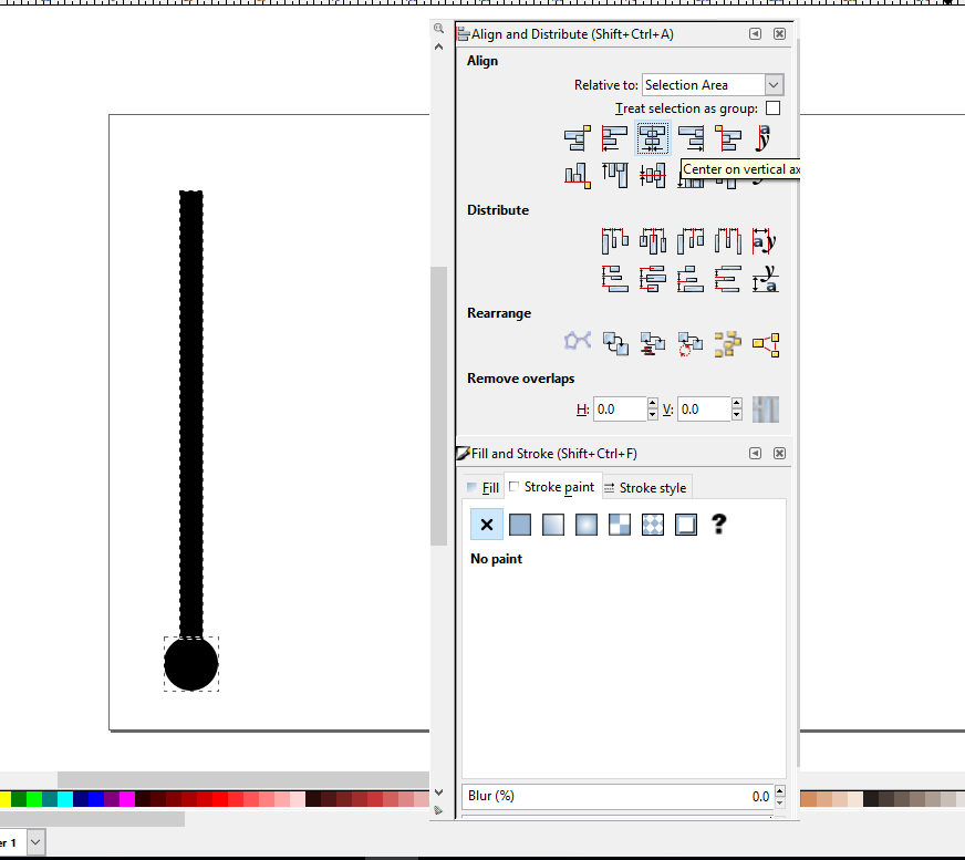
The thermometer is a very simple figure, thus I decided to do it by myself. The main steps would be:
- The thermometer is composed by a circle and a long vertical rectangle
- The figures need to be aligned
- and maybe the rectangule must be soften on the top
create circles... and drop one and then select create rectangles and squares and drop the desired rectangle. Then, to align them, you select both and from the Align and Distribute menu, you choose Center on vertical axis.
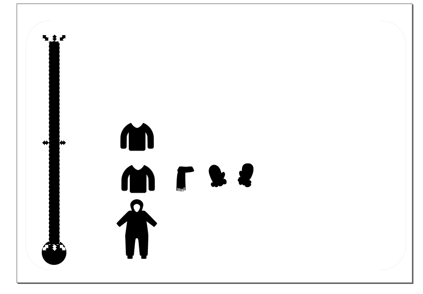
Finally, you can soften the borders of the rectangle on the top by means of varying the Rx and the Ry values for the square. You can access those values by clicking on the object. The different values of the parameters wil be shown at the top left hand.
The final result could look as in the following image, but adding more clothes
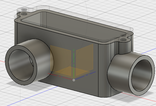
Using Fusion - Tutorial
I decided to start with this tutorial in youtube for fusion. In this tutorial they guide you to design the piece in the following picture
With this tutorial I have learnt to
- Sketch on the Plane to Start drawing figures
- To create a 3Dmodel with Extrude from those figures
- Sketch and Extrude on different sides of the 3D model
- Usage of construction lines
- Extrude to an object by an offset (Extrude parametrically with that object)
- Extrude in and out to create figures that create holes in the 3D model
- Correcting gaps that can occur when extruding
- Mirroing a feature
- Editing features from the history
- Modify the history line to reorder commands for a more efficient creation
- Modeling a second object linked to the other one
- Use Projection to define sketch
- Create sketch over a face of other model
Using Fusion - Lets Do it
After doing the tutorial, I felt confident enough to start the design of one of the parts of the system: the anemometer
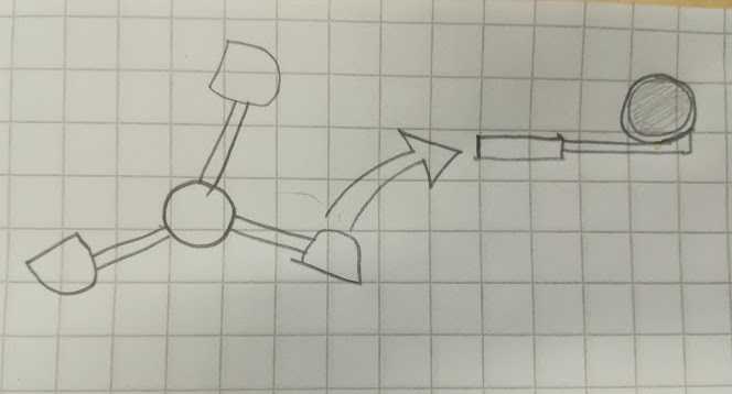
These are the steps I (Should have) planned
- Sketch the central circle and extrude
- From the arc of the circle, sketch one hand of the anemometer as a rectangle and extrude
- Note! Sketch is only possible in flat surfaces! Options: use auxiliar plane or do as another component
- Replicate the arm, rotating 120 degrees
- Note! I ended up creating the cup first (next step) and then replicating the whole arm+cup
- Do the cup as an emptied semisphere
- Replicate the cup in each arm
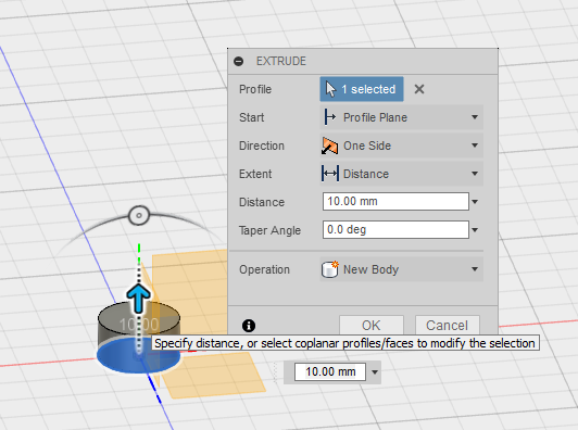
I create a New Design by clicking on the plus simbol on the top. I first check that I have the correct units (mm) and switch on the origo. I create a new component at name_of_the_design > New Component to work with the central piece. From the system of reference on the right hand corner, I choose the TOP, and so the view is turned to that plane. By right-clicking on the plane a get a menu and Create Sketch > Options > Center Circle to draw a circle in the Origo. I choose a diameter of 20mm.

I extrude the circle by pressing Qand selecting the circle surface. There are several options for extruding (one side, the other, bothsides...)
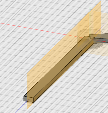
My initial plan was to select the surface around the around piece, sketch a rectangle and Extrude it. WRONG! I spent a long time, until I figured out it must be a plane surface to be able to sketch on.
I decided then to create a component to make one of the arms of the anemomenter and later on, try to fuse it to the center piece. After creating the new component, I switch off the central component. I then follow the same steps as above to create the arm, with the difference that I start from a rectangle.

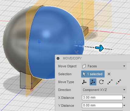
move > copy and select what kind of movement (translation, rotation...) and other parameters (eg the rotation axis and the rotation angle for rotating) and click Create Copy

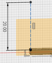
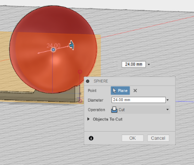
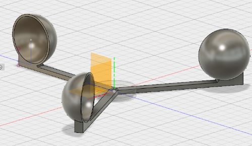
I spent some time trying to figure out a way to create the sphere over the arm. I managed by creating a construction plane, that is, an auxiliar plane that is not part of the design. Construct > Offset Plane, select the face where I want to put the plane, and set an offset of 0mm. I also create a construction line to set the center of the sphere. For that, I press L, draw the line and then set it as construction line by selecting the line and then click Construction on the right hand menu.
modify > draft to create a slope for better fitting

Create > Sphere (with the dimensions of the cup), and use it as an editor tool, to cut the structure Operation > Cut.
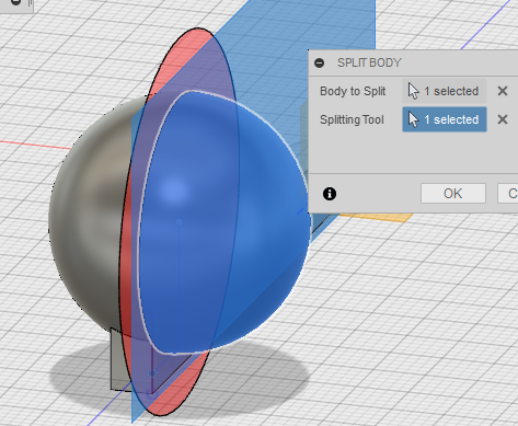
Now I create the cup. For that, I draw a sphere the same way than before but choosing Operation > Create body. Then I have to cut sphere in half. For this, I had to do some research. And I found that people usually creates semispheres by revolving arcs. In any case, I decide to stick to my plan. To split a body, it is necessary to indicate the cutting plane. So I set a construction plane in the middle of the sphere where I want to cut Construct > Offset Plane. To cut the sphere, I select it and Modify > Split body and then set Cutting tool > Select to the construction plane. Then, to remove the other half, I had to play a bit around. What I filally did was rightclick the half to remove, move it from the design, rightclick in the list of bodies for menu and then Remove
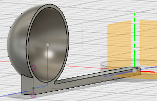
Finally, I just need to replicate the arm with the same steps than before
When trying to export the files for 3D printing, I noticed I made a bad decision when defining the elemenst of the design. I have two components that, to my understanding now, cannot be sent together for 3D printing [UPDATE(week4): YEs you can, just activate the whole model, not component by component].. What I needed was different bodies of the same component. Luckily for me, I discovered you can get the body from one component and past it to the other. You do not paste the different sketches, but the final product.
In any case, to get the fusion file of your design File > Export and to get the file for 3D printing Make > 3D Printing and select the component/group of bodies you want to print
Resources
- Gimp
- inkscape: vector graphics editor
- Fusion
Once done
Summary
- I have learnt to draw a design in 2D using inkscape
- and in 3D using Fusion 360
- I have documented both processes in my personal site
- I have updated the final project page accordingly
Difficulties
- Learning fusion terminology and what each thing implies
- Fusion is a powerful tool, but painful nevertheless. I have noticed that if I have to draw and eliminate several times the same thing before having a final version (eg a construction line in a plane) I end up having to delete the whole step and start from fresh.
Learnings
- Reducing png figures takes loong time
- Needed to understand differences between components and bodies. When I was trying to create the files for 3D printing, I understood you cannot send 2 componets at the same time.
Tips
- Try to sketch the steps to do a design before starting the design
- One component or groups of bodies is what you can 3D print. You cannot 3D print a group of components! (If you need, move the Body/is of the desired component into the other component). Wrong, check UPDATE