
Our instructor this week was Antti Mäntyniemi.
To Do
- Design a small 3D object and print it.
- Scan objects (that could be printed).
- Learn the characteristics of different 3d printers
The "Doing"
Design and print a 3D object
The design
For this week, there are certain rules for the design of the object. It must be so that it could not be made substractively.
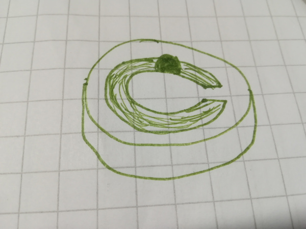
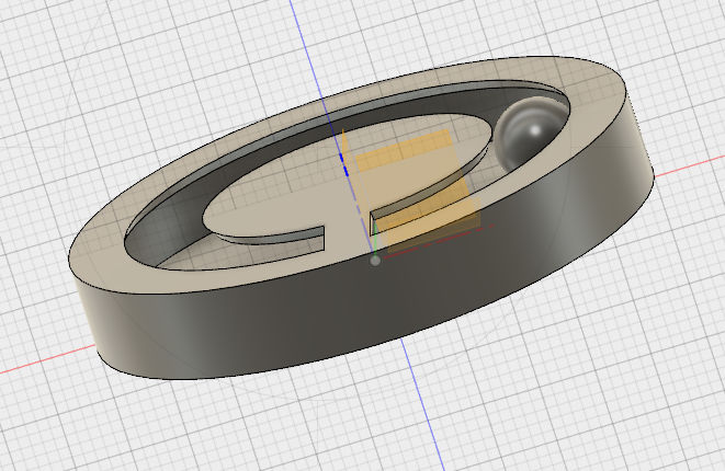
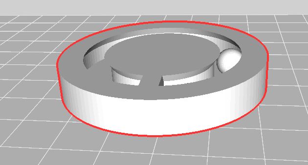
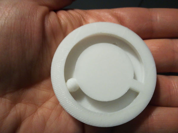
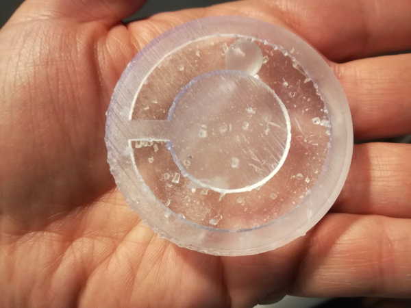
My design consists in a round box with a ball inside that should follow a path. The ball should not fall from the box; which means its diameter is bigger than the width of the path, therefore it cannot be introduced afterwards.
This cannot be done substractively because:
- it is not possible to do the inner rail where the bit needs to drill inside side wise
- it is not possible to sculpt the ball inside the hole with a vertical bit
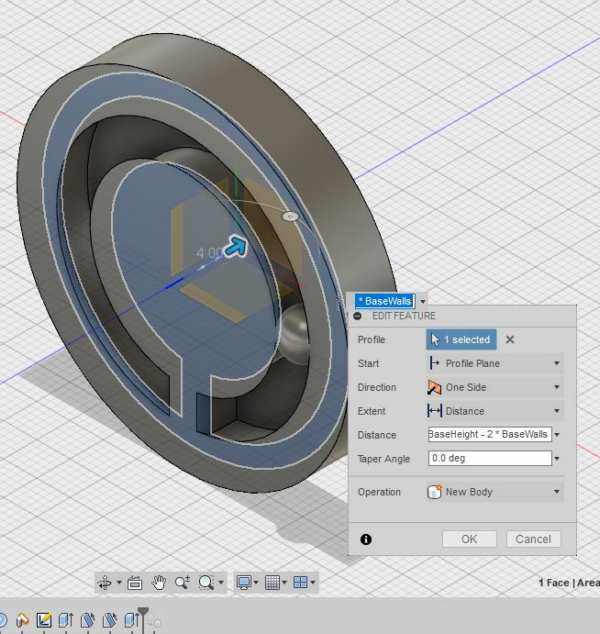
I have decided to do it with Fusion 360
- Create 2 components: one for the box, one for the ball
- The box:
- Sketch a circle
- Extrude
- Shell
- Create certain path (circular?) which width depends on the ball size
- Extrude the path to eliminate it from the top part of the box
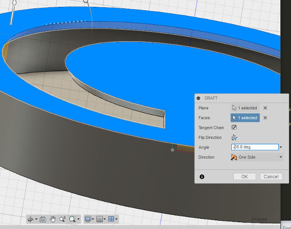
- Draft the borders to better hold the ball
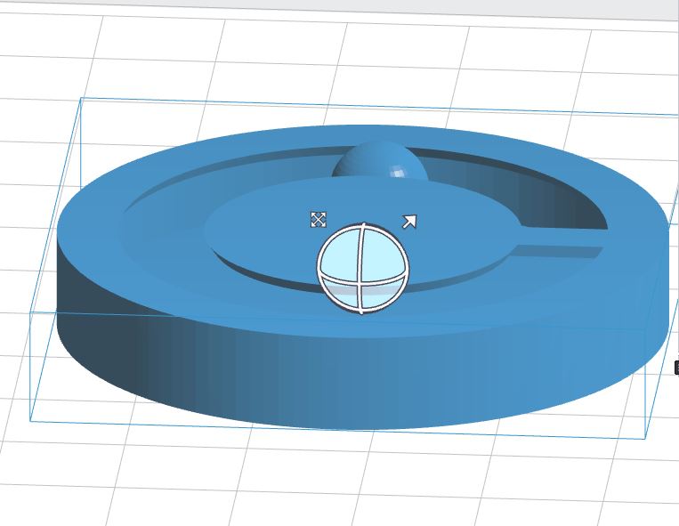
- The ball: create an sphere
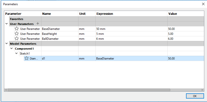
sketch > circle. Then, I defined some initial parameters
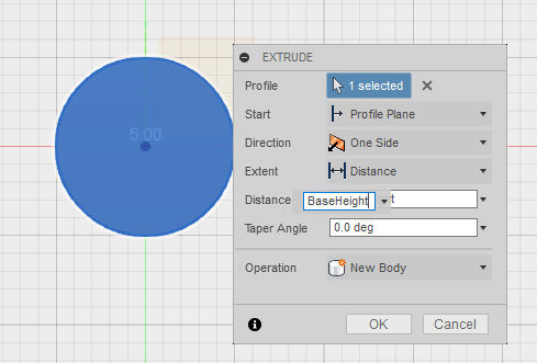
create > Extrude the sketch
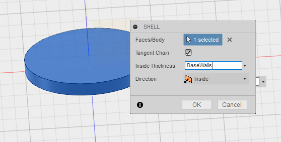
Modify > Shell
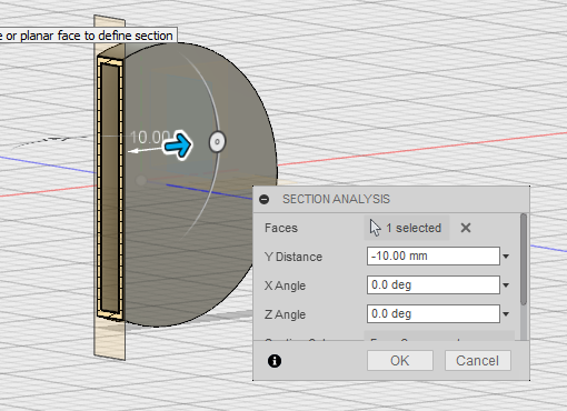
Create > sphere and put it inside the base. This way, I was able to "calculate" the width needed for the path (so the ball wont go out but still, it will be printed as a separate object).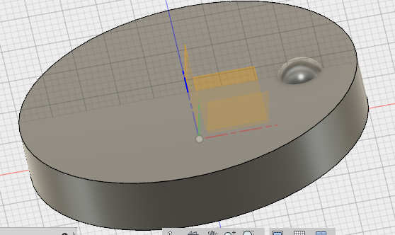
sketch > circle on the top side of the base. The Diameter of each circle depend on the ball. Also, I draw a rectangle sketch > rectangle that created a bridge between the inner part and the outer part: this way, the inner circle of the top part of the base is attached to the rest of the base.Then, I used the
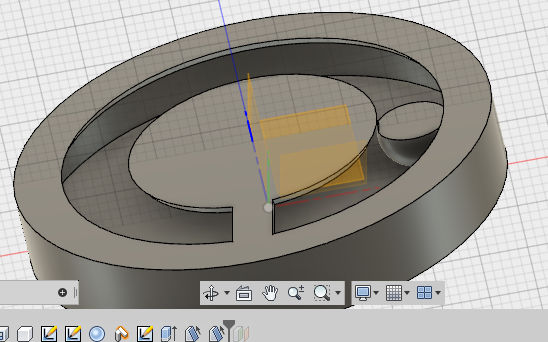
create > extrude just for the path. This caused the ball to get cut also.
Modify > Draft
CHANGES IN THE DESIGN
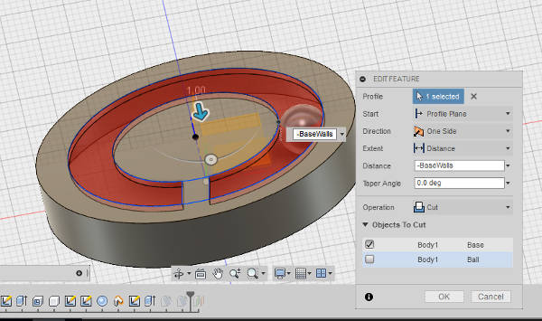
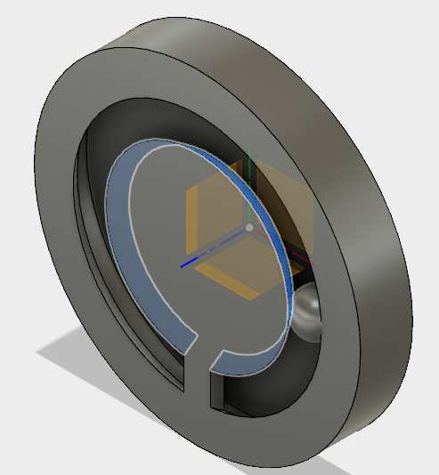
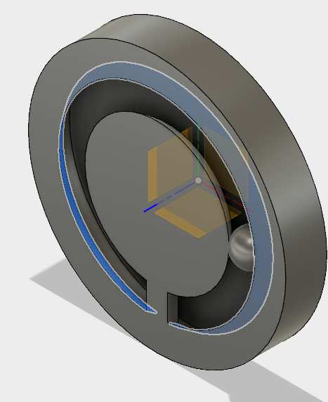
I had to modify the design a bit for sindoh printer. I decided to add myself material under the lid in the middle, to be sure it got printed correctly. For that- I create a draft in the inner circle
- I create a draft in the outer circle
- Extrude the face left in the circles
The printing
For my personal assignment I printed my model in 3 of the 3D printers that are available in our FabLab
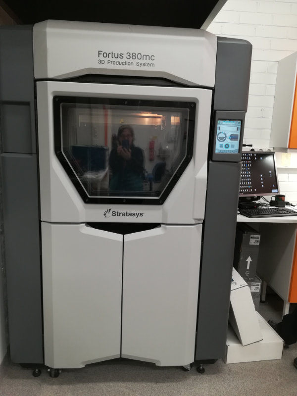
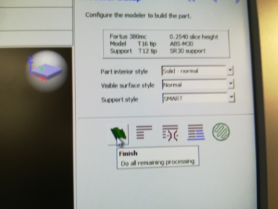
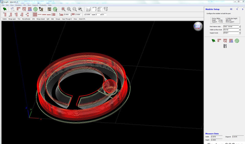
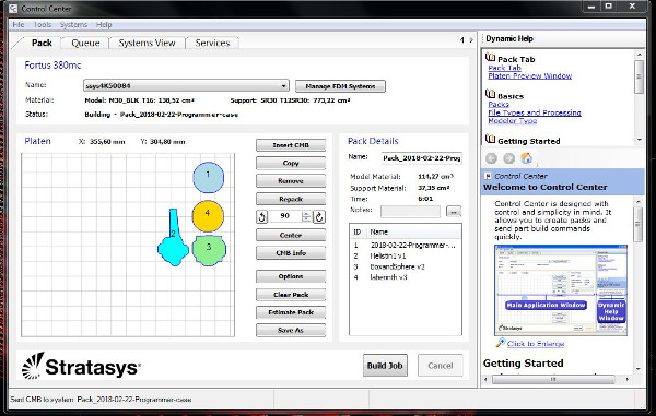
STRATASYS Fortus 380mc printer
THis printer is based in Fused Deposition Modeling (FDM) Technology. it prints from bottom to top, by layers (each layer with each corresponding model material and support material) I opened the .stl file I obtained from Fusion 360 in the dedicated computer, with the Insight application. I left the default settings, and pressed thegreen flag button.
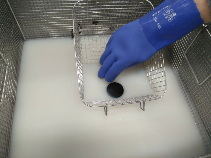
First, strip the bottom layer off your print with a spatula. The support added by Stratasys has to be removed by introducing the piece in NaOH. It is therefore necessary to use rubber gloves to put the piece in the tank and to remove it later from there. The piece should stay at least 10-12 hours in the solution. It may take longer if the design has a lot of holes and corners.
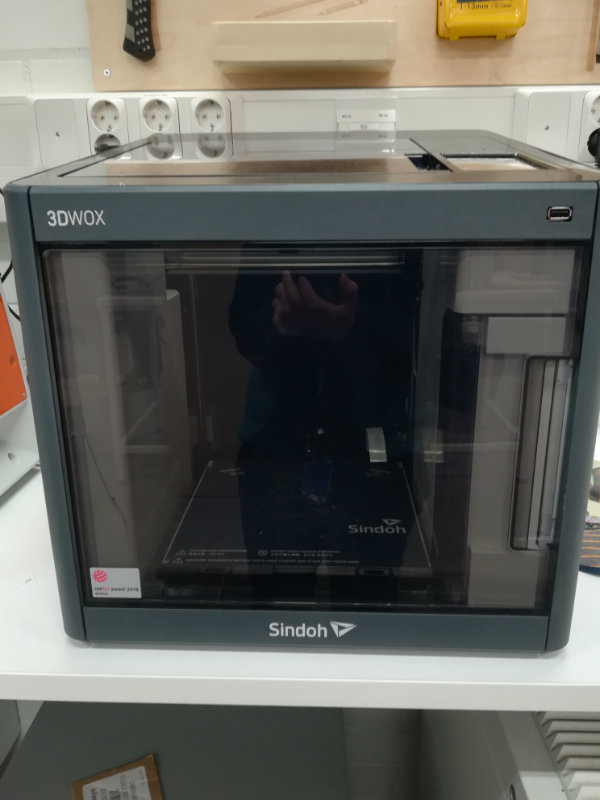
SINDOH PRINTER
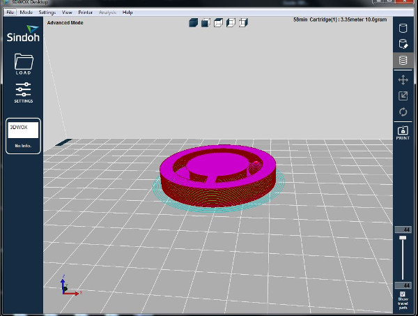
This printer uses Fused filament fabrication (FFF) technology, which is a 3D printing process that uses a continuous filament of a thermoplastic material. It does not use different materials fot the model, support nor bedding.The special characteristics of this printer forced me to rethink my model. In this printer, adding the support material implies to fill the necessary gaps with the same material with which the model is printed. This means mainly that having an empty box with the path in the lid, could end up filling the structure.
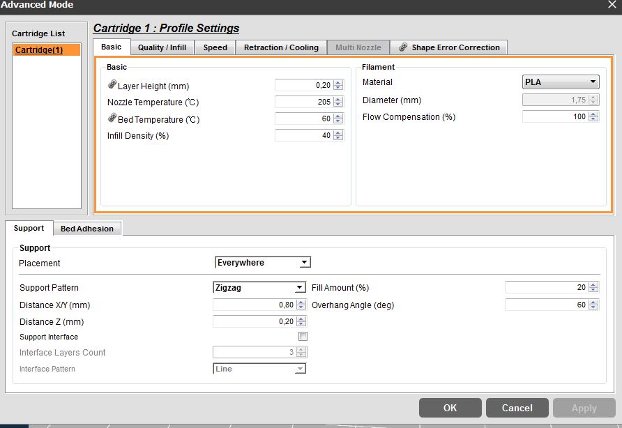
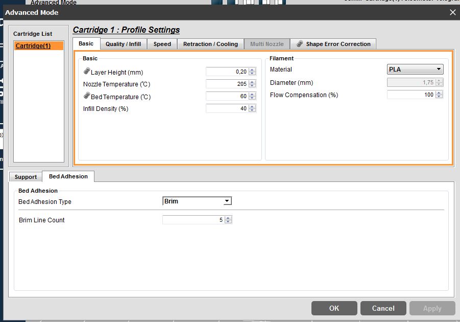
Just to be safe, I modified slightly my model to make sure it will work. I opened the .stl file I obtained from Fusion 360 in the dedicated computer, with the 3DWOX application.
I added some bedding, as we learnt to do in the group assignment , and then the support material. In this case, the only thing that got support material was the ball, and very little.

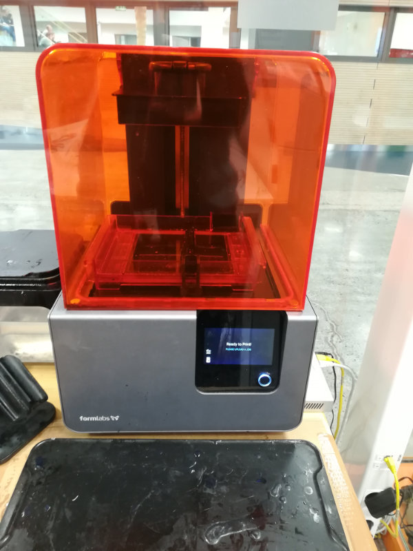
FORMLABS PRINTER
THis printer is based on Stereolithography. This means, a uv light hardens the resin by illuminating it according to the model.I opened the .stl file I obtained from Fusion 360 in the dedicated computer, with the PreForm application.
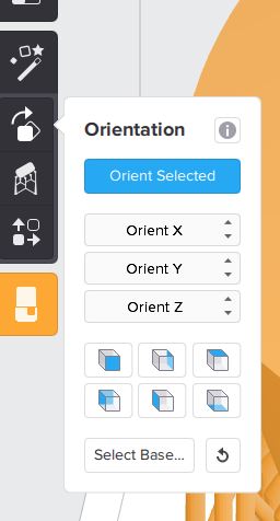
orient selected, it automatically puts the model in the correct position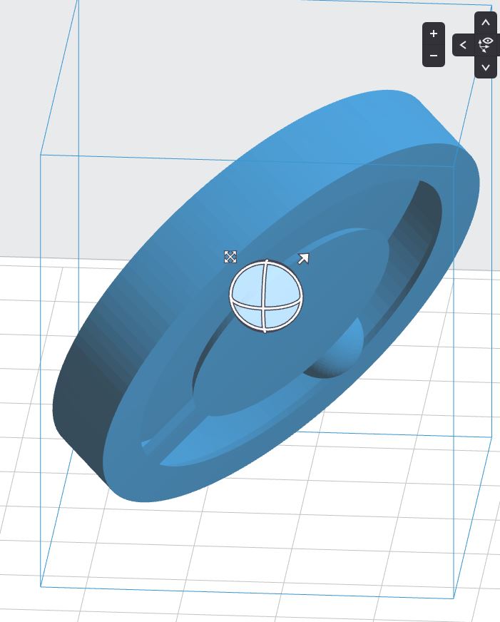
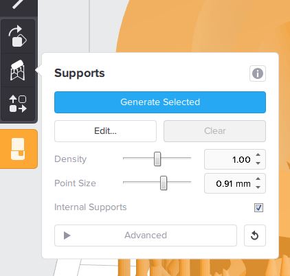
Now, by choosing supports from the menu on the left, all the supports are generated. You can then inspect those to add (if needed) or remove.
generated selected it automatically shows the support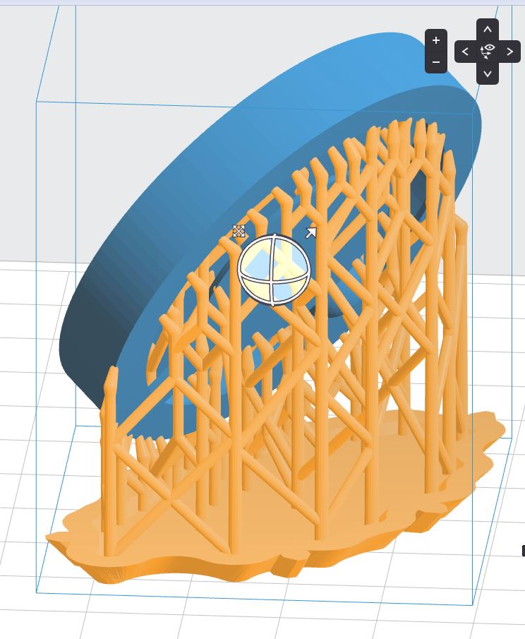
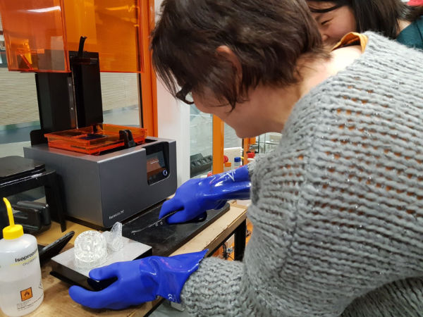
When removing the piece, it is very important you do not touch the resin at all. That is why all the process of extracting the piece is done with thick rubber gloves. Also, each tool or piece of the machine that has touched the resin, it is immediately cleaned also with isopropanol.
After removing the piece with the spatula from the base, it is submerged in two different tanks of isopropanol. The first one is usually a bit more dirty, because it gets the most of the residues. The second one has a cleaner solution. The piece stays around 10 minutes in each of the tanks. After that, you need to use some tool to mechanically remove (cut) the supports from the piece. Finally, sanding is also needed for a better finishing.
generated selected Removing the piece from the "base"
REFLECTION
- I was thinking that formlabs would produce the better piece. But there were a couple of issues:
- My walls were quite thin in the initial model: 1mm. It turned out that, for formlabs printer, it is so thin that the top tab is even flexible. So it bends too easily. Maybe it would have been better to print the
- The support material from formlabs is really difficult to remove from the inner parts, so the ball does not slide smoothly currently
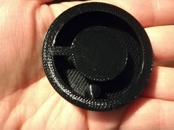
- The best result I got from stratasys. The ball really rolls smoothly on its path.
- The result from sindoh is also quite good. The ball rolls almost smoothly. There is a small imperfection on the ball due to the support, that makes it get stuck sometimes
Scan a 3D object
Photogrammetry & ReCap
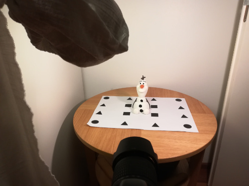
The idea is to reconstruct a 3D object by taking photos of it. So, take several pictures of the object in a certain way, pass them to an special software (in my case ReCap photo) and obtain a reconstructed mesh of the object.
There has been a lot of try&error with this task. I read some recommendations from former students and prepared my setting accordingly. THus, I put under the figure a paper with a patterns that could help the software afterwards.

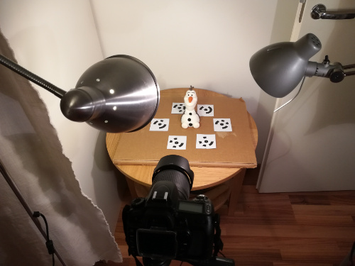
Then I changed my settings into a new location, so I could move around the object:


- Light was the same
- Same amount of pictures: 54
- Two different rounds with different angles in both cases: one round from the front and one round from the top
 Front good mesh
 Front Bad mesh
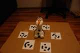 Top good mesh
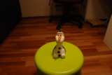 Top Bad mesh
 - For Good mesh: I used tripod, For Bad mesh I did not
- For Good mesh there is the pattern beneath, but not for the Bad mesh
- I used a better camera for the good mesh, which also gives a better angle

Sense: Story of a failure
I also tried to get a model using Sense, with the help of Heidi. The setting was as follows: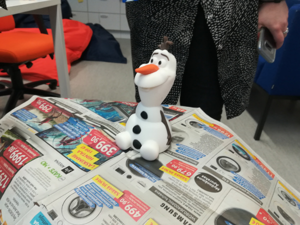

Reflect on the processes
First, about 3D printer. I just would have loved to have one of these some years ago. I am quite used to fast prototyping with software and mobile phones and, when needed, with paper and cardboard. But with a 3D printer, you can get small prototypes fast and easy! This is a huge advantage. And for not very high cost. Also, there are some limitations, like size or type of materials used (mostly plastics). But it is great for testing designs. And for printing yourself the design you want. This last one is good and bad at the same time. Good, because it allows the user to have certain customization. Bad, because anyone can do that, which may lead to violating copyrights. A very interesting advantage of 3D printing is the additive process. This process allow to build one-piece objects (like the one in this assignment) that could not be built in any other way.
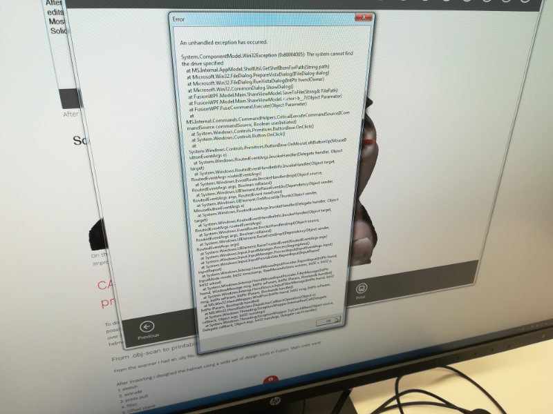
Second, about 3D scanning. I started with this process with a lot of enthusiasm. I think this has a lot of possibilities. Not only for replicating a piece in an easy way, but for alsoeasily modifying it. But I have to say it decay while having to try one an again to obtain a model from the pictures. I had to repeat the process a lot of times to obtain a decent one. In any case, I think that with the correct skills, the replication of a piece is much more easy with this process than with traditional ones, allowing to capture small details that, for example manually, would take a lot of time.
Resources
Once done
Summary
- I have learnt to model something that can only be done with 3D printer.
- I have learnt to print with 3 different printers that use different methods for printing
- sindoh: no different support material, support is done with blocks of material
- fortus: which uses different material for the model and the support. This last one can be removed with ..
- formlabs: no different material for support, but support is done with thin columns
- I have learnt to change the modeling material of the Stratasys printer
- I have learnt the differences in the results of the three printers
- I have learnt that not all the designs work well with the three printers
- I have learnt which settings work /don't work for Photogrammetry
Difficulties
Learnings
- Try MORE to document on the go. This time, I am not going to be able to finish the documentation on time. (And I hate it)
Tips
- For Photogrammetry
- a lot of light
- change background while turning
- object with textures/different colors
- FormLabs: removing the support is not easy so the less support, the better