
Our local instructor this week was Juha Mäkelä
To Do
- Read the ATtiny44A data sheet
- from week 7
- Group work
The "Doing"
ATtiny44A data sheet
Note: The following information is extracted from the ATtiny44a data sheet.
ATtiny44A is a High Performance, Low Power AVR® 8-bit Microcontroller that has
- Advanced RISC Architecture
- 32x8 General Purpose Working Registers
- 12 programmable I/O Lines (8 + 4)
- Operating Voltage 1.8 to 5.5V
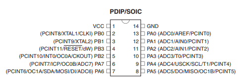
- PB3:PB0 -> bi-directional I/O port
- PB3 has RESET capability.
- to use as I/O, program ('0') RSTDISBL fuse
- As inputs, Port B pins that are externally pulled low will source current if the pull-up resistors are activated.
- PA7:PA0 -> 8 bi-directional I/O port
- As inputs, Port A pins that are externally pulled low will source current if the pull-up resistors are activated.
- A low level on this pin for longer than the minimum pulse length will generate a reset
Programming the board
Understanding Registers & Programming
Writing/Reading from registers
- A pin is set => 1
- A pin is clear => 0
- DDRA/DDRB (Data Direction register): Define the direction of a pin
- If a bit in the DDR is set (1), that pin is an output
- Write to an output pin using: PORTA/PORTB
- If a bit in the DDR is clear (0), that pin is an input
- Read from an input pin: PINA/PINB
- If a bit in the DDR is set (1), that pin is an output
- ~ NOT
- & AND
- | OR
- ^ XOR
- << SHIFT LEFT
- >> SHIFT RIGHT
R = R | (1 << j)
R = R & ~(1 << j)
R & (1 << j)
R = R ^ (1 << j)
Programming with AtMel Studio
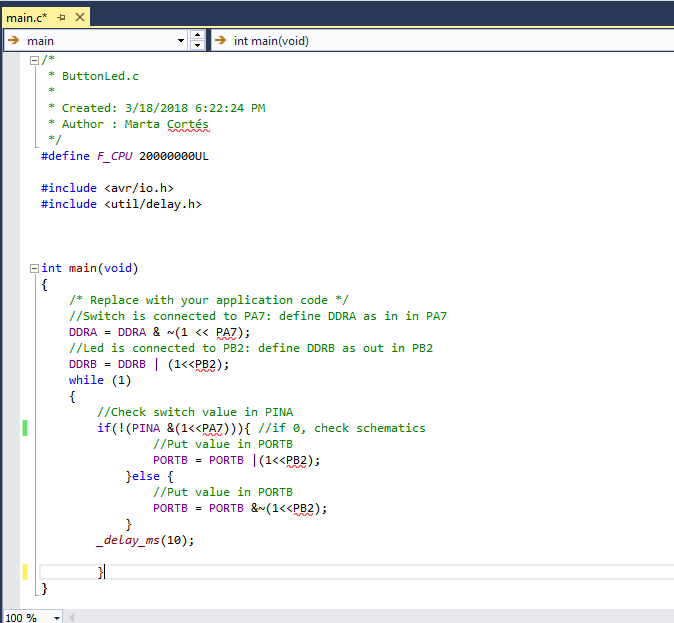
In week 7 (Electronics design) I already used AtmelStudio for compiling and program my board. I start by creating a new project
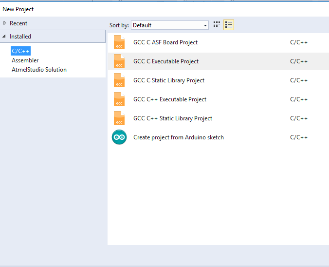
File > New Project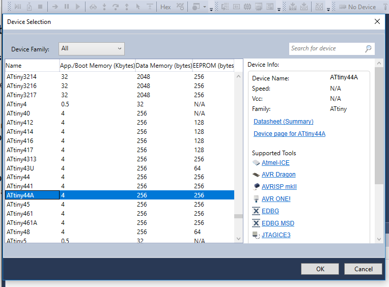
Device selection: ATtiny44A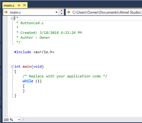
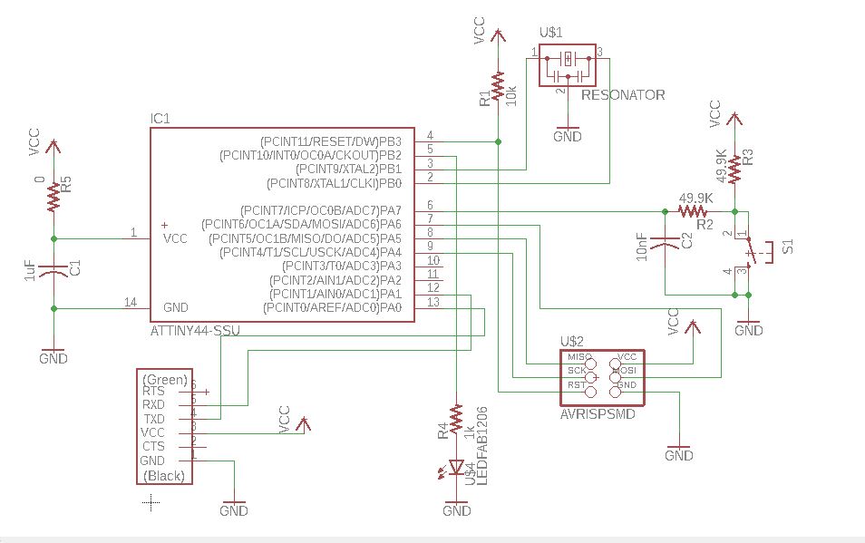
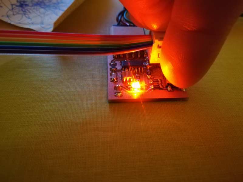
- Led is connected to PB2 (Leg 5)
- Led is an output device => Set bit in DDRB
- Led will light up when output PB2 is set => set PB2 of PORTB
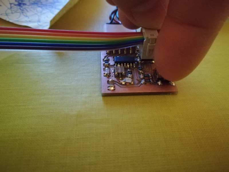
- Switch is connected to PA7 (Leg 6)
- Switch is an input device => Clear bit in DDRA
- When switch is pressed, input PA7 is GRND => read value of PA7 of PINA is 0

Programming with Arduino IDE
First, download Arduino IDE and install it. Then, we need to add support for ATtiny44A board in Arduino IDE. For that:
- Open Arduino IDE
- (Figure on the Right) In
File > Preferences, add toAdditional Boards Manager URLsthe URLhttps://raw.githubusercontent.com/damellis/attiny/ide-1.6.x-boards-manager/package_damellis_attiny_index.json - Then, in
Tools > Board:xxx >Boards Managerscroll to the bottom and clickinstall

Tools > Board:xxx we can select ATtiny44A , and put the correct settings (Board: ATtiny24/44/84, Processor: ATtiny44, Clock: External 20 MHz, Port: COM4, Programmer: USBtinyISP) as shown below, before executing Burn Bootloader (that is, programming fuses => Connect the board!!!)
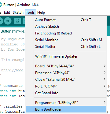
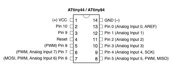
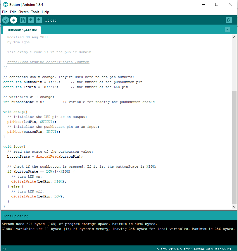
Burn BootloaderFile > Examples > 02.Digital > Button. This example is for Arduino, so the PINS are for it. We need to know the matching pins. From the image bellow and comparing with the pinout of ATtiny on the top of the page:
- Button -> PA7 -> leg 6 -> PIN7
- LED -> PB2 -> leg 5 -> PIN8
- changing the PINs accordingly and also check the switch when it is LOW,
- Upload the code (with the arrow on the top of the file)
- Test!
Programming with Assembler
As I had some time left, and hoping it will not get much time either, I have decided to give it a try. Why? I know that if I do not try now, I won't try this later. Moreover, I had to program in assembler a long looong time ago, so this is an exercise of "how much do you remember?" At this point, I would say that nothing (tags, registers, jumps...). Let's see!
First thing for me is prepare the environment. I noticed in ATmel studio, when creating a new project, I could choose to create an AVR Assembler Project. File > New Project Select Assembler > AVR Assembler Project
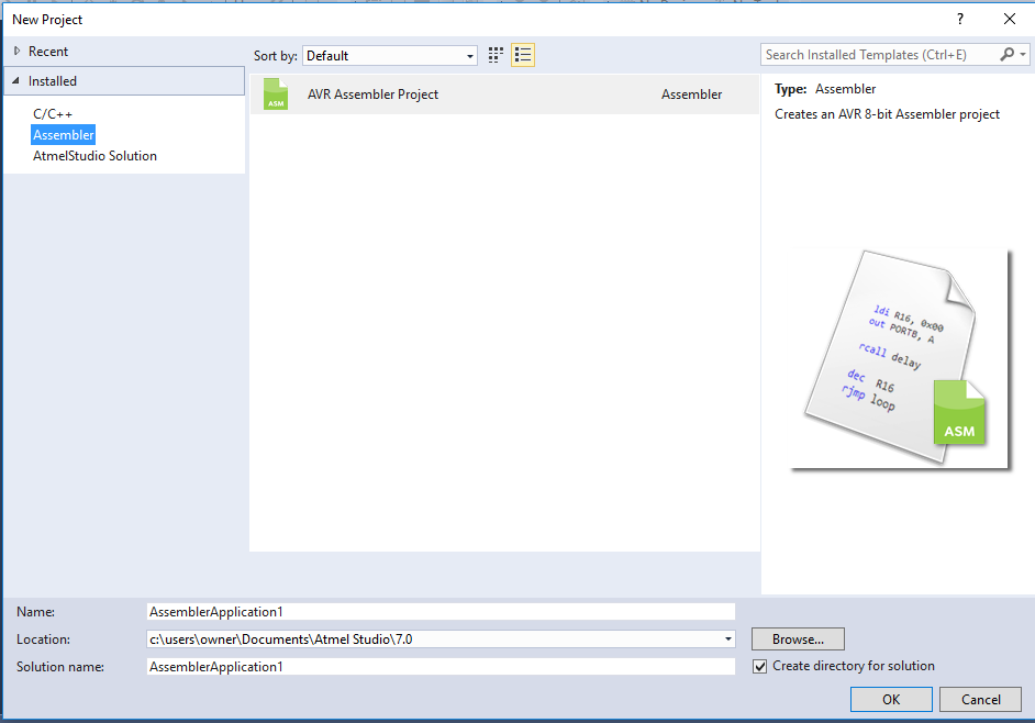
File > New Project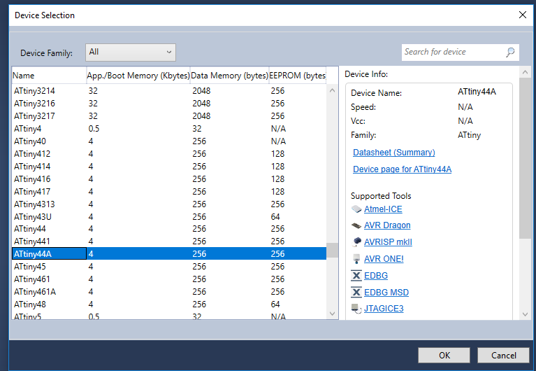
Device selection: ATtiny44A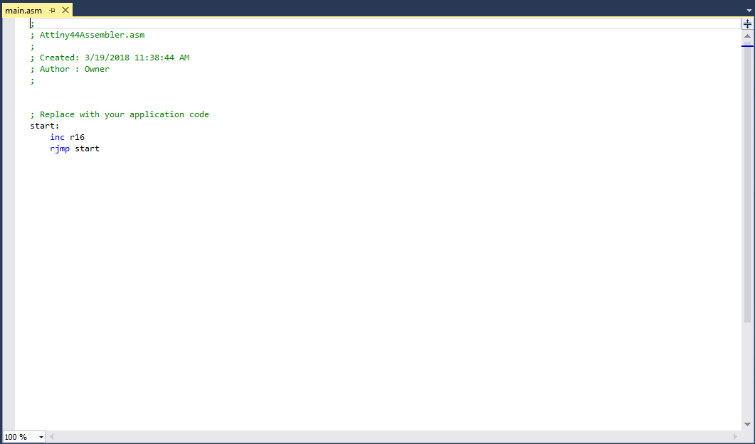
- I need to know how to write in the registers
- I need to know how to do a routine for a delay
- decrement a register?
- loop
- I need to know how to jump to a loop
.cseg: code segment.dseg: data segmentLDI R, value: load register with valueCLR R: Clear register-
OUT P, R: Out Port with R DEC R: Decrement register.org $000: Initialize the stack pointerSBI P, b: Set bit in I/O registerCBI P, b: Clear bit in I/O registerADIW R,k: add immediate to word (affects R and higher R. Eg, R=R4, affects R25 also as high of the word)BRNE k: Branch if Not EqualRJMP k: Relative jumpRCALL k: Relative subroutine call. Remembers the origin for RETRET k: Subroutine return
- 1 clock cycle: 0.00000025 seconds
- Some durations:
- 1 clock cycle: SBI, CBI, CLR, BRNE (if branch not done), LDI, DEC
- 2 clock cycles: ADIW, BRNE (if branch done)
- A delay of 0.5 seconds at 4 MHz equals 2,000,000 clock cycles (which means a delay of 0,1 seconds in my board)
- AVR is an 8-bit microcontroller, the registers con only hold the values 0 to 255
- But!! Registers can be used in pairs=>values from 0 to 65535. The following piece of code clears registers 24 and 25 and increments them in a loop until they overflow to zero again. When that condition occurs, the loop doesn't go around again:
clr r24 clr r25 delay_loop: adiw r24, 1 brne delay_loop- Loop without overflow: ADIW(2) + BRNE(2) = 4 cycles. This is done 0xFFFF times before the overflow occurs.
- The next time the loop only needs 3 cycles, because no branch is done
- This adds up to 4*0xFFFF(looping) + 3(overflow) + 2(CLR) = 262145 cycles. Which means: 2,000,000/262,145 ~ 7.63
- We need to create a loop "around" that loop which will contain our 262,145 cycle loop.
- For fine-tuning the inner loop we need to change the CLR instructions to LDI so that we can use a different start value than 0.
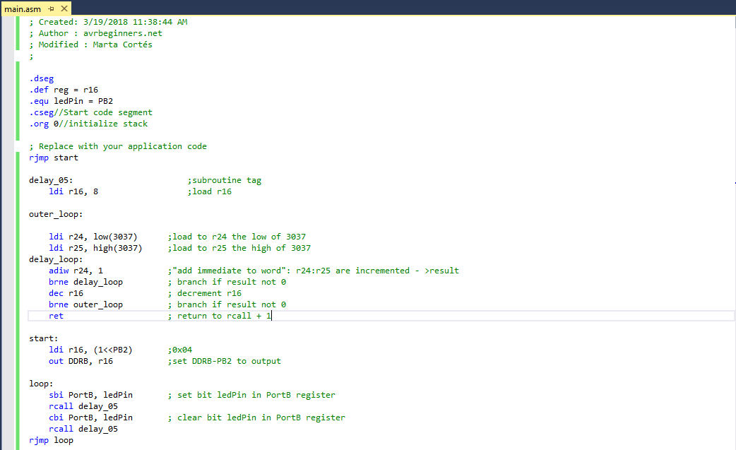
- The "outer" loop will be down-counting from 8 (7 would not be enough, see later) to zero using r16. This is how the delay code looks now:
ldi r16, 8 outer_loop: ldi r24, 0 ldi r25, 0 delay_loop: adiw r24, 1 brne delay_loop dec r16 brne outer_loop - The inner loop is now treated like one BIG instruction needing 262,145 clock cycles. LDI needs 1 clock cycle, DEC also needs 1 clock cycle and BRNE needs 1 or 2 cycles .
-
The overall loop needs: 262,145 (inner loop) + 1 (DEC) + 2 (BRNE) = 262148 * 8 = 2097184 cycles plus the initial LDI = 2097185 . Wait. Subtract one because the last BRNE didn't result in a branch, so it needs 2097184 cycles. (Note, if r16 would down-count from 7 => 262148 * 7 = 1835036 cycles plus 1, not enough)
- This is more like what we want, but 97184 cycles too long. This is where the fine-tuning comes in - we need to change the initial value of r24:r25.
- The outer loop is executed 8 times and includes the "big-inner-loop-instruction". We have to subtract some cycles from the inner loop: 97184 / 8 =12148 cycles per inner loop. This is what the inner loop has to be shorter. Every iteration of the inner loop takes 4 cycles (the last one takes 3 but that's not so important), so let's divide those 12148 by 4. That's 3036.5 or 3037 less iterations. This is our new initialization value for r24:r25!
Resources
Once done
Summary
- I have read a bit more (not all) the ATtiny44a data sheets
- I have reviewed some C for handling registers and bits
- I have generated some short C code for my hello board
- I have programmed my hello board again with ATMStudio
- I have downloaded and get first contact with ARDUino
- I have programmed my hello board with Arduino IDE
- I have programmed my hello board with Assembly language
Difficulties
- I was a bit lost, as I could not attend the introductory class by our local instructor. And I got stressed as I directly dived into the group work, which started as a failure. But at the end, it was not that difficult to start programming
- Main difficulties came with assembly language. For this part of the task, I needed to start with already made code. That is, it was difficult to start a program on my own. But understanding it was great
- I still do not know how I could debug with ATmelStudio
Learnings
- I am most probably not going to program in assembly. But I've learnt you can add assembly into C code. Good to know, just in case!
- Assembly code helped to start thinking again about clocks and cycles
Tips
- This time, I programmed the small snipped of C from scratch. To see if I had understood. But I need to go through all those MACROS out there
- ATmel studio is a good tool.
- Again, ATtiny44a data sheet. Pretty sure I will go back to it