
Our instructor this week was Antti Mäntyniemi. This week we need to design a micro with an outpout. We have to make something do something. I have decided to go with Charlieplexing. I have a lot of LEDS in my final project, and up to now, I am going on using ATtiny44A. So I think it will be good to learn how to handle multiple LEDs with small amount of pins. Also, I know there is neopixel, and I might use it at some point. But I feel chalieplexing will allow me more flexibility on where to put the LEDs. I want to try to do a tower of LEDs. Basically, I am experimenting a bit on LEDs
To Do
- Understand charlieplexing
- Understand how to build the tower of LEDS
- Design the boards and mill them and solder them
- Program
- Group work
The "Doing"
Charlieplexing and The Tower
- 3 possible states of the pins: High, low and High resistance
- Persistence of vision
- The LED working curve, with the different areas: no glowing, dim, operating, burnout
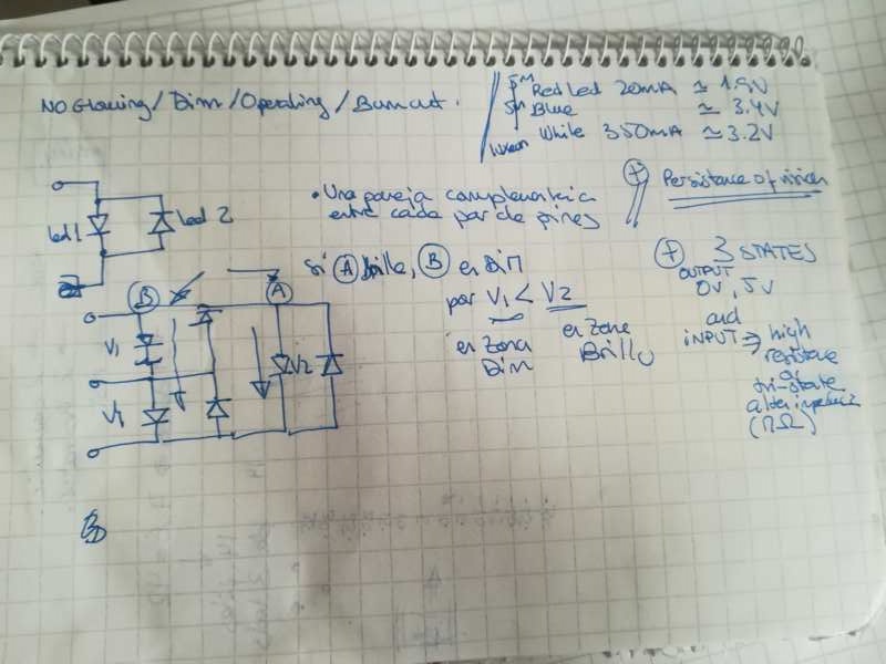
Understanding Charlieplexing
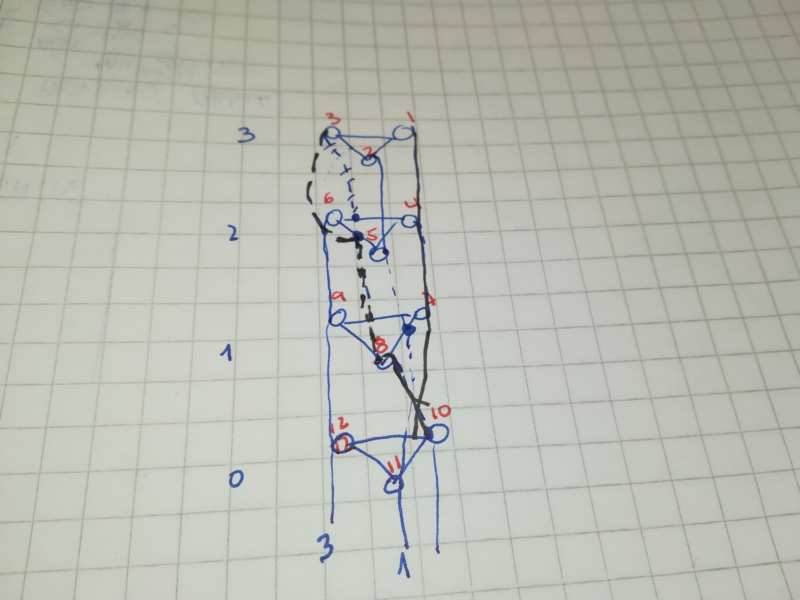
Understanding how charlieplexing works has not been the most difficult part. For me, the challenge was in building the tower. So, how to build it not getting crazy with the connections?
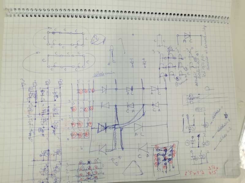
Checking other's work for creating cubes, I managed to understand how to create a clear schematic for identifying the different LEDS and lines.
Creating a circuit and transferring to 3D design
Then, I have decided to use 4 pins of the ATtiny44A as starters. This means I can use up to 4*3 = 12 LEDs. So I create the schematic, 2D view structure and "3D" view structure for 12 LEDs.
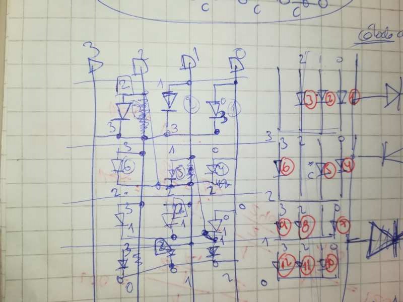
Plane circuit

Trying to build layers
A bit more 3D vision
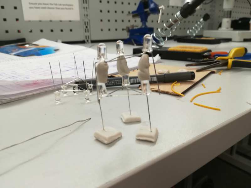
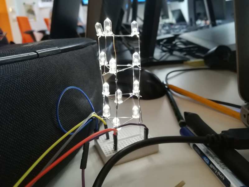
Building the tower
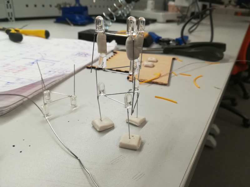
First, to solder the LEDs together, I need a support for them. The fastest way was to use some blue-tack like material to create a "mould". Then, I solder each layer, for a total of four.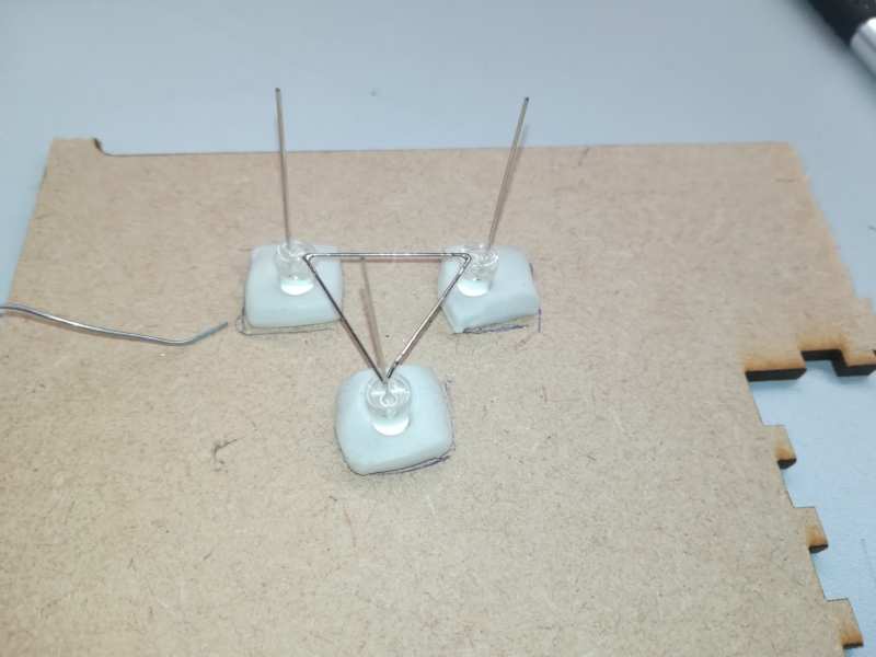 Then I can start to solder the layers together. I have to go layer by layer, checking the connections from the design above.


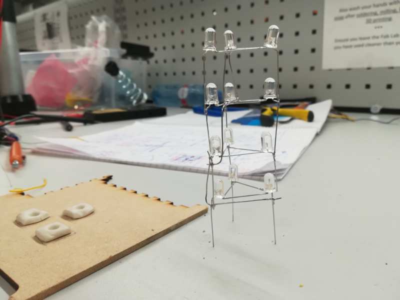 I would need to plan a bit better the connections next time.
Design, milling, soldering
I wanted to link this to the input board, but I decided to also make a board with a button, to interact with the output, and later link the two boards.
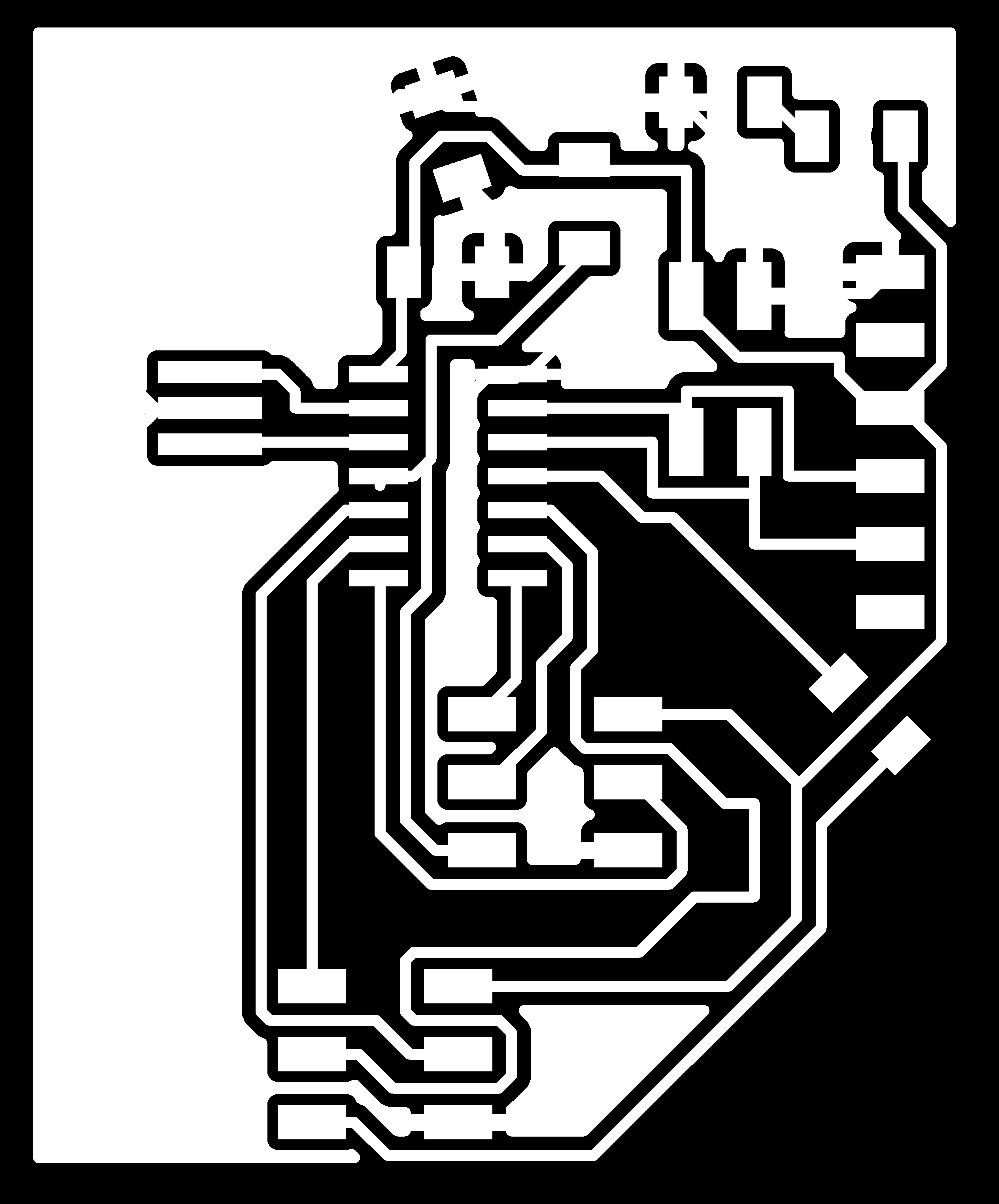
Microcontroller board
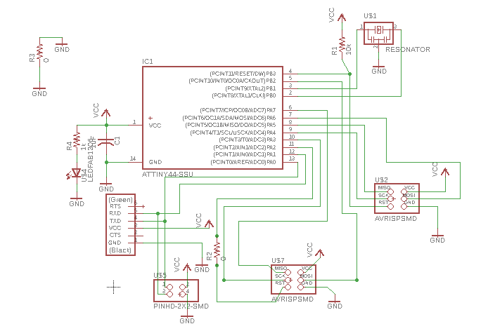
Schematic
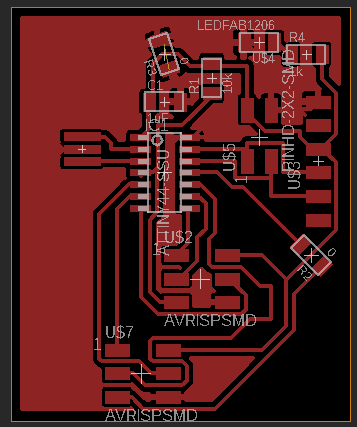
board

Schematic

Board

Schematic
Board
Too much removed
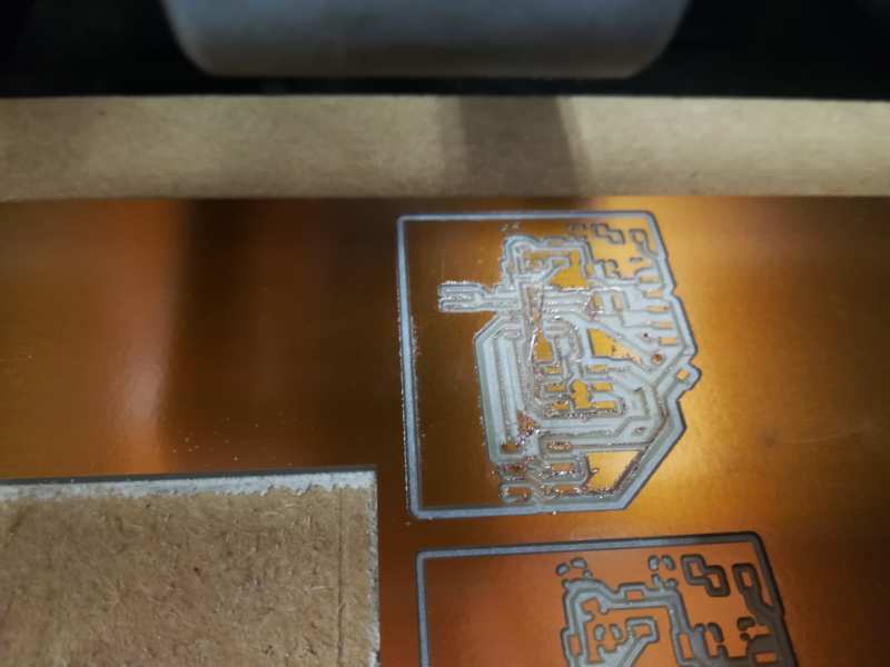
Too much removed, again
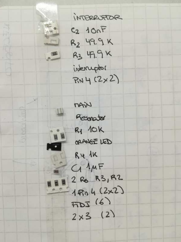
Bill on materials
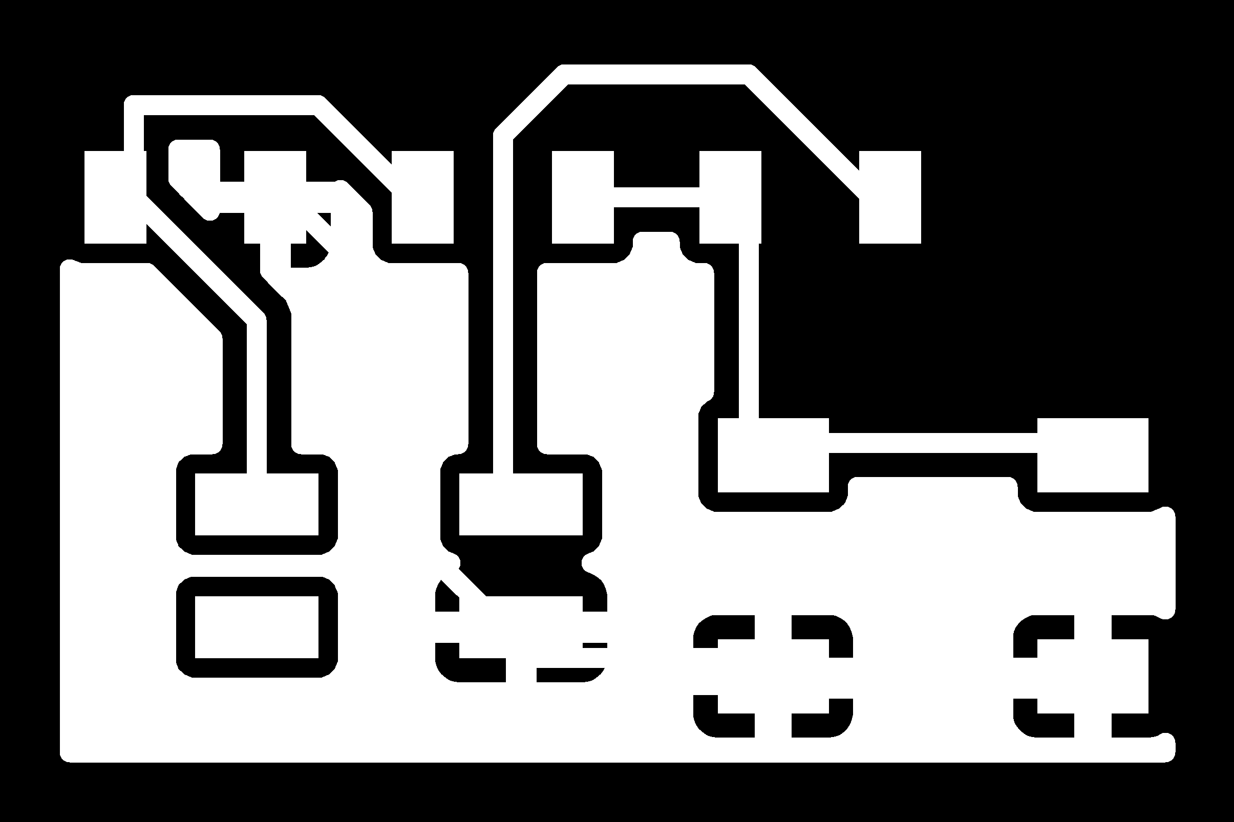
For soldering the resistors board, the bill of Materials:
- 5 110ohms resistors
- 2 3x2 header pins
Program
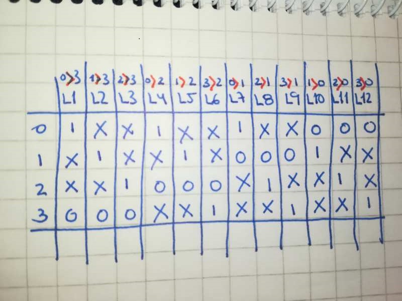
LEDs working table
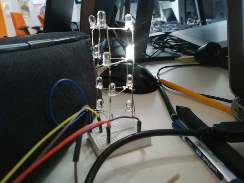
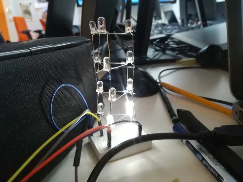
As I said, In a future I want to connect this board to the one from input. But first, I start adding a push button. I am quite tight on schedule this week. So I decided to test Neil's code for hello.array.44.2.cad. And then start from there and change for my purposes. I just had to change the pins because Neil's code assumes LEDs are connected to pins PA0-PA4, and in my board I am using pins PA7, PA3, PA4, PA5 (ATtiny44a data sheet for pin checking), and put an if-else block for the button, to check if it has been pressed. I started with a breadboard, as I did not have the tower of LEDs built yet. I wanted to test the structure of LEDs first, and then build the tower. I am not adding a picture of that, because it was really a mess of cables a pin heads.
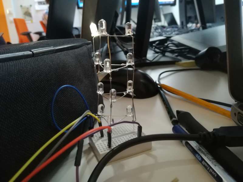
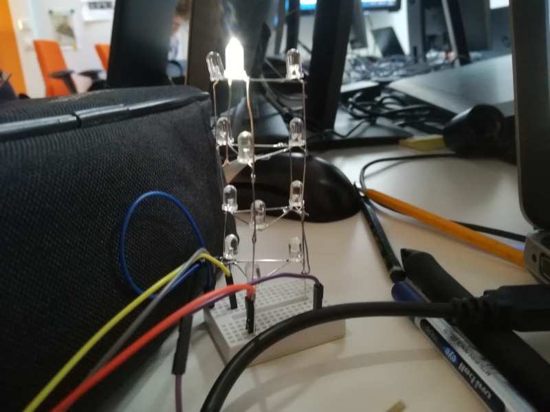
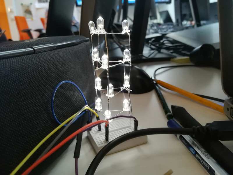
Once it worked well in the breadboard, I moved to the tower of LEDs.


Resources
- ATtiny44a data sheet
- The way Tom's Circuits explain how to do the schematic, helped a lot to understand how to build my tower
- A good link for Charlieplexing theory
- 12 Through-hole white LEDs
Once done
Summary
- I have understood how Charlieplexing works
- I have learnt to create an schematic for charlieplexing
- I have learnt how, with the correct schematic, it is possible to build a tower of LEDs for Charlieplexing
Difficulties
- Time, time, time... (again)
- understand how to build the tower
Learnings
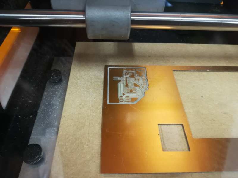
- Take it easy with the milling: things happen.
- Keep on checking shorts on freshly milled boards, even when you do not have much time. This can save a lot of time afterwards.
Tips
- I usually check for shorts in the board before soldering. This time I was in a hurry, and did not do it very well. This a paid afterwards, as I had some shorts beneath a soldered pin head
- To solder the LEDs, it is really necessary to have a mould
Files
- main.c C file for showing patters of lights in charlieplexing when pressing a button
- Eagle board file and Eagle schematic file for the board: microcontroller
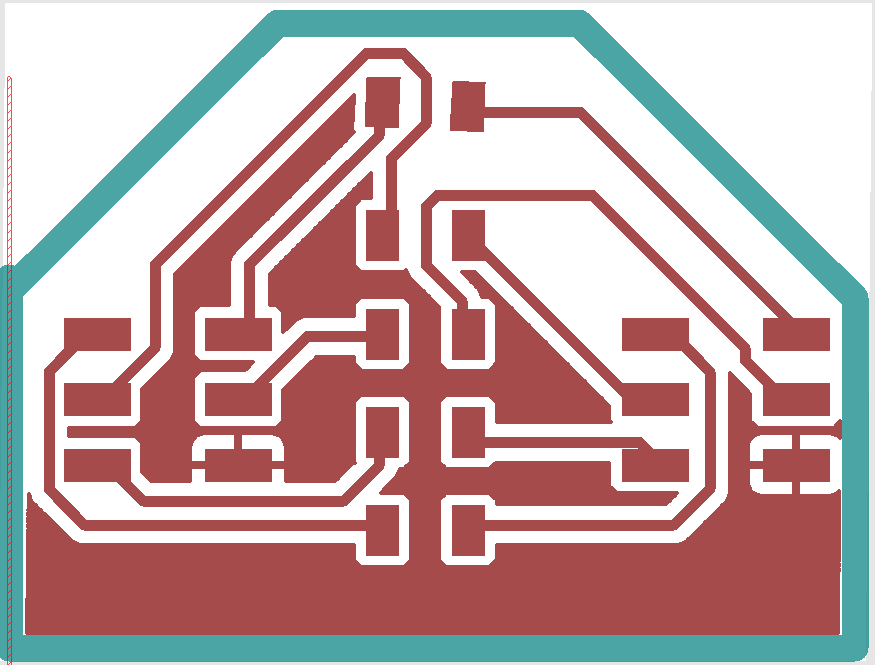
- Outline for the controller board
- Traces for the controller board
- Eagle board file and Eagle schematic file for the board: button
- Outline for the button board
- Traces for the button board
- Eagle board file and Eagle schematic file for the board: resistors
- Outline for the resistors board
- Traces for the resistors board