Mechanical & Machine design
Week 15 & 16 - Mechanical & Machine design
Here you will find my work description during this fifteenth and sisteenth week
General info
Mechanical design
Machine design
Class notes
Group Assignment
Week 15
- design a machine that includes mechanism+actuation+automation
- build the passive parts and operate it manually
- document the group project and your individual contribution
Week 16
- actuate and automate your machine
- document the group project and your individual contribution
After the class we talked about projects. As I knew that I could not be full time involved in the assignement, I decided to be part of someone else project. However I told that I was interrested in working on Jens & Co CNC machines. I talked with Kris that explained to me his profile drilling machine. Basically a CNC to Drill holes in (aluminium) profiles. Those profiles are used to assemble artistic video matpping structures.
You can check his work on youtube:
I saw a relation with Jens CNC and I propose them as a starting point for his project. Kris looked enthusiastic. That is why I decided to be part of his team.
Profile milling machine
My role in those two assignement
At the beginning I was focused on the machine design. Kris was responsible of the documentation and Andres was responsible of studying the mechanics.
We work together on the idea, then I started making the cardboard version. Afterthe I designed the gantry and the X and Z axis studying the Jens’s rack and pinions system. I milled the main frame at my fablab with kris. I milled the HDPE X,Z system. I mount all the parts. I debug the structure skrewing and drilling extra parts. I also debug the electronics with andres then I assembled the electonics made by andres onto the machine. Then I designed and printed the tool holder. Finally I setup the firmware and tune the setting in order the machine can run some gcode.
At the end I touch all the parts of the machine and mechanical design assignement.
– Go to project page –
State of the art
After a few exchanges we decided to start studying the Hattori - Small CNC from fellesverkstedet.
Project managment
Ideas to discuss with kris
- Trello for tasks - No
- Whatsapp/slack - WhatsApp
- Gitlab (obviously)
First day - Welcome Andres !
Kris gave a fusion workshop the thursday morning.
A new team member came up the first day, he’s Andrés Tuells.
Design thinking
I am a big fan of the design thinking approach. In a few words, we need to think the machine for/with the end users.
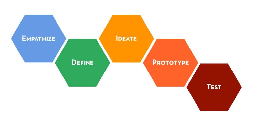
The plan:
- Empathize (Who will use it, how they imagine the usage, the machine)
- Define (what the machine should do, what are the constraints)
- Ideate (any ideas, what to improve)
- Prototype (choose some ideas, make first version)
- Test (show them, iterate)
First step : kris explained what the machine is for, he showed some designs, and how shuch a machine can help hime making greater structures.
.jpg)
Define & Ideate : I proposed to realize as our first task a cardboard version of our machine. Thos will allows us to evaluate the machine size and the components we will need.
After we decided how will be the machine I sketch it on Sketchup as reference.
.jpg)
Then quickly draw it on cardboard.
.jpg)
cut it and assemble all the part (some tape needed).
.jpg)
Using the low-tech tool.
.jpg)
And showing teamates how they work.
.jpg)
In my own opinion it was really usefull to build this cardboard version, it allowed us to place the motors for exemple.
.jpg)
Machine documentation
Design
I invited kris and Andres to come in Perpignan for 2 days (monday and tuesday) in order to work together on the design of the machine. Unfortunatly Andres was not enabled to come. So we suggest spliting (just for 2 days).
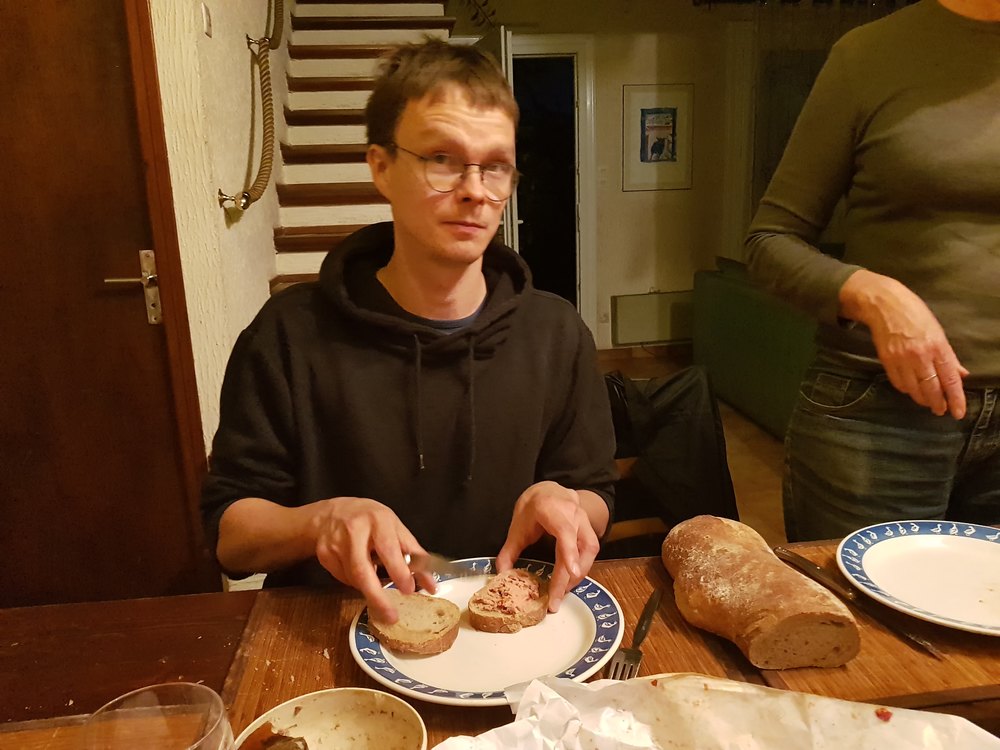
Kris eating some french paté.
How we divided the work:
- Andrés worked on electronics starting studying how a grbl shield works.
- Kris designed the machine main frame
- I worked on the gantry studying the Jen’s rack and pinion system
On Monday kris arrived in Perpignan for a 2 day design session.
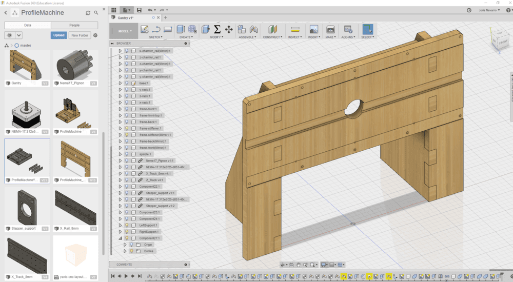
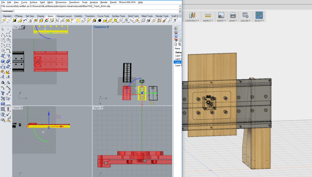
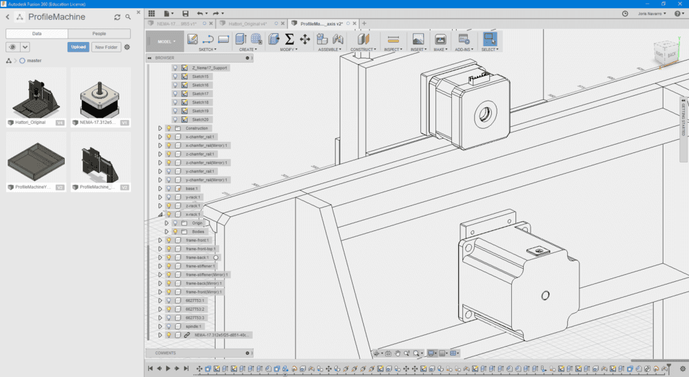
Kris is confortable with Fusion, I am not as confortable as him, but want to improve my skils on it. I integrated the generate parts from rhino to fusion in order to have the whole design on fusion.
I started studying the Jen’s parametric design made with Grasshopper.
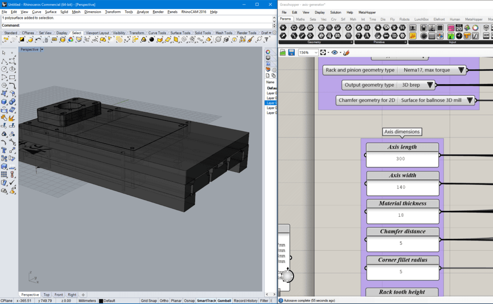
Playing with all the available parametric sttings to guess what they are for. Until I find the the rights settings to use depending on the material we are going to use.
I tuned the GH definition and exported parts as STEP files. I imported them into fusion.
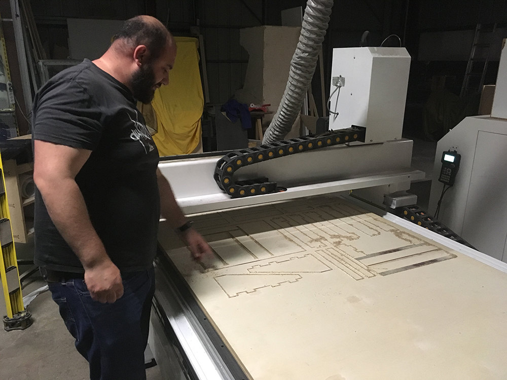
Then Kris and I exported the final model to DXF file. I used V-Carve as CAM software to genrated toolpathes for the main frame.
fabricating
We use the CNC of the FabLab Perpignan to mill the frame and the gantry. So we have the main structure of the machine.
Funsion inergration of STEP files.
Wea also 3D print some parts like the bearing holders.
On Wednesday, Kris and I were back to barcelona, just in time for Neil class. Andres was in trouble with the electronic part and we tried to help him understanting what was wrong. Xavi also tried to give a hand but unfortunately on wednesday, none of the motors move.
On thirday after having tried all drivers, all microstepper configurations (we started becoming experts) we (Andres) finally find out that the wiring of the inner coils were misunderstood, probably due to a missing reference of the Nema17 stepper.
On the same day, I started studying the Jen’s Rack and pignon system to mill it using a leftover of HDPE material found (nobody knew who was the owner of this material).
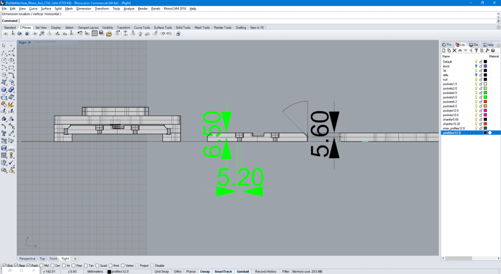
According to the model we made on fusion, I generated in Rhino/Grassopper a full X-Z axis system for the 8mm thick HDPE material I found. The started creating the startegies under RhinoCAM in order to mill the rack and pinions with HDPE.
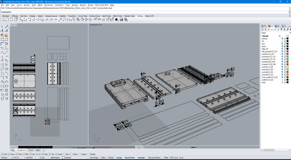
Back to rhinoCAM to create startegies for milling the HDPE.
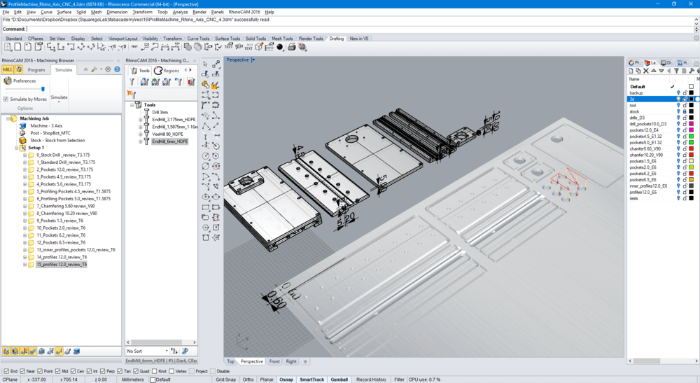
Finally I finished the strategies only the Thisday of the next week 14 strategies. Finally I milled all the parts on the friday, when I found, the bits needed (3.175 mm, 1.85mm, 90° V, 6 mm). 2 hours of of milling, 3 tool changes, but the result is satisfying.
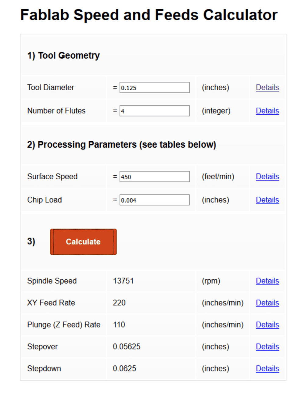
For the feeds and speeds I used the Fablab Speed and Feeds Calculator and the jake Read’s machine week document.
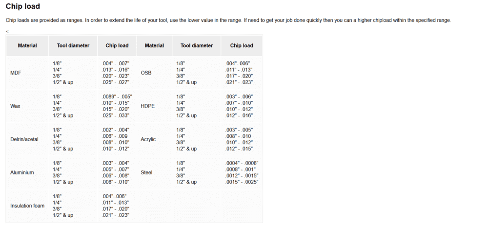
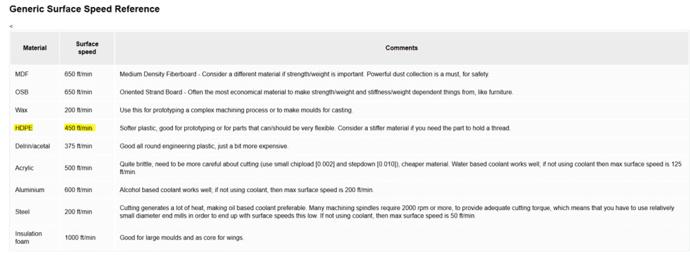
Here is a resume of the strategies:
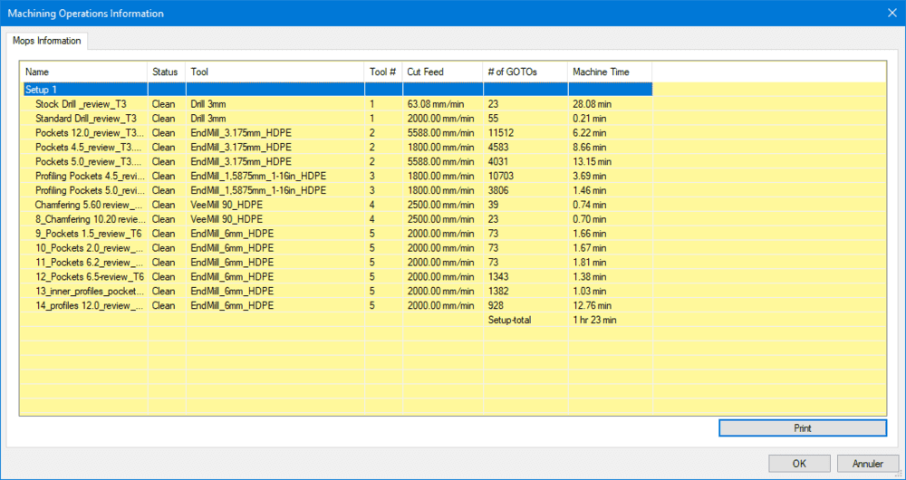
And some videos showing the milling process:
Look at those awesome chip loads !!
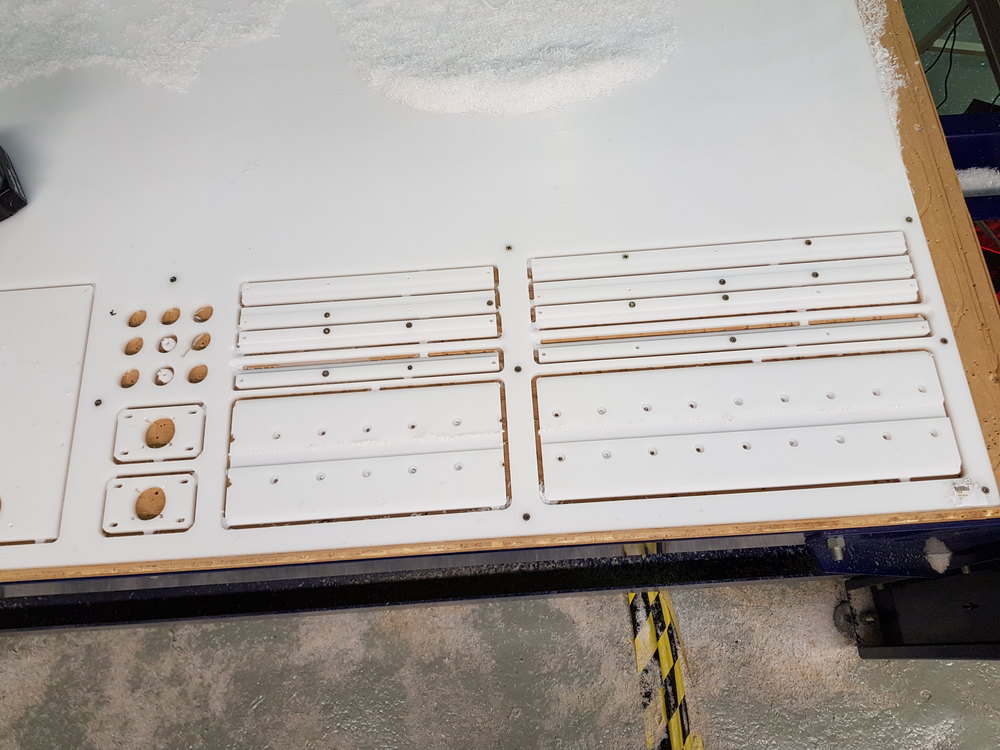
Here is the result. Really proud of myself, getting more and more confortable with rhinoCAM/shopbot.
Assembling
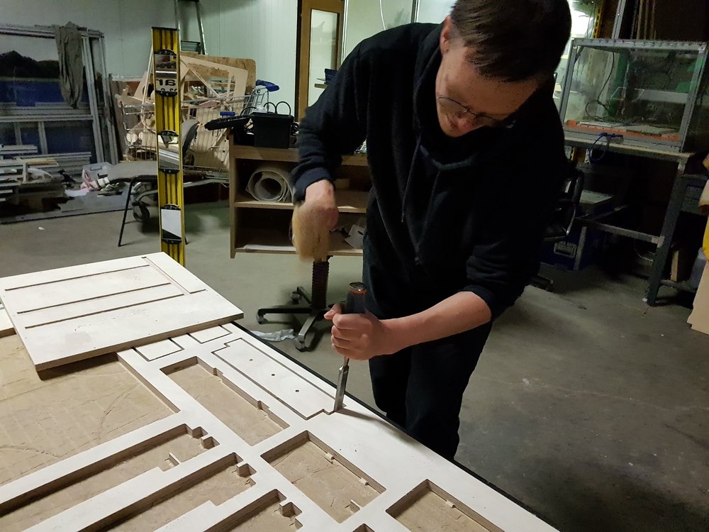
The most difficult part of the assembly was to find the bolts, the screws and the nuts. At the end of the day, Santi came to “Chino” to buy some little bolds. I think he was tied of me asking him every 5 minutes where I can find something (Santi, if you read that, I am sorry).
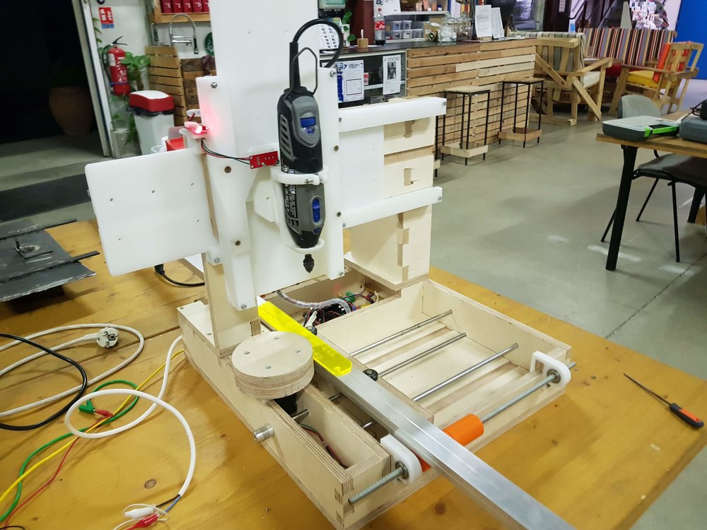
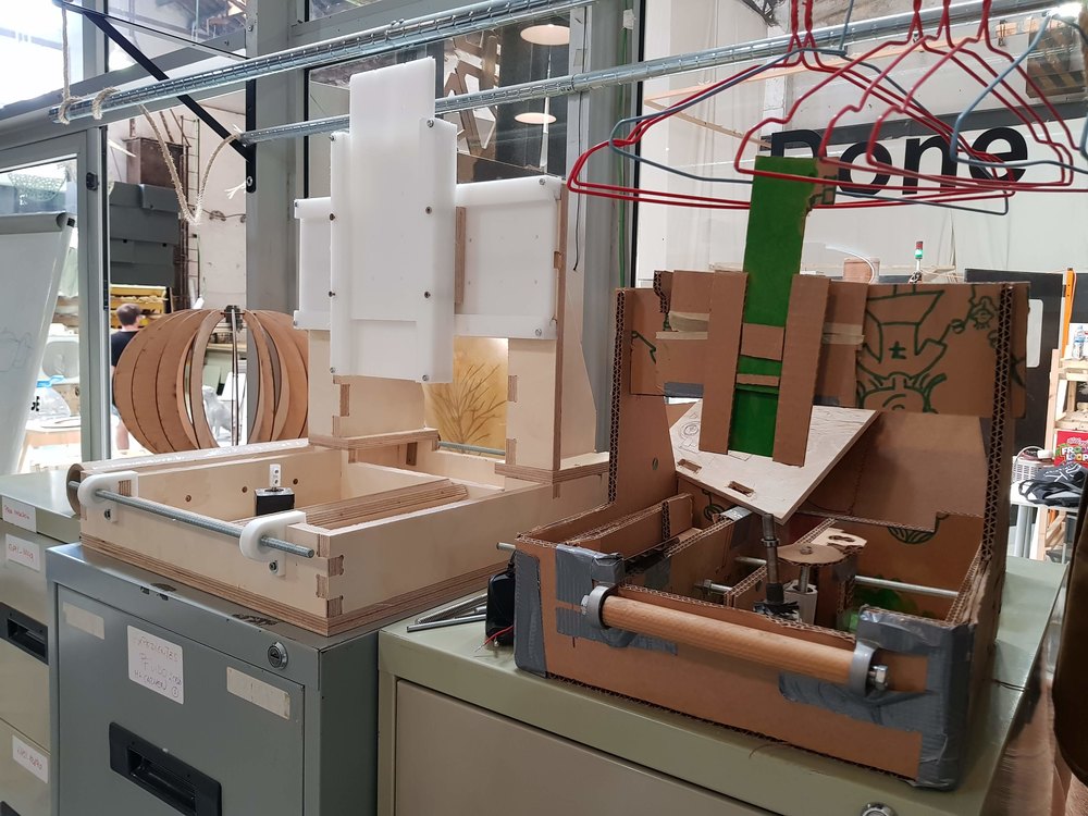
Finally, we make some manual adjustments drilling screwing and cutting, and we had this first version of the frame.
Here you can see the result at cardboard version’s side.
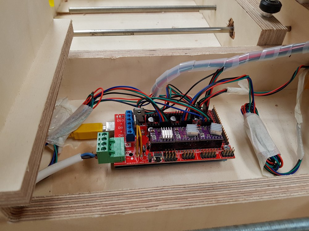
The week after Kris couldn’t be available bacause he had to travel to give workshops. Andrés was still working on the electronic and the command. He swithed to Ramps. And ha was still fighting to tune the motors. He suspected the motors tobe the cause of the troubles so he orederd new ones.
After a bunch of test and adjustements, we managed to make it move.
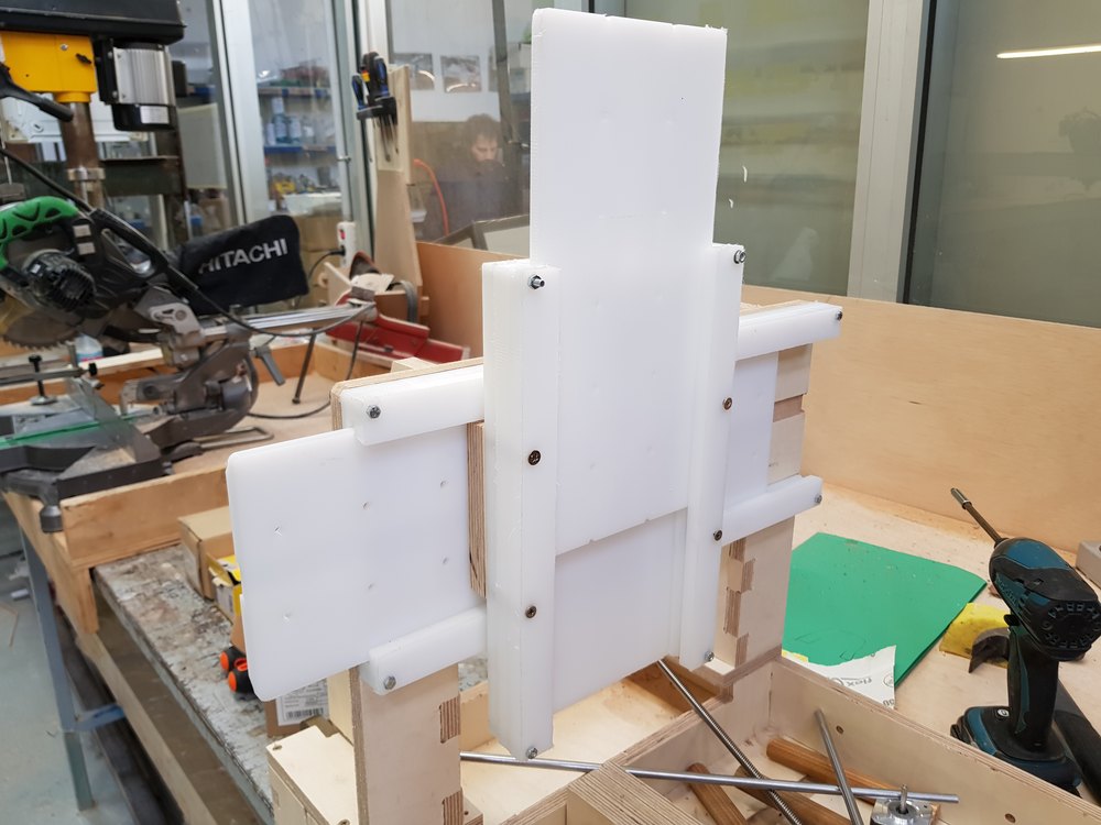
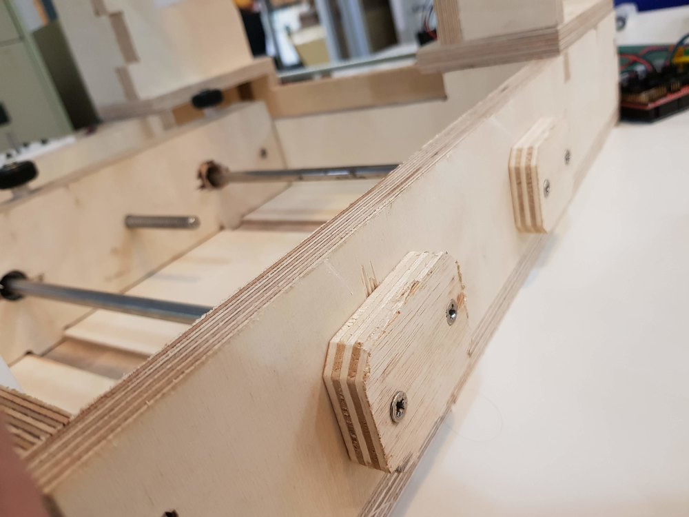
Back to France, I took the machine and continue working on the integration.
This is the Y axis clamp part, using small bearings.
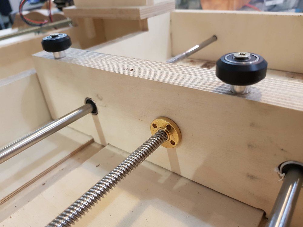
I used some tricks to be able to maintain support shafts.
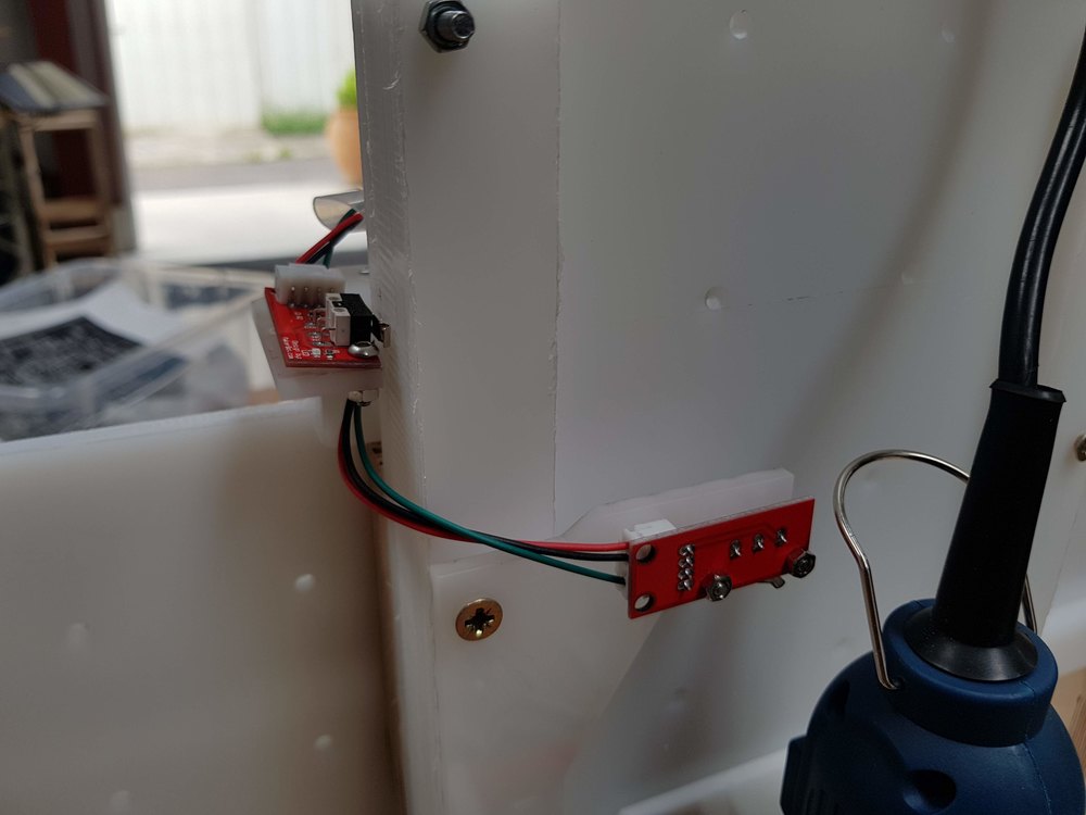
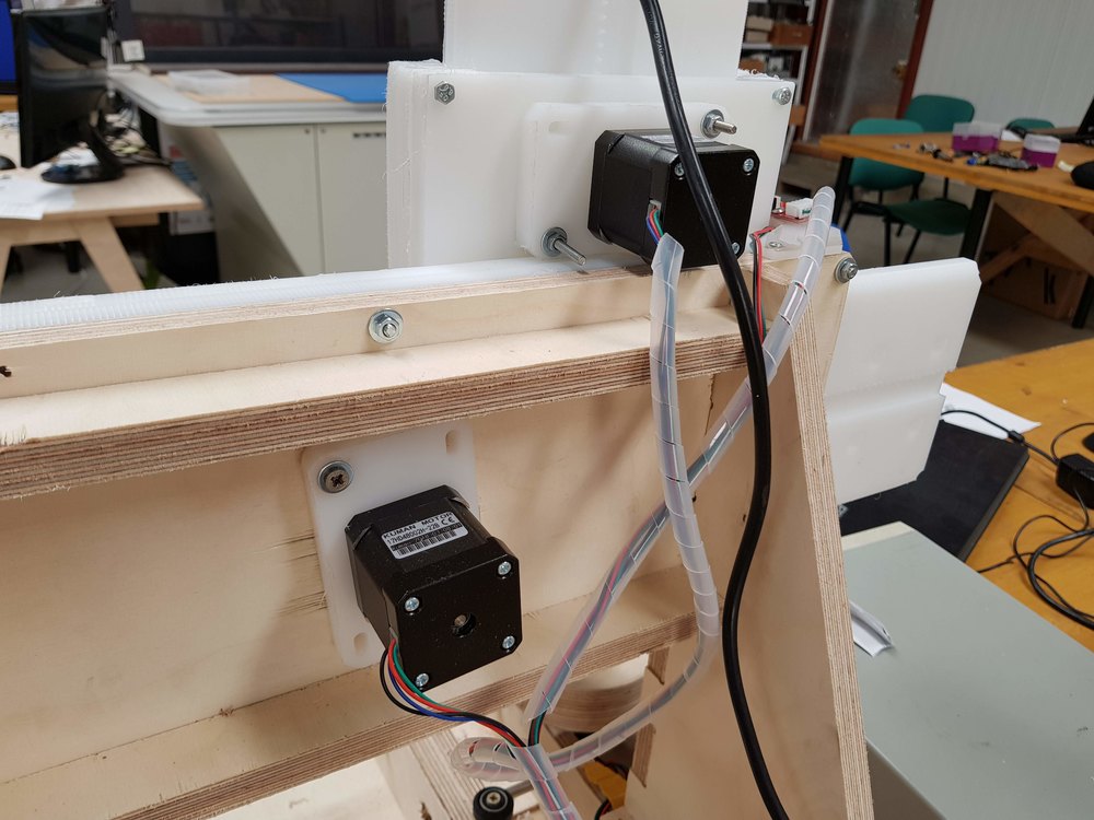
I designed dome parts, like endstop supports, and Y axes wheel with its motor support.
This Y wheel did not work.

I milled in wood the wheel and 3D print a part between the motor shaft and the wooden wheel.

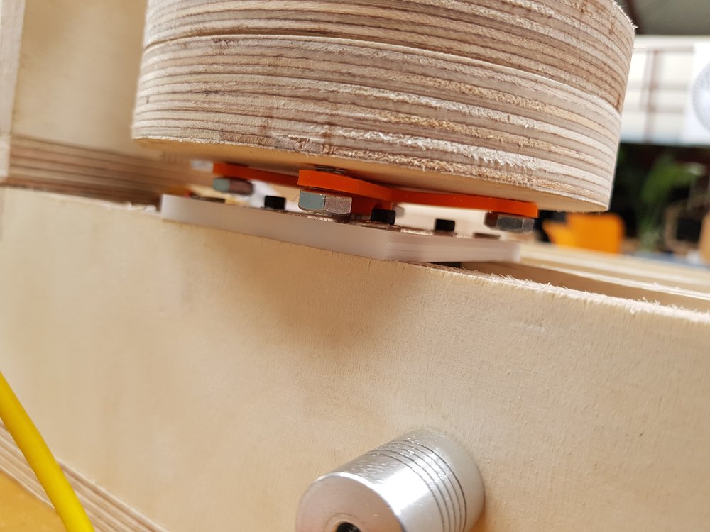
Some times it took several iterations to obtain the good part.
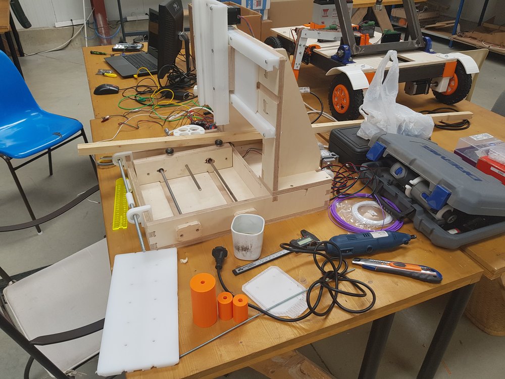
For the tool, that will be a dremel, I found on thingiverse a model, I edit to fit on our system.
Original design : Support for Dremel 4000 by bqLabs - CC - BY - SA
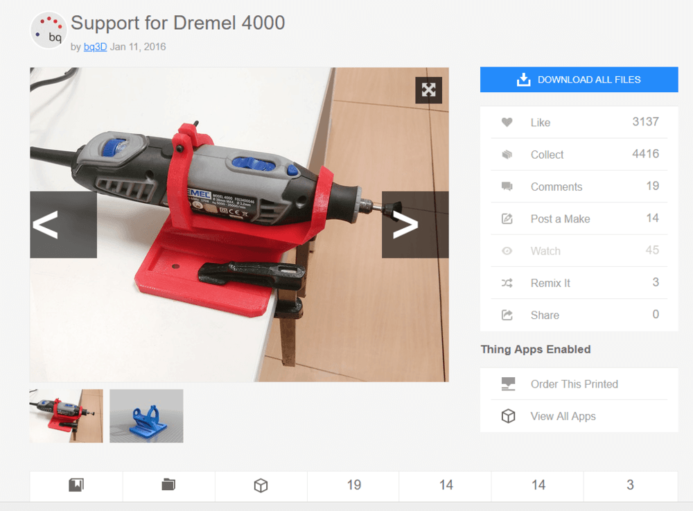
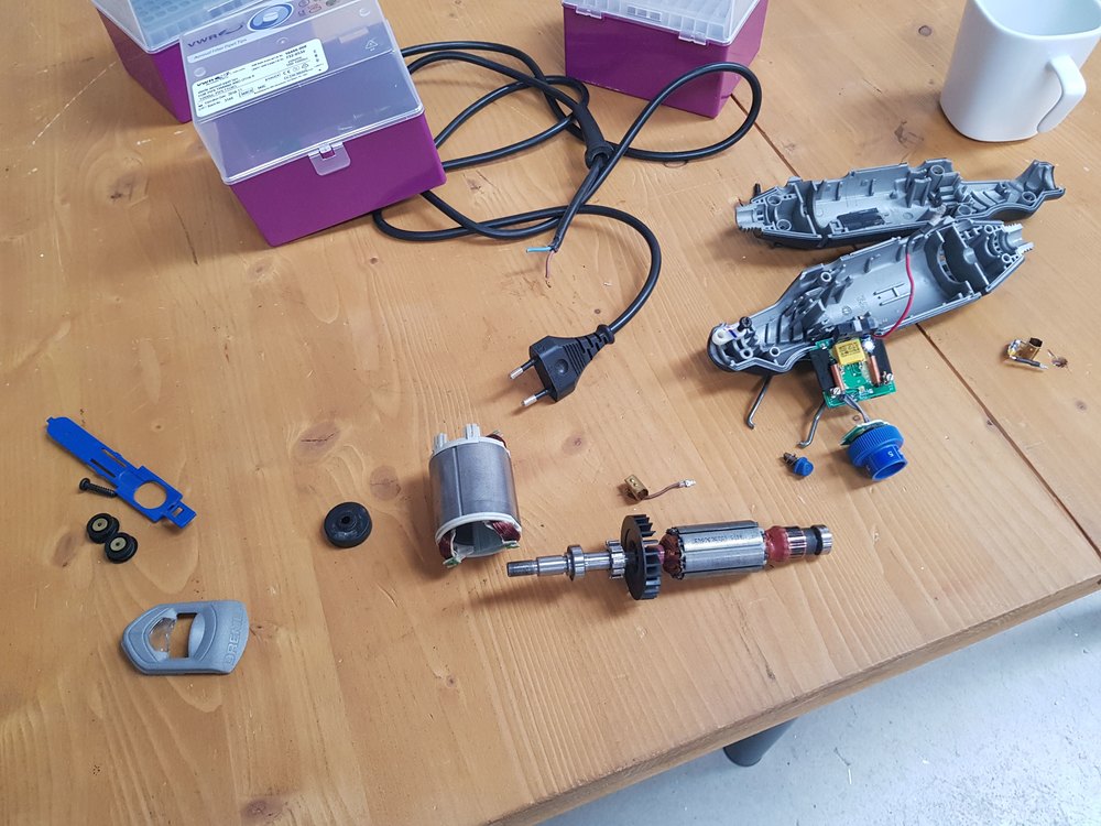
My dremel was broken, we tried fixing it, but the inner coils were burned. So I change by a cheaper, powerless one.
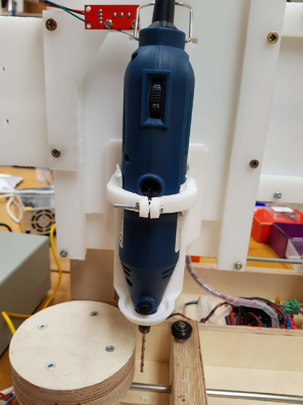
Finally make all assembly clean, with a proper cable management.
Controlling:
I decided to setup a CNC compatible firmware called Repetier. It could have been Marlin, but I knew there is a special integration of CNC machining on repetier, mainly known as a 3D printer firmware.
The firmware comes with a software called Repetier Host
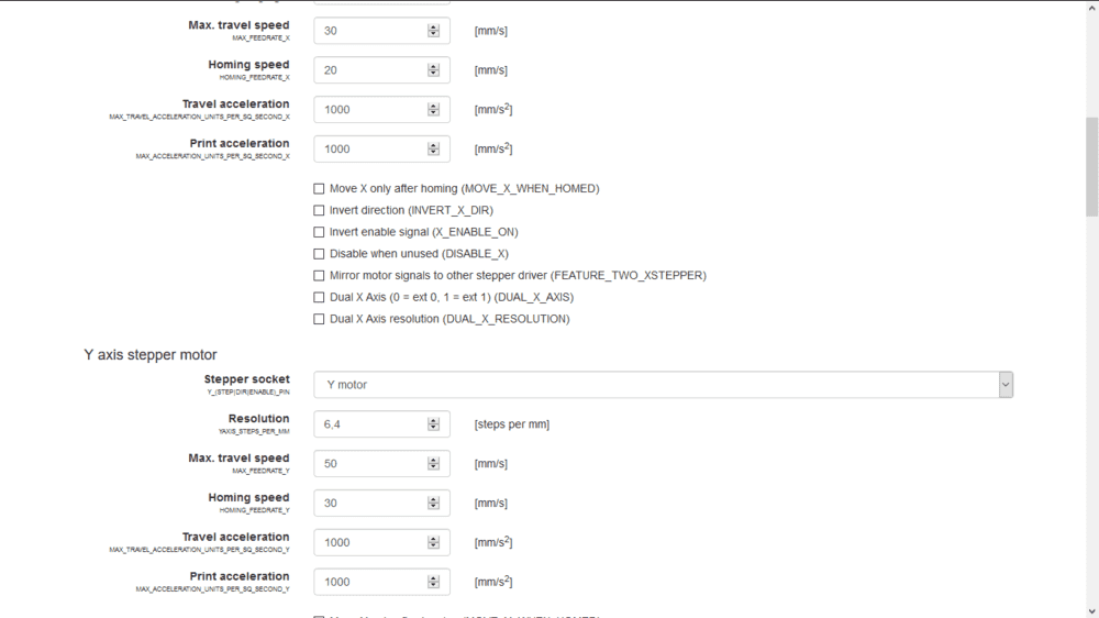
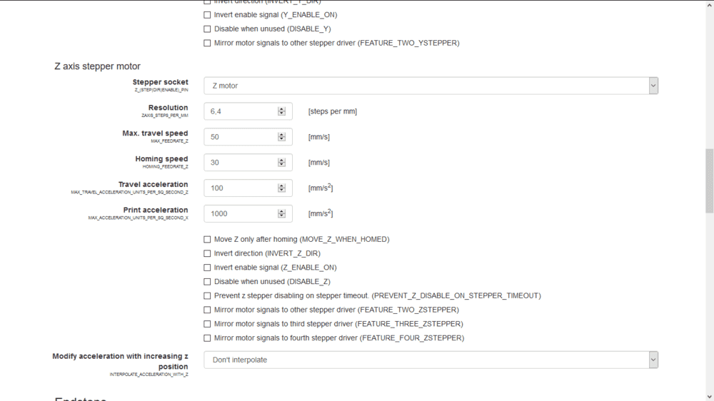
There is a special online Wizard to tune your firmware depending on your machine.
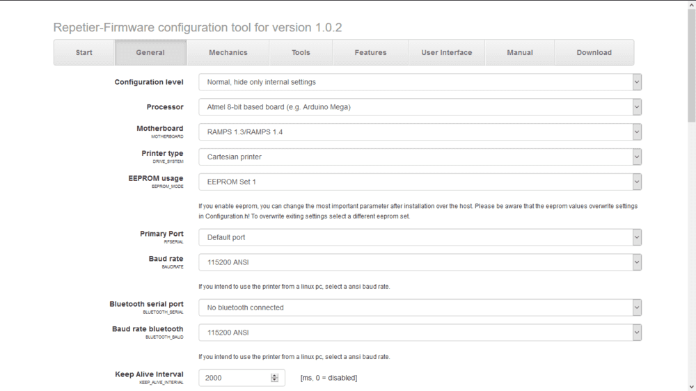
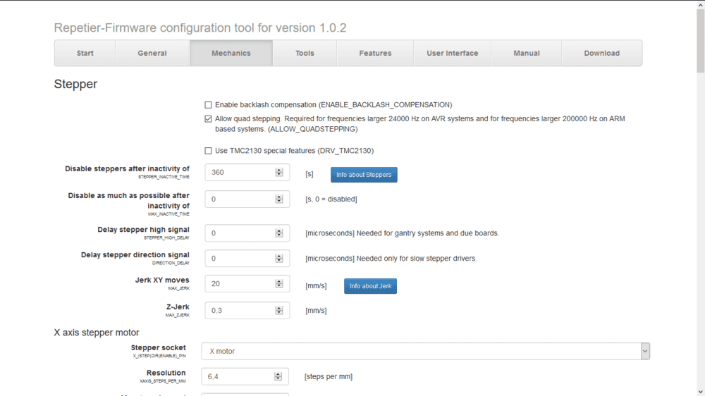
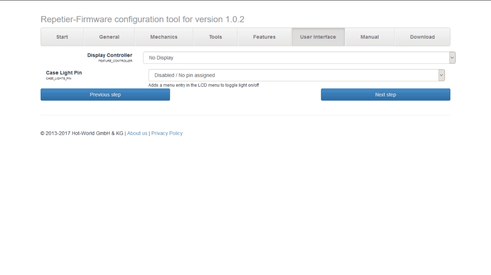
Here are all the steps, you can see the different value choosen :
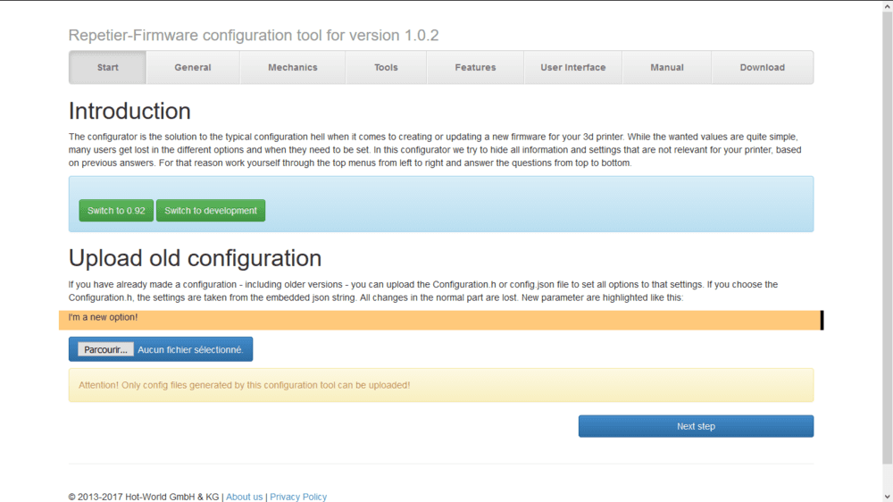
This wizard is easy to follow, just read the values set for CNC machines. What controller are you using ? Arduino Mega + Ramps.
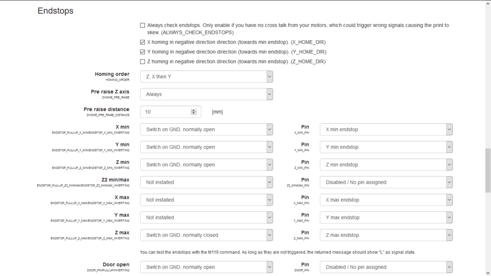
The end stops were probably the most tricky part to configure, because we have an “infinite” Y axis. I had to disable Y endstop.
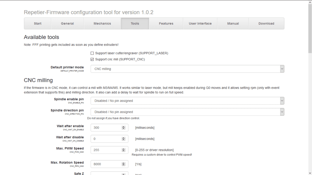
This id the step for defining you are building a CNC (and not a 3D printer).
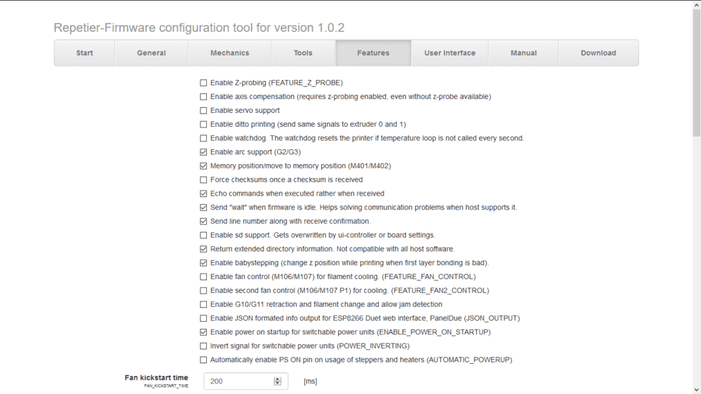
Those settings are commons for CNC machining (like enable Arc Suppport G2/G3). Maybe some (old) controller do not support this option.
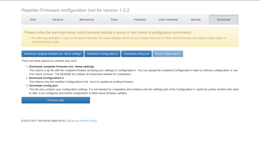
Once you defined your settings, you can download the firmware we put on the arduino mega.
You can download the whole archive (the first time) or just the configuration.h.
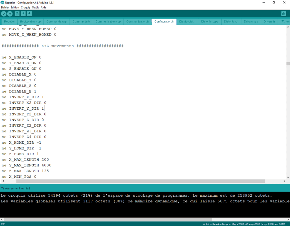
Unzip the archive, open .ino file with Arduino IDE. Connect your ramps and upload the code to the arduino as shown bellow.
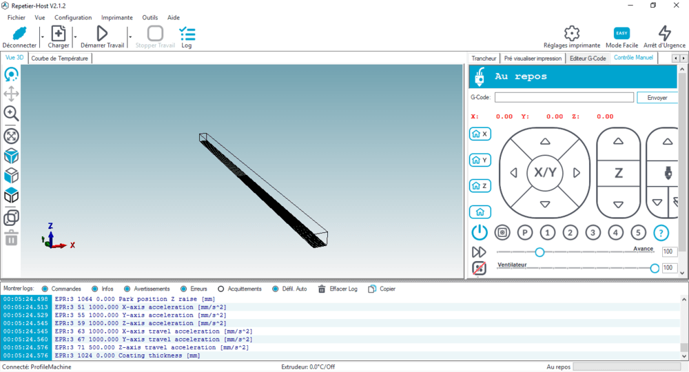
Now dowload and install the Repetier Host that we use for driving the machine manually sending GCode.
The UI look like that.
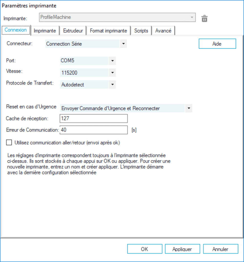
Set up connection settings to connect the computer to the arduino/ramps.
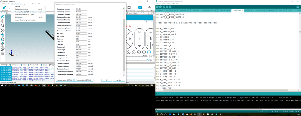
Then I fine tuned the machine settings like the number of step/mm for each motors, accelerations and moves speed. Those values are stored in the arduino EEPROM (Menu->Configuration-> EEPROM firmware configuration).
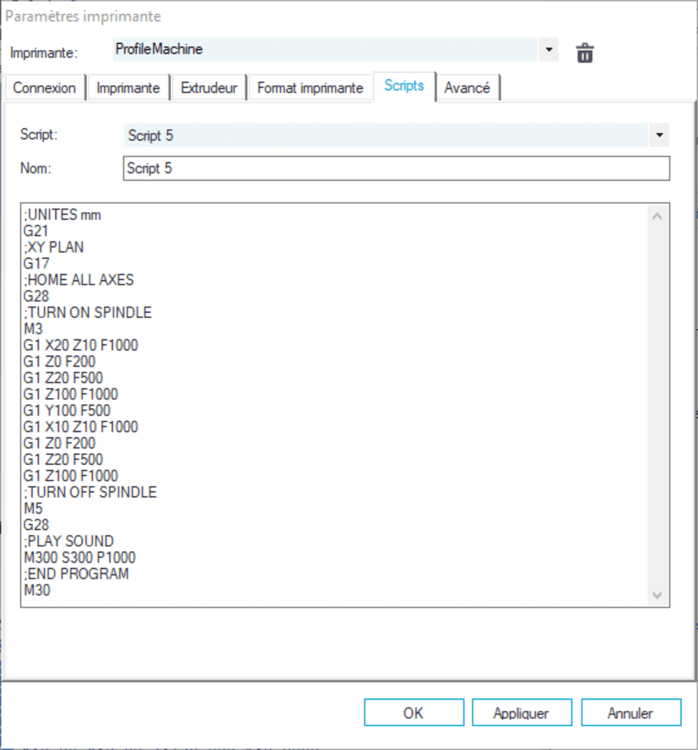
I wrote some g-code to create a sample move, but you could also use your favorite CAM software to generate the gcode.
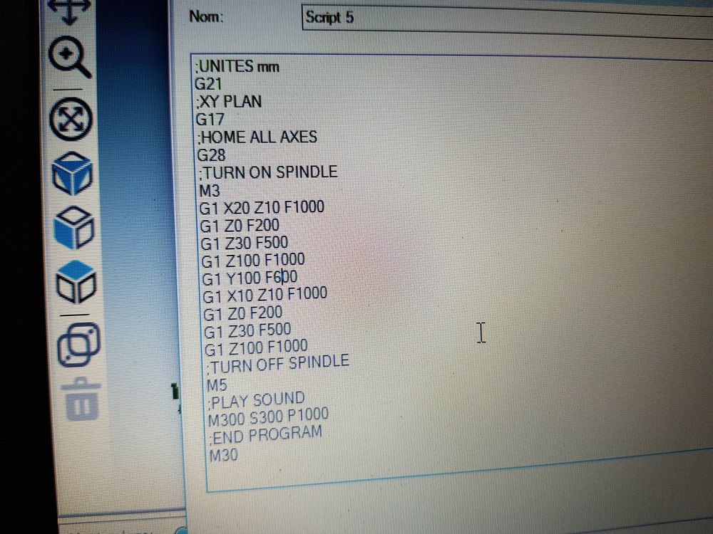
Basicaly the gcode is for drilling 2 holes, that way we can see all axes moving.
Memo about gcode : http://linuxcnc.org/docs/html/gcode.html
Final result
Here is an hero shot of the machine.
Want to see it in action ?
Also available in better quality on youtube.
Things to improve / limitations
- material Z homing
- y wheel support
- A third bearing tube near the spindle
- Change the spindle, cause not powerfull engough
- Use better tools
Files to download
– Go to project page –
Stay in touch
Hi, I'm
Joris Navarro, from Perpignan (France), a proud dad, a fab director/manager, a teacher, a ceo, a FabAcademy student, but not only. Click here to know more about me.
Check my work for FabAcademy on FabCloud GitLab
@joris.navarro.
Want to say Hi ? Please send me a message.